EP1231346A2 - Hinge joint - Google Patents
Hinge joint Download PDFInfo
- Publication number
- EP1231346A2 EP1231346A2 EP01130108A EP01130108A EP1231346A2 EP 1231346 A2 EP1231346 A2 EP 1231346A2 EP 01130108 A EP01130108 A EP 01130108A EP 01130108 A EP01130108 A EP 01130108A EP 1231346 A2 EP1231346 A2 EP 1231346A2
- Authority
- EP
- European Patent Office
- Prior art keywords
- hinge
- articulated lever
- joint according
- spring
- hinge joint
- Prior art date
- Legal status (The legal status is an assumption and is not a legal conclusion. Google has not performed a legal analysis and makes no representation as to the accuracy of the status listed.)
- Granted
Links
Images


Classifications
-
- E—FIXED CONSTRUCTIONS
- E05—LOCKS; KEYS; WINDOW OR DOOR FITTINGS; SAFES
- E05F—DEVICES FOR MOVING WINGS INTO OPEN OR CLOSED POSITION; CHECKS FOR WINGS; WING FITTINGS NOT OTHERWISE PROVIDED FOR, CONCERNED WITH THE FUNCTIONING OF THE WING
- E05F5/00—Braking devices, e.g. checks; Stops; Buffers
- E05F5/006—Braking devices, e.g. checks; Stops; Buffers for hinges having a cup-shaped fixing part, e.g. for attachment to cabinets or furniture
-
- E—FIXED CONSTRUCTIONS
- E05—LOCKS; KEYS; WINDOW OR DOOR FITTINGS; SAFES
- E05D—HINGES OR SUSPENSION DEVICES FOR DOORS, WINDOWS OR WINGS
- E05D3/00—Hinges with pins
- E05D3/06—Hinges with pins with two or more pins
- E05D3/16—Hinges with pins with two or more pins with seven parallel pins and four arms
-
- E—FIXED CONSTRUCTIONS
- E05—LOCKS; KEYS; WINDOW OR DOOR FITTINGS; SAFES
- E05F—DEVICES FOR MOVING WINGS INTO OPEN OR CLOSED POSITION; CHECKS FOR WINGS; WING FITTINGS NOT OTHERWISE PROVIDED FOR, CONCERNED WITH THE FUNCTIONING OF THE WING
- E05F1/00—Closers or openers for wings, not otherwise provided for in this subclass
- E05F1/08—Closers or openers for wings, not otherwise provided for in this subclass spring-actuated, e.g. for horizontally sliding wings
- E05F1/10—Closers or openers for wings, not otherwise provided for in this subclass spring-actuated, e.g. for horizontally sliding wings for swinging wings, e.g. counterbalance
- E05F1/12—Mechanisms in the shape of hinges or pivots, operated by springs
- E05F1/1246—Mechanisms in the shape of hinges or pivots, operated by springs with a coil spring perpendicular to the pivot axis
- E05F1/1253—Mechanisms in the shape of hinges or pivots, operated by springs with a coil spring perpendicular to the pivot axis with a compression spring
-
- E—FIXED CONSTRUCTIONS
- E05—LOCKS; KEYS; WINDOW OR DOOR FITTINGS; SAFES
- E05D—HINGES OR SUSPENSION DEVICES FOR DOORS, WINDOWS OR WINGS
- E05D3/00—Hinges with pins
- E05D3/06—Hinges with pins with two or more pins
- E05D3/16—Hinges with pins with two or more pins with seven parallel pins and four arms
- E05D2003/166—Vertical pivot-axis
-
- E—FIXED CONSTRUCTIONS
- E05—LOCKS; KEYS; WINDOW OR DOOR FITTINGS; SAFES
- E05F—DEVICES FOR MOVING WINGS INTO OPEN OR CLOSED POSITION; CHECKS FOR WINGS; WING FITTINGS NOT OTHERWISE PROVIDED FOR, CONCERNED WITH THE FUNCTIONING OF THE WING
- E05F5/00—Braking devices, e.g. checks; Stops; Buffers
- E05F5/06—Buffers or stops limiting opening of swinging wings, e.g. floor or wall stops
- E05F5/08—Buffers or stops limiting opening of swinging wings, e.g. floor or wall stops with springs
-
- E—FIXED CONSTRUCTIONS
- E05—LOCKS; KEYS; WINDOW OR DOOR FITTINGS; SAFES
- E05Y—INDEXING SCHEME RELATING TO HINGES OR OTHER SUSPENSION DEVICES FOR DOORS, WINDOWS OR WINGS AND DEVICES FOR MOVING WINGS INTO OPEN OR CLOSED POSITION, CHECKS FOR WINGS AND WING FITTINGS NOT OTHERWISE PROVIDED FOR, CONCERNED WITH THE FUNCTIONING OF THE WING
- E05Y2201/00—Constructional elements; Accessories therefore
- E05Y2201/20—Brakes; Disengaging means, e.g. clutches; Holders, e.g. locks; Stops; Accessories therefore
- E05Y2201/21—Brakes
- E05Y2201/212—Buffers
-
- E—FIXED CONSTRUCTIONS
- E05—LOCKS; KEYS; WINDOW OR DOOR FITTINGS; SAFES
- E05Y—INDEXING SCHEME RELATING TO HINGES OR OTHER SUSPENSION DEVICES FOR DOORS, WINDOWS OR WINGS AND DEVICES FOR MOVING WINGS INTO OPEN OR CLOSED POSITION, CHECKS FOR WINGS AND WING FITTINGS NOT OTHERWISE PROVIDED FOR, CONCERNED WITH THE FUNCTIONING OF THE WING
- E05Y2201/00—Constructional elements; Accessories therefore
- E05Y2201/20—Brakes; Disengaging means, e.g. clutches; Holders, e.g. locks; Stops; Accessories therefore
- E05Y2201/262—Brakes; Disengaging means, e.g. clutches; Holders, e.g. locks; Stops; Accessories therefore characterised by type of motion
- E05Y2201/264—Brakes; Disengaging means, e.g. clutches; Holders, e.g. locks; Stops; Accessories therefore characterised by type of motion linear
-
- E—FIXED CONSTRUCTIONS
- E05—LOCKS; KEYS; WINDOW OR DOOR FITTINGS; SAFES
- E05Y—INDEXING SCHEME RELATING TO HINGES OR OTHER SUSPENSION DEVICES FOR DOORS, WINDOWS OR WINGS AND DEVICES FOR MOVING WINGS INTO OPEN OR CLOSED POSITION, CHECKS FOR WINGS AND WING FITTINGS NOT OTHERWISE PROVIDED FOR, CONCERNED WITH THE FUNCTIONING OF THE WING
- E05Y2201/00—Constructional elements; Accessories therefore
- E05Y2201/20—Brakes; Disengaging means, e.g. clutches; Holders, e.g. locks; Stops; Accessories therefore
- E05Y2201/262—Brakes; Disengaging means, e.g. clutches; Holders, e.g. locks; Stops; Accessories therefore characterised by type of motion
- E05Y2201/266—Brakes; Disengaging means, e.g. clutches; Holders, e.g. locks; Stops; Accessories therefore characterised by type of motion rotary
-
- E—FIXED CONSTRUCTIONS
- E05—LOCKS; KEYS; WINDOW OR DOOR FITTINGS; SAFES
- E05Y—INDEXING SCHEME RELATING TO HINGES OR OTHER SUSPENSION DEVICES FOR DOORS, WINDOWS OR WINGS AND DEVICES FOR MOVING WINGS INTO OPEN OR CLOSED POSITION, CHECKS FOR WINGS AND WING FITTINGS NOT OTHERWISE PROVIDED FOR, CONCERNED WITH THE FUNCTIONING OF THE WING
- E05Y2201/00—Constructional elements; Accessories therefore
- E05Y2201/40—Motors; Magnets; Springs; Weights; Accessories therefore
- E05Y2201/47—Springs; Spring tensioners
- E05Y2201/484—Torsion springs
-
- E—FIXED CONSTRUCTIONS
- E05—LOCKS; KEYS; WINDOW OR DOOR FITTINGS; SAFES
- E05Y—INDEXING SCHEME RELATING TO HINGES OR OTHER SUSPENSION DEVICES FOR DOORS, WINDOWS OR WINGS AND DEVICES FOR MOVING WINGS INTO OPEN OR CLOSED POSITION, CHECKS FOR WINGS AND WING FITTINGS NOT OTHERWISE PROVIDED FOR, CONCERNED WITH THE FUNCTIONING OF THE WING
- E05Y2900/00—Application of doors, windows, wings or fittings thereof
- E05Y2900/20—Application of doors, windows, wings or fittings thereof for furnitures, e.g. cabinets
-
- E—FIXED CONSTRUCTIONS
- E05—LOCKS; KEYS; WINDOW OR DOOR FITTINGS; SAFES
- E05Y—INDEXING SCHEME RELATING TO HINGES OR OTHER SUSPENSION DEVICES FOR DOORS, WINDOWS OR WINGS AND DEVICES FOR MOVING WINGS INTO OPEN OR CLOSED POSITION, CHECKS FOR WINGS AND WING FITTINGS NOT OTHERWISE PROVIDED FOR, CONCERNED WITH THE FUNCTIONING OF THE WING
- E05Y2900/00—Application of doors, windows, wings or fittings thereof
- E05Y2900/30—Application of doors, windows, wings or fittings thereof for domestic appliances
- E05Y2900/31—Application of doors, windows, wings or fittings thereof for domestic appliances for refrigerators
Definitions
- the invention relates to a hinge joint for doors or flaps, preferably to link a door to a refrigerator and / or freezer, the body-more resistant Hinge part with the movable hinge part by several handlebars and / or at least one articulated lever is pivotally connected, at least of which a handlebar or an articulated lever is acted upon by a spring such that this the movable hinge part in at least in the open position Direction towards this open position.
- Hinge joints of this type are preferably used in the cases in for whom a moment pushing the door into the open position is desired.
- the spring exerts an opening moment on the door in the opening area due to which the door bump into the open position under impact can.
- Such a beating of the door in the open position is, however particularly disadvantageous in cooling units, since the doors of cooling units are usually provided with storage facilities, for example for bottles, so that this under the impact when struck in the open position Can knock against each other and break.
- the object of the invention is therefore a hinge joint of the beginning specified type to create, despite the in the open position existing opening moment a knocking of the door under impact Opening position is prevented, but at least mitigated.
- this object is achieved with a hinge joint specified type solved in that braking and / or damping means are provided, the hard hitting together of hinge parts and / or Cushion or prevent handlebars in the open position.
- the braking and / or damping means provided according to the invention raise this exerted by the spring in the opening area of the door or flap Opening moment does not open. However, they dampen the hitting of the feather accelerated door to the open position in such a way that an undesirable Extent of impact energy is consumed or slowed down.
- the pivotable hinge part be connected by two links with an articulated lever attached to the body-fixed Hinge part is articulated, the one facing the body-fixed hinge part Handlebar is connected by a third handlebar to the body-fixed hinge part and wherein a compression spring between the first and the second link is clamped between the open and closed positions Dead center passes through.
- the spring on both sides of the dead center position causes the door to open once Opening moment in the direction of the opening position and the other Experiences closing torque in the direction of the closed position.
- a Fridge hinge in which a spring also generates a closing moment however, in principle no special measures are required to achieve a To dampen the impact in the closing area because the impact when closing the Appliance door is dampened by the door seal.
- the articulated lever can and the third link is approximately parallel to each other. Can continue the first and the second link parallel at least in a central position to each other.
- the braking and / or Damping means consist of a spring that only at the end of Opening movement is tensioned by the handlebars and / or the articulated lever.
- the spring advantageously consists of at least one on the Swivel axis of the articulated lever attached leg spring, one of which Leg itself on the articulated lever and its other leg on the supporting body-fixed hinge part.
- the support on the body-fixed Hinge part can be made on a bolt connected to this.
- a device for setting the Swivel angle can be provided, at which the articulated lever begins, exciting to act on the spring.
- the setting direction can be from a on the articulated lever arranged set screw or an adjustable eccentric.
- the damping device can consist of a between the articulated lever or the third handlebar and the body-fixed Hinge part arranged piston-cylinder unit consist of one with the Impact damping medium, for example a gas or oil, is filled. Consists the damping device from a piston-cylinder unit filled with oil the piston expediently provided with a bore through which the oil from one piston chamber enters the other under throttling action.
- the Impact damping medium for example a gas or oil
- the Damping device from between the handlebars and / or the articulated lever and / or the body-fixed or pivotable hinge parts Friction and / or brake pads exist.
- a hinge can be seen that with particular advantage Linkage of a refrigerator door to a refrigerator can be used.
- the Hinge consists of a body-fixed hinge part 1, which when using the Hinge for articulating a refrigerator door with a side wall of the Cabinet housing is screwed.
- the hinge part 1 is made of sheet metal bent, the side leg-like parts of the web part 2 are bent at right angles.
- the hinge part 1 has an angular shape, wherein an extension of the web part 4 is bent at right angles and the raised leg parts 3 limited.
- the legs of a U-shaped curved lever 5 On the articulated bolt 4 riveted in aligned bores of the legs 3 between the legs 3, the legs of a U-shaped curved lever 5 stored. Between those angled from the web part of the articulated lever 5 Legs 6 are on hinge pins 7, 8 which are riveted into holes in the legs 6 are, the handlebars 9, 10 pivoted, the other ends articulated with the pivotable hinge part 11 are connected to the appliance door is screwed.
- the pivotable hinge part 11 also consists of a U-shaped sheet metal part, between which it is bent by its web part Legs 12 hinge pins 13, 14 are held in the bores of the legs 12 are riveted. On the hinge pin 13 is the other end of the handlebar 9 and on the hinge pin 14, the other end of the link 14 is pivotally mounted.
- the handlebars 9, 10 also consist of sheet metal parts bent in a U-shape.
- a hinge pin 16 on the the rolled-up eye of a handlebar 17 consisting of a flat sheet metal is stored, the other end of which also has a rolled-up eye on a hinge pin 18 is mounted, the holes in the legs 3 of the Body-fixed hinge part 1 is riveted.
- bearing parts for a compression spring 22 are pivotally mounted, the Compression spring 22 is supported on one pin of one bearing part, which is in the other Bearing part is guided.
- the hinge joint 1 is shown in its open position in which the Compression spring 22 to the movable hinge part 13 in its open position tries to swivel.
- the hinge pins 21 approach each other until after Moving away from a dead center position again so that the compression spring 22 to the pivotable hinge part 11 in its closed position to move and keep in it.
- This Leg spring 25 is supported with its one leg 26 on a bolt 27, the ends of which are riveted into holes in the legs 3 of the hinge part 1.
- the other leg 28 of the leg spring 25 is supported only in the area of Open position on an actuator 29 with which the web portion of the Articulated lever 5 is provided.
- FIG. 4 is again in a perspective view that on the Joint axis 4 held leg spring 25 can be seen, with one Leg 28 on the eccentric disk 32 provided with a stop 34 supported.
- leg spring itself is made of a continuous piece of spring wire wound. With the same effect, two could also be on the hinge axis 4 Leg springs that are supported by the leg spring 25 only by distinguish that the legs 28 connected by an arc from each other are separated.
Abstract
Description
Die Erfindung betrifft ein Scharniergelenk für Türen oder Klappen, vorzugsweise zum Anlenken einer Tür an ein Kühl- und/oder Gefriergerät, deren korpusfester Scharnierteil mit dem beweglichen Scharnierteil durch mehrere Lenker und/oder mindestens einen Gelenkhebel schwenkbar verbunden ist, von denen mindestens ein Lenker oder ein Gelenkhebel derart von einer Feder beaufschlagt ist, daß diese das bewegliche Scharnierteil mindestens im Bereich der Öffnungsstellung in Richtung auf diese Öffnungsstellung belastet.The invention relates to a hinge joint for doors or flaps, preferably to link a door to a refrigerator and / or freezer, the body-more resistant Hinge part with the movable hinge part by several handlebars and / or at least one articulated lever is pivotally connected, at least of which a handlebar or an articulated lever is acted upon by a spring such that this the movable hinge part in at least in the open position Direction towards this open position.
Scharniergelenke dieser Art werden vorzugsweise in den Fällen eingesetzt, in denen ein die Tür in die geöffnete Stellung drückendes Moment erwünscht ist. Andererseits übt die Feder auf die Tür im Öffnungsbereich ein Öffnungsmoment aus, aufgrund dessen die Tür unter Stoßwirkung in die Öffnungsstellung schlagen kann. Ein derartiges Schlagen der Tür in die Öffnungsstellung ist jedoch insbesondere bei Kühlgeräten nachteilig, da die Türen von Kühlgeräten üblicherweise mit Abstelleinrichtungen beispielsweise für Flaschen versehen sind, so daß diese unter der Stoßwirkung beim Anschlagen in die Öffnungsstellung der Tür aneinanderstoßen und zerbrechen können. Hinge joints of this type are preferably used in the cases in for whom a moment pushing the door into the open position is desired. On the other hand, the spring exerts an opening moment on the door in the opening area due to which the door bump into the open position under impact can. Such a beating of the door in the open position is, however particularly disadvantageous in cooling units, since the doors of cooling units are usually provided with storage facilities, for example for bottles, so that this under the impact when struck in the open position Can knock against each other and break.
Aufgabe der Erfindung ist es daher, ein Scharniergelenk der eingangs angegebenen Art zu schaffen, bei dem trotz des in der Öffnungsstellung vorhandenen Öffnungsmoments ein Schlagen der Tür unter Stoßwirkung in die Öffnungsstellung verhindert, zumindest jedoch abgemildert ist.The object of the invention is therefore a hinge joint of the beginning specified type to create, despite the in the open position existing opening moment a knocking of the door under impact Opening position is prevented, but at least mitigated.
Erfindungsgemäß wird diese Aufgabe bei einem Scharniergelenk der eingangs angegebenen Art dadurch gelöst, daß Brems- und/oder Dämpfungsmittel vorgesehen sind, die ein hartes Aneinanderschlagen von Scharnierteilen und/oder Lenkern in der Öffnungsstellung dämpfen oder verhindern.According to the invention, this object is achieved with a hinge joint specified type solved in that braking and / or damping means are provided, the hard hitting together of hinge parts and / or Cushion or prevent handlebars in the open position.
Die erfindungsgemäß vorgesehenen Brems- und/oder Dämpfungsmittel heben das durch die Feder im Öffnungsbereich der Tür oder Klappe ausgeübte Öffnungsmoment nicht auf. Sie dämpfen jedoch das Schlagen der von der Feder beschleunigten Tür in die Öffnungsstellung in der Weise, daß ein unerwünschtes Ausmaß an Schlagenergie aufgezehrt oder abgebremst wird.The braking and / or damping means provided according to the invention raise this exerted by the spring in the opening area of the door or flap Opening moment does not open. However, they dampen the hitting of the feather accelerated door to the open position in such a way that an undesirable Extent of impact energy is consumed or slowed down.
Bei dem erfindungsgemäßen Scharniergelenk kann das schwenkbare Scharnierteil durch zwei Lenker mit einem Gelenkhebel verbunden sein, der an das korpusfeste Scharnierteil angelenkt ist, wobei der dem korpusfesten Scharnierteil zugewandte Lenker durch einen dritten Lenker mit dem korpusfesten Scharnierteil verbunden ist und wobei zwischen dem ersten und dem zweiten Lenker eine Druckfeder eingespannt ist, die zwischen der Öffnungs- und Schließstellung eine Totpunktstellung durchläuft. Bei diesem erfindungsgemäß eingesetzten Scharnier bewirkt die Feder beidseits der Totpunktstellung, daß die Tür einmal ein Öffnungsmoment in Richtung auf die Öffnungsstellung und zum anderen ein Schließmoment in Richtung auf die Schließstellung erfährt. Bei einem Kühlschrankscharnier, bei dem eine Feder auch ein Schließmoment erzeugt, sind jedoch grundsätzlich keine besonderen Maßnahmen erforderlich, um eine Schlagwirkung im Schließbereich zu dämpfen, weil der Schlag beim Schließen der Gerätetür durch die Türdichtung gedämpft wird. In the hinge joint according to the invention, the pivotable hinge part be connected by two links with an articulated lever attached to the body-fixed Hinge part is articulated, the one facing the body-fixed hinge part Handlebar is connected by a third handlebar to the body-fixed hinge part and wherein a compression spring between the first and the second link is clamped between the open and closed positions Dead center passes through. With this hinge used according to the invention the spring on both sides of the dead center position causes the door to open once Opening moment in the direction of the opening position and the other Experiences closing torque in the direction of the closed position. At a Fridge hinge, in which a spring also generates a closing moment however, in principle no special measures are required to achieve a To dampen the impact in the closing area because the impact when closing the Appliance door is dampened by the door seal.
Bei diesem vorzugsweise eingesetzten Scharniergelenk können der Gelenkhebel und der dritte Lenker annähernd parallel zueinander verlaufen. Weiterhin können der erste und der zweite Lenker zumindest in einer Mittelstellung parallel zueinander verlaufen.With this hinge joint, which is preferably used, the articulated lever can and the third link is approximately parallel to each other. Can continue the first and the second link parallel at least in a central position to each other.
Nach einer bevorzugten Ausführungsform ist vorgesehen, daß die Brems- und/oder Dämpfungsmittel aus einer Feder bestehen, die erst am Ende der Öffnungsbewegung durch die Lenker und/oder den Gelenkhebel gespannt wird.According to a preferred embodiment it is provided that the braking and / or Damping means consist of a spring that only at the end of Opening movement is tensioned by the handlebars and / or the articulated lever.
Die Feder besteht zweckmäßigerweise aus mindestens einer auf die Schwenkachse des Gelenkhebels aufgesetzten Schenkelfeder, deren einer Schenkel sich an dem Gelenkhebel und deren anderer Schenkel sich an dem korpusfesten Scharnierteil abstützt. Die Abstützung an dem korpusfesten Scharnierteil kann auf einem mit diesem verbundenen Bolzen erfolgen.The spring advantageously consists of at least one on the Swivel axis of the articulated lever attached leg spring, one of which Leg itself on the articulated lever and its other leg on the supporting body-fixed hinge part. The support on the body-fixed Hinge part can be made on a bolt connected to this.
Um die Dämpfungswirkung der Feder in der erforderlichen oder gewünschten Weise einstellen zu können, kann eine Einrichtung zur Einstellung des Schwenkwinkels vorgesehen sein, bei dem der Gelenkhebel beginnt, spannend auf die Feder einzuwirken. Die Einstellrichtung kann aus einer an dem Gelenkhebel angeordneten Stellschraube oder einem einstellbaren Exzenter bestehen.To the damping effect of the spring in the required or desired To be able to set a device for setting the Swivel angle can be provided, at which the articulated lever begins, exciting to act on the spring. The setting direction can be from a on the articulated lever arranged set screw or an adjustable eccentric.
Nach einer anderen Ausführungsform kann die Dämpfungseinrichtung aus einer zwischen dem Gelenkhebel oder dem dritten Lenker und dem korpusfesten Scharnierteil angeordneten Kolben-Zylinder-Einheit bestehen, die mit einem den Schlag dämpfenden Medium, beispielsweise einem Gas oder Öl, gefüllt ist. Besteht die Dämpfungseinrichtung aus einer mit Öl gefüllten Kolben-Zylinder-Einheit, wird der Kolben zweckmäßigerweise mit einer Bohrung versehen, durch die das Öl von einer Kolbenkammer in die anderen unter Drosselwirkung eintritt.According to another embodiment, the damping device can consist of a between the articulated lever or the third handlebar and the body-fixed Hinge part arranged piston-cylinder unit consist of one with the Impact damping medium, for example a gas or oil, is filled. Consists the damping device from a piston-cylinder unit filled with oil the piston expediently provided with a bore through which the oil from one piston chamber enters the other under throttling action.
Nach einer weiteren Ausführungsform ist vorgesehen, daß die Dämpfungseinrichtung aus zwischen den Lenkern und/oder dem Gelenkhebel und/oder dem korpusfesten oder verschwenkbaren Scharnierteilen angeordneten Reib- und/oder Bremsbelägen bestehen.According to a further embodiment it is provided that the Damping device from between the handlebars and / or the articulated lever and / or the body-fixed or pivotable hinge parts Friction and / or brake pads exist.
Ausführungsbeispiele der Erfindung werden nachstehend anhand der Zeichnung näher erläutert. In dieser zeigt
- Fig. 1
- eine Seitenansicht eines Scharniergelenks mit einer aus einer Schenkelfeder bestehenden Dämpfungseinrichtung,
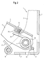
- Fig. 2
- einen vergrößerten Ausschnitt aus der Fig. 1,
- Fig. 3
- eine perspektivische Ansicht der Anordnung der Dämpfungsfeder in dem Scharniergelenk und
- Fig. 4
- eine perspektivische Ansicht der Einrichtung zum Einstellen des Schließwinkels, bei dem die Dämpfungsfeder beginnt, ihre Wirkung zu entfalten.
- Fig. 1
- 2 shows a side view of a hinge joint with a damping device consisting of a leg spring,
- Fig. 2
- 2 shows an enlarged detail from FIG. 1,
- Fig. 3
- a perspective view of the arrangement of the damping spring in the hinge joint and
- Fig. 4
- a perspective view of the device for adjusting the closing angle at which the damping spring begins to develop its effect.
Aus Fig. 1 ist ein Scharnier ersichtlich, daß sich mit besonderem Vorteil zur
Anlenkung einer Kühlschranktür an einen Kühlschrank verwenden läßt. Das
Scharnier besteht aus einem korpusfesten Scharnierteil 1, das bei Verwendung des
Scharniers zur Anlenkung einer Kühlschranktür mit einer Seitenwand des
Schrankgehäuses verschraubt wird. Das Scharnierteil 1 ist aus einem Blech
gebogen, wobei von dem Stegteil 2 die seitlichen schenkelartigen Teile 3
rechtwinkelig abgebogen sind. Das Scharnierteil 1 weist eine Winkelform auf, wobei
eine Verlängerung des Stegteils 4 rechtwinkelig abgebogen ist und die
hochgezogenen Schenkelteile 3 begrenzt.From Fig. 1 a hinge can be seen that with particular advantage
Linkage of a refrigerator door to a refrigerator can be used. The
Hinge consists of a body-fixed
Auf dem in fluchtenden Bohrungen der Schenkel 3 vernieteten Gelenkbolzen 4 sind
zwischen den Schenkeln 3 die Schenkel eines U-förmig gekrümmten Gelenkhebels
5 gelagert. Zwischen den von dem Stegteil des Gelenkhebels 5 abgewinkelten
Schenkeln 6 sind auf Gelenkbolzen 7, 8, die in Bohrungen der Schenkel 6 vernietet
sind, die Lenker 9, 10 schwenkbar gelagert, deren anderen Enden gelenkig mit
dem verschwenkbaren Scharnierteil 11 verbunden sind, das mit der Gerätetür
verschraubt ist. Das verschwenkbare Scharnierteil 11 besteht ebenfalls aus einem
U-förmig gebogenen Blechteil, zwischen dessen von dessen Stegteil abgebogenen
Schenkeln 12 Gelenkbolzen 13, 14 gehaltert sind, die in Bohrungen der Schenkel
12 vernietet sind. Auf dem Gelenkbolzen 13 ist das andere Ende des Lenkers 9 und
auf dem Gelenkbolzen 14 das andere Ende des Lenkers 14 schwenkbar gelagert.
Auch die Lenker 9, 10 bestehen aus U-förmig gebogenen Blechteilen. An dem
Lenker 9 ist zwischen dessen Schenkeln ein Gelenkbolzen 16 gehaltert, auf dem
das eingerollte Auge eines aus einem flachen Blech bestehenden Lenkers 17
gelagert ist, dessen anderes Ende ebenfalls ein eingerolltes Auge aufweist, das auf
einem Gelenkbolzen 18 gelagert ist, der in Bohrungen der Schenkel 3 des
korpusfesten Scharnierteils 1 vernietet ist.On the articulated
Auf dem Gelenkbolzen 20, der zwischen den Schenkeln des Lenkers 10 gehaltert
ist, und dem Gelenkbolzen 21, der zwischen den Schenkeln des Lenkers 9
gehaltert ist, sind Lagerteile für eine Druckfeder 22 schwenkbar gelagert, wobei die
Druckfeder 22 auf einem Stift eines Lagerteils gehaltert ist, der in dem anderen
Lagerteil verschieblich geführt ist.On the
Das Scharniergelenk 1 ist in seiner Öffnungsstellung dargestellt, in der die
Druckfeder 22 das bewegliche Scharnierteil 13 in seine geöffnete Stellung zu
verschwenken trachtet. Beim Verschwenken des verschwenkbaren Scharnierteils
11 in die Schließstellung nähern sich die Gelenkbolzen 21 einander an, bis sie nach
Durchwanderung einer Totpunktstellung sich wieder voneinander entfernen, so daß
die Druckfeder 22 das verschwenkbare Scharnierteil 11 in seine Schließstellung zu
bewegen trachtet und in dieser hält.The
Um nach dem Durchwandern der Totpunktstellung ein unerwünschtes Schlagen
der Tür in die Öffnungsstellung zu vermeiden, ist auf den Gelenkbolzen 4 zwischen
den Schenkeln 6 des Gelenkhebels 5 eine Schenkelfeder gehaltert. Diese
Schenkelfeder 25 stützt sich mit ihrem einen Schenkel 26 auf einem Bolzen 27 ab,
dessen Enden in Bohrungen der Schenkel 3 des Scharnierteils 1 vernietet sind. Der
andere Schenkel 28 der Schenkelfeder 25 stützt sich erst im Bereich der
Öffnungsstellung auf eine Stelleinrichtung 29 ab, mit der der Stegteil des
Gelenkhebels 5 versehen ist.To an undesirable hitting after walking through the dead center position
to avoid the door in the open position is on the
Wie aus Fig. 2 ersichtlich ist, besteht die Abstützeinrichtung 29 für den Schenkel 28
der Schenkelfeder 25 aus einer Stellschraube 30, die in eine mit einer Bördelung
versehene Gewindebohrung des Stegteils des Gelenkhebels 5 eingeschraubt ist.As can be seen from FIG. 2, there is the
Bei der Ausführungsform nach Fig. 3 ist in einer Bohrung des Stegteils des
Gelenkhebels 5 eine exzentrische Scheibe 32 gehaltert, die mit einer
Sechskantöffnung versehen ist, so daß sie sich durch einen Inbus-Schlüssel
verdrehen läßt. Durch entsprechende Verdrehung der Exzenterscheibe 32 läßt sich
der Winkel einstellen, unter dem im Öffnungsbereich die Schenkelfeder 25 zur
Wirkung kommt.3 is in a bore of the web part of the
Aus Fig. 4 ist nochmals in einer perspektivischen Darstellung die auf der
Gelenkachse 4 gehalterte Schenkelfeder 25 ersichtlich, die sich mit ihrem einen
Schenkel 28 auf der mit einem Anschlag 34 versehenen exzentrischen Scheibe 32
abstützt.From Fig. 4 is again in a perspective view that on the
Die Schenkelfeder selbst ist aus einem durchgehenden Federdrahtstück
gewunden. Mit gleicher Wirkung könnten auf die Gelenkachse 4 auch zwei
Schenkelfedern gehaltert sein, die sich von der Schenkelfeder 25 nur dadurch
unterscheiden, daß die durch einen Bogen verbundenen Schenkel 28 voneinander
getrennt sind.The leg spring itself is made of a continuous piece of spring wire
wound. With the same effect, two could also be on the
Claims (11)
dadurch gekennzeichnet, daß Brems- und/oder Dämpfungsmittel vorgesehen sind, die ein hartes Aneinanderschlagen von Scharnierteilen und/oder Lenkern in der Öffnungsstellung dämpfen oder verhindern. Hinge joint for doors or flaps, preferably for articulating a door to a refrigerator and / or freezer, the body-fixed hinge part (1) of which is pivotally connected to the movable hinge part (11) by a plurality of links and / or an articulated lever, of which at least one link or an articulated lever is acted upon by a spring in such a way that it loads the movable hinge part (11) at least in the region of the open position in the direction of this open position,
characterized in that braking and / or damping means are provided which dampen or prevent hard hitting of hinge parts and / or handlebars in the open position.
daß der dem korpusfesten Scharnierteil (1) zugewandte Lenker (9) durch einen dritten Lenker (17) mit dem korpusfesten Scharnierteil (1) verbunden ist und
daß zwischen dem ersten und dem zweiten Lenker (9, 10) eine Druckfeder (22) eingespannt ist, die zwischen der Öffnungs- und Schließstellung eine Totpunktstellung durchläuft.Hinge joint according to claim 1, characterized in that the pivotable hinge part (11) is connected by two links (9, 10) to an articulated lever (5) which is articulated to the hinge part (1) fixed to the body,
that the handlebar part (1) facing the body-fixed hinge part (1) is connected by a third link (17) to the body-fixed hinge part (1) and
that between the first and the second link (9, 10) a compression spring (22) is clamped, which passes through a dead center position between the open and closed positions.
Applications Claiming Priority (4)
| Application Number | Priority Date | Filing Date | Title |
|---|---|---|---|
| DE20102454 | 2001-02-13 | ||
| DE20102454U | 2001-02-13 | ||
| DE20102998U | 2001-02-20 | ||
| DE20102998U DE20102998U1 (en) | 2001-02-13 | 2001-02-20 | Hinge joint |
Publications (3)
| Publication Number | Publication Date |
|---|---|
| EP1231346A2 true EP1231346A2 (en) | 2002-08-14 |
| EP1231346A3 EP1231346A3 (en) | 2009-08-12 |
| EP1231346B1 EP1231346B1 (en) | 2012-02-01 |
Family
ID=26056814
Family Applications (1)
| Application Number | Title | Priority Date | Filing Date |
|---|---|---|---|
| EP20010130108 Expired - Lifetime EP1231346B1 (en) | 2001-02-13 | 2001-12-18 | Hinge joint |
Country Status (1)
| Country | Link |
|---|---|
| EP (1) | EP1231346B1 (en) |
Cited By (11)
| Publication number | Priority date | Publication date | Assignee | Title |
|---|---|---|---|---|
| EP1736627A2 (en) | 2005-06-21 | 2006-12-27 | Daniele Zetti | Sprung hinge for supporting a closure element |
| WO2007042094A1 (en) * | 2005-10-13 | 2007-04-19 | Hetal-Werke Franz Hettich Gmbh & Co. Kg | Fitting for fastening a front shutter (or door) in a pivotable manner on a furniture cabinet |
| DE202008013991U1 (en) | 2008-10-20 | 2010-04-01 | Liebherr-Hausgeräte Ochsenhausen GmbH | Fridge and / or freezer |
| WO2011113740A1 (en) * | 2010-03-17 | 2011-09-22 | Hettich-Oni Gmbh & Co. Kg | Hinge |
| EP2527576A1 (en) * | 2009-04-28 | 2012-11-28 | Hawa Ag | Moving device for pivotable partition elements and furniture |
| CN102874673A (en) * | 2012-09-13 | 2013-01-16 | 湖北江汉建筑工程机械有限公司 | Flipping gate buffering device for construction hoist cage |
| EP2063055A3 (en) * | 2007-11-22 | 2013-05-15 | Spreafico Cerniere S.r.L. | Snap hinge for furniture |
| EP1815096B1 (en) * | 2004-11-22 | 2014-01-08 | Julius Blum GmbH | Hinge provided with damping device |
| CN107965223A (en) * | 2017-12-20 | 2018-04-27 | 广东星鹏实业有限公司 | A kind of buffer hinge device |
| CN107989497A (en) * | 2017-11-10 | 2018-05-04 | 广东东泰五金精密制造有限公司 | A kind of big lid position hinge for furniture |
| CN108332498A (en) * | 2018-04-09 | 2018-07-27 | 江苏星徽精密科技有限公司 | A kind of built-in refrigerator buffer hinge |
Families Citing this family (1)
| Publication number | Priority date | Publication date | Assignee | Title |
|---|---|---|---|---|
| CN106545253B (en) * | 2016-12-06 | 2018-05-25 | 昆山湖华金属制品有限公司 | Linkage and furniture |
Citations (3)
| Publication number | Priority date | Publication date | Assignee | Title |
|---|---|---|---|---|
| DE2708545A1 (en) | 1977-02-28 | 1978-08-31 | Lautenschlaeger Kg Karl | FOUR-JOINT FURNITURE HINGE |
| DE2751491A1 (en) | 1977-11-18 | 1979-05-23 | Hettich Paul & Co | Furniture hinge assembly - has leg spring bearing against pivot pins jointed by links of hinge leaves |
| DE3239989A1 (en) | 1982-10-28 | 1984-05-03 | Hetal-Werke Franz Hettich Gmbh & Co, 7297 Alpirsbach | Fitting for the pivotable fastening of a front flap to a cupboard |
Family Cites Families (2)
| Publication number | Priority date | Publication date | Assignee | Title |
|---|---|---|---|---|
| US2629892A (en) * | 1949-01-05 | 1953-03-03 | George W Slopa | Yieldable overlap hinge |
| IT1269279B (en) * | 1994-12-16 | 1997-03-26 | Tgn Spa | CLOSED HINGE FOR FURNITURE |
-
2001
- 2001-12-18 EP EP20010130108 patent/EP1231346B1/en not_active Expired - Lifetime
Patent Citations (3)
| Publication number | Priority date | Publication date | Assignee | Title |
|---|---|---|---|---|
| DE2708545A1 (en) | 1977-02-28 | 1978-08-31 | Lautenschlaeger Kg Karl | FOUR-JOINT FURNITURE HINGE |
| DE2751491A1 (en) | 1977-11-18 | 1979-05-23 | Hettich Paul & Co | Furniture hinge assembly - has leg spring bearing against pivot pins jointed by links of hinge leaves |
| DE3239989A1 (en) | 1982-10-28 | 1984-05-03 | Hetal-Werke Franz Hettich Gmbh & Co, 7297 Alpirsbach | Fitting for the pivotable fastening of a front flap to a cupboard |
Cited By (21)
| Publication number | Priority date | Publication date | Assignee | Title |
|---|---|---|---|---|
| EP1815096B1 (en) * | 2004-11-22 | 2014-01-08 | Julius Blum GmbH | Hinge provided with damping device |
| EP1736627A3 (en) * | 2005-06-21 | 2008-01-23 | Daniele Zetti | Sprung hinge for supporting a closure element |
| US7591046B2 (en) | 2005-06-21 | 2009-09-22 | Daniele Zetti | Sprung hinge for supporting a closure element |
| EP1736627A2 (en) | 2005-06-21 | 2006-12-27 | Daniele Zetti | Sprung hinge for supporting a closure element |
| WO2007042094A1 (en) * | 2005-10-13 | 2007-04-19 | Hetal-Werke Franz Hettich Gmbh & Co. Kg | Fitting for fastening a front shutter (or door) in a pivotable manner on a furniture cabinet |
| EP2063055A3 (en) * | 2007-11-22 | 2013-05-15 | Spreafico Cerniere S.r.L. | Snap hinge for furniture |
| DE102009049984A1 (en) | 2008-10-20 | 2010-04-22 | Liebherr-Hausgeräte Ochsenhausen GmbH | Cooling or refrigerating device has door that is pivoted by two multi-joint hinges, and space, which is provided in range of twenty six millimeter to forty six millimeter |
| DE202008013991U1 (en) | 2008-10-20 | 2010-04-01 | Liebherr-Hausgeräte Ochsenhausen GmbH | Fridge and / or freezer |
| EP2527576A1 (en) * | 2009-04-28 | 2012-11-28 | Hawa Ag | Moving device for pivotable partition elements and furniture |
| AT514903A5 (en) * | 2010-03-17 | 2015-04-15 | Hettich Oni Gmbh & Co Kg | hinge |
| WO2011113740A1 (en) * | 2010-03-17 | 2011-09-22 | Hettich-Oni Gmbh & Co. Kg | Hinge |
| CN102844514A (en) * | 2010-03-17 | 2012-12-26 | 黑蒂赫-欧尼有限公司及两合公司 | Hinge |
| CN102844514B (en) * | 2010-03-17 | 2015-05-27 | 黑蒂赫-欧尼有限公司及两合公司 | Hinge |
| AT514903B1 (en) * | 2010-03-17 | 2015-06-15 | Hettich Oni Gmbh & Co Kg | hinge |
| CN102874673A (en) * | 2012-09-13 | 2013-01-16 | 湖北江汉建筑工程机械有限公司 | Flipping gate buffering device for construction hoist cage |
| CN102874673B (en) * | 2012-09-13 | 2014-02-26 | 湖北江汉建筑工程机械有限公司 | Flipping gate buffering device for construction hoist cage |
| CN107989497A (en) * | 2017-11-10 | 2018-05-04 | 广东东泰五金精密制造有限公司 | A kind of big lid position hinge for furniture |
| CN107965223A (en) * | 2017-12-20 | 2018-04-27 | 广东星鹏实业有限公司 | A kind of buffer hinge device |
| CN107965223B (en) * | 2017-12-20 | 2023-06-23 | 广东星鹏实业有限公司 | Buffer hinge device |
| CN108332498A (en) * | 2018-04-09 | 2018-07-27 | 江苏星徽精密科技有限公司 | A kind of built-in refrigerator buffer hinge |
| CN108332498B (en) * | 2018-04-09 | 2023-09-08 | 江苏玖星精密科技集团有限公司 | Buffer hinge of embedded refrigerator |
Also Published As
| Publication number | Publication date |
|---|---|
| EP1231346B1 (en) | 2012-02-01 |
| EP1231346A3 (en) | 2009-08-12 |
Similar Documents
| Publication | Publication Date | Title |
|---|---|---|
| EP2126492B1 (en) | Refrigerator and/or freezer | |
| EP2140091B1 (en) | Double-link hinge | |
| EP2268882B1 (en) | Furniture hinge | |
| EP1818491B1 (en) | Fitting for a cabinet lid | |
| EP1231346A2 (en) | Hinge joint | |
| EP1398446B1 (en) | Openable flap, in particular exhaust gas flap | |
| EP0794309A1 (en) | Hold fitting for a shutter linked to the ceiling wall of a cabinet by means of a horizontal axis | |
| DE102006019332A1 (en) | Hinge device for refrigerator housing has first part and second part which pivotally swings by means of a hinge whereby a piston-cylinder damping unit is actively arranged between said first part and second part | |
| DE102006059247A1 (en) | Furniture hinge with a damping device | |
| DE3605637C2 (en) | ||
| DE20306043U1 (en) | A refrigerator or freezer cabinet door has an automatically closing hinge system and a damping unit coming into operation just before closure | |
| EP2069600B1 (en) | Furniture hinge having a damping device | |
| DE102006036473A1 (en) | Hinge arrangement | |
| DE10203269B4 (en) | Fitting device for a furniture flap | |
| DE3026630C2 (en) | Hinge with braking device for hinged flaps or the like about horizontal axes. | |
| WO2018024379A1 (en) | Damper device | |
| DE4236444C2 (en) | Hinge, preferably furniture hinge | |
| WO2005108726A1 (en) | Hinge, especially for furniture parts | |
| DE20102998U1 (en) | Hinge joint | |
| DE2656052C2 (en) | Disc brakes, in particular for rail vehicles | |
| EP0670406B1 (en) | Device for limitation of opening of doorwings | |
| EP3722546A1 (en) | Hinge for a device, in particular for a kitchen and/or domestic device, and a device, in particular kitchen and/or domestic device | |
| DE202005002609U1 (en) | Damper arrangement for closing movement of movable furniture parts has housing with long narrow, shallow body in complementary shaped aperture in one furniture part and at least partly open towards other part in pressure part region | |
| DE102020206544B4 (en) | Linkage for a door closer or door operator, door closer or door operator and door | |
| DE202006004873U1 (en) | Hinge for a swing flap/door at furniture, with a joint mechanism, has clamping pads with a radial sliding movement at the two mounting sections to be extended into recesses on installation |
Legal Events
| Date | Code | Title | Description |
|---|---|---|---|
| PUAI | Public reference made under article 153(3) epc to a published international application that has entered the european phase |
Free format text: ORIGINAL CODE: 0009012 |
|
| 17P | Request for examination filed |
Effective date: 20020307 |
|
| AK | Designated contracting states |
Kind code of ref document: A2 Designated state(s): AT BE CH CY DE DK ES FI FR GB GR IE IT LI LU MC NL PT SE TR |
|
| AX | Request for extension of the european patent |
Free format text: AL;LT;LV;MK;RO;SI |
|
| PUAL | Search report despatched |
Free format text: ORIGINAL CODE: 0009013 |
|
| AK | Designated contracting states |
Kind code of ref document: A3 Designated state(s): AT BE CH CY DE DK ES FI FR GB GR IE IT LI LU MC NL PT SE TR |
|
| AX | Request for extension of the european patent |
Extension state: AL LT LV MK RO SI |
|
| 17Q | First examination report despatched |
Effective date: 20100125 |
|
| AKX | Designation fees paid |
Designated state(s): AT BE CH CY DE DK ES FI FR GB GR IE IT LI LU MC NL PT SE TR |
|
| REG | Reference to a national code |
Ref country code: DE Ref legal event code: R079 Ref document number: 50116047 Country of ref document: DE Free format text: PREVIOUS MAIN CLASS: E05D0003060000 Ipc: E05F0005000000 |
|
| GRAP | Despatch of communication of intention to grant a patent |
Free format text: ORIGINAL CODE: EPIDOSNIGR1 |
|
| RIC1 | Information provided on ipc code assigned before grant |
Ipc: E05F 5/00 20060101AFI20110907BHEP Ipc: E05F 1/12 20060101ALI20110907BHEP Ipc: E05D 3/16 20060101ALI20110907BHEP |
|
| GRAS | Grant fee paid |
Free format text: ORIGINAL CODE: EPIDOSNIGR3 |
|
| RAP1 | Party data changed (applicant data changed or rights of an application transferred) |
Owner name: LIEBHERR-HAUSGERAETE OCHSENHAUSEN GMBH |
|
| GRAA | (expected) grant |
Free format text: ORIGINAL CODE: 0009210 |
|
| AK | Designated contracting states |
Kind code of ref document: B1 Designated state(s): AT BE CH CY DE DK ES FI FR GB GR IE IT LI LU MC NL PT SE TR |
|
| REG | Reference to a national code |
Ref country code: GB Ref legal event code: FG4D Free format text: NOT ENGLISH |
|
| REG | Reference to a national code |
Ref country code: AT Ref legal event code: REF Ref document number: 543977 Country of ref document: AT Kind code of ref document: T Effective date: 20120215 Ref country code: CH Ref legal event code: EP |
|
| REG | Reference to a national code |
Ref country code: ES Ref legal event code: FG2A Ref document number: 2377515 Country of ref document: ES Kind code of ref document: T3 Effective date: 20120328 |
|
| REG | Reference to a national code |
Ref country code: DE Ref legal event code: R096 Ref document number: 50116047 Country of ref document: DE Effective date: 20120329 |
|
| REG | Reference to a national code |
Ref country code: NL Ref legal event code: VDEP Effective date: 20120201 |
|
| PG25 | Lapsed in a contracting state [announced via postgrant information from national office to epo] |
Ref country code: NL Free format text: LAPSE BECAUSE OF FAILURE TO SUBMIT A TRANSLATION OF THE DESCRIPTION OR TO PAY THE FEE WITHIN THE PRESCRIBED TIME-LIMIT Effective date: 20120201 |
|
| REG | Reference to a national code |
Ref country code: IE Ref legal event code: FD4D |
|
| PG25 | Lapsed in a contracting state [announced via postgrant information from national office to epo] |
Ref country code: FI Free format text: LAPSE BECAUSE OF FAILURE TO SUBMIT A TRANSLATION OF THE DESCRIPTION OR TO PAY THE FEE WITHIN THE PRESCRIBED TIME-LIMIT Effective date: 20120201 Ref country code: PT Free format text: LAPSE BECAUSE OF FAILURE TO SUBMIT A TRANSLATION OF THE DESCRIPTION OR TO PAY THE FEE WITHIN THE PRESCRIBED TIME-LIMIT Effective date: 20120601 Ref country code: GR Free format text: LAPSE BECAUSE OF FAILURE TO SUBMIT A TRANSLATION OF THE DESCRIPTION OR TO PAY THE FEE WITHIN THE PRESCRIBED TIME-LIMIT Effective date: 20120502 |
|
| PG25 | Lapsed in a contracting state [announced via postgrant information from national office to epo] |
Ref country code: CY Free format text: LAPSE BECAUSE OF FAILURE TO SUBMIT A TRANSLATION OF THE DESCRIPTION OR TO PAY THE FEE WITHIN THE PRESCRIBED TIME-LIMIT Effective date: 20120201 |
|
| PG25 | Lapsed in a contracting state [announced via postgrant information from national office to epo] |
Ref country code: DK Free format text: LAPSE BECAUSE OF FAILURE TO SUBMIT A TRANSLATION OF THE DESCRIPTION OR TO PAY THE FEE WITHIN THE PRESCRIBED TIME-LIMIT Effective date: 20120201 Ref country code: SE Free format text: LAPSE BECAUSE OF FAILURE TO SUBMIT A TRANSLATION OF THE DESCRIPTION OR TO PAY THE FEE WITHIN THE PRESCRIBED TIME-LIMIT Effective date: 20120201 Ref country code: IE Free format text: LAPSE BECAUSE OF FAILURE TO SUBMIT A TRANSLATION OF THE DESCRIPTION OR TO PAY THE FEE WITHIN THE PRESCRIBED TIME-LIMIT Effective date: 20120201 |
|
| PLBE | No opposition filed within time limit |
Free format text: ORIGINAL CODE: 0009261 |
|
| STAA | Information on the status of an ep patent application or granted ep patent |
Free format text: STATUS: NO OPPOSITION FILED WITHIN TIME LIMIT |
|
| 26N | No opposition filed |
Effective date: 20121105 |
|
| REG | Reference to a national code |
Ref country code: DE Ref legal event code: R097 Ref document number: 50116047 Country of ref document: DE Effective date: 20121105 |
|
| BERE | Be: lapsed |
Owner name: LIEBHERR-HAUSGERATE OCHSENHAUSEN G.M.B.H. Effective date: 20121231 |
|
| PG25 | Lapsed in a contracting state [announced via postgrant information from national office to epo] |
Ref country code: MC Free format text: LAPSE BECAUSE OF NON-PAYMENT OF DUE FEES Effective date: 20121231 |
|
| REG | Reference to a national code |
Ref country code: CH Ref legal event code: PL |
|
| GBPC | Gb: european patent ceased through non-payment of renewal fee |
Effective date: 20121218 |
|
| PG25 | Lapsed in a contracting state [announced via postgrant information from national office to epo] |
Ref country code: BE Free format text: LAPSE BECAUSE OF NON-PAYMENT OF DUE FEES Effective date: 20121231 |
|
| PG25 | Lapsed in a contracting state [announced via postgrant information from national office to epo] |
Ref country code: CH Free format text: LAPSE BECAUSE OF NON-PAYMENT OF DUE FEES Effective date: 20121231 Ref country code: LI Free format text: LAPSE BECAUSE OF NON-PAYMENT OF DUE FEES Effective date: 20121231 |
|
| PG25 | Lapsed in a contracting state [announced via postgrant information from national office to epo] |
Ref country code: GB Free format text: LAPSE BECAUSE OF NON-PAYMENT OF DUE FEES Effective date: 20121218 |
|
| REG | Reference to a national code |
Ref country code: AT Ref legal event code: MM01 Ref document number: 543977 Country of ref document: AT Kind code of ref document: T Effective date: 20121218 |
|
| PG25 | Lapsed in a contracting state [announced via postgrant information from national office to epo] |
Ref country code: TR Free format text: LAPSE BECAUSE OF FAILURE TO SUBMIT A TRANSLATION OF THE DESCRIPTION OR TO PAY THE FEE WITHIN THE PRESCRIBED TIME-LIMIT Effective date: 20120201 |
|
| PG25 | Lapsed in a contracting state [announced via postgrant information from national office to epo] |
Ref country code: AT Free format text: LAPSE BECAUSE OF NON-PAYMENT OF DUE FEES Effective date: 20121218 Ref country code: LU Free format text: LAPSE BECAUSE OF NON-PAYMENT OF DUE FEES Effective date: 20121218 |
|
| REG | Reference to a national code |
Ref country code: FR Ref legal event code: PLFP Year of fee payment: 15 |
|
| REG | Reference to a national code |
Ref country code: FR Ref legal event code: PLFP Year of fee payment: 16 |
|
| REG | Reference to a national code |
Ref country code: FR Ref legal event code: PLFP Year of fee payment: 17 |
|
| PGFP | Annual fee paid to national office [announced via postgrant information from national office to epo] |
Ref country code: FR Payment date: 20181221 Year of fee payment: 18 |
|
| PGFP | Annual fee paid to national office [announced via postgrant information from national office to epo] |
Ref country code: IT Payment date: 20190124 Year of fee payment: 17 Ref country code: ES Payment date: 20190115 Year of fee payment: 18 |
|
| PGFP | Annual fee paid to national office [announced via postgrant information from national office to epo] |
Ref country code: DE Payment date: 20200102 Year of fee payment: 19 |
|
| PG25 | Lapsed in a contracting state [announced via postgrant information from national office to epo] |
Ref country code: IT Free format text: LAPSE BECAUSE OF NON-PAYMENT OF DUE FEES Effective date: 20191218 Ref country code: FR Free format text: LAPSE BECAUSE OF NON-PAYMENT OF DUE FEES Effective date: 20191231 |
|
| REG | Reference to a national code |
Ref country code: ES Ref legal event code: FD2A Effective date: 20210525 |
|
| REG | Reference to a national code |
Ref country code: DE Ref legal event code: R119 Ref document number: 50116047 Country of ref document: DE |
|
| PG25 | Lapsed in a contracting state [announced via postgrant information from national office to epo] |
Ref country code: ES Free format text: LAPSE BECAUSE OF NON-PAYMENT OF DUE FEES Effective date: 20191219 |
|
| PG25 | Lapsed in a contracting state [announced via postgrant information from national office to epo] |
Ref country code: DE Free format text: LAPSE BECAUSE OF NON-PAYMENT OF DUE FEES Effective date: 20210701 |