EP1231327A1 - Fräswerkzeug zum Schneiden von hartem Boden und von klebrigem Boden - Google Patents
Fräswerkzeug zum Schneiden von hartem Boden und von klebrigem Boden Download PDFInfo
- Publication number
- EP1231327A1 EP1231327A1 EP02290094A EP02290094A EP1231327A1 EP 1231327 A1 EP1231327 A1 EP 1231327A1 EP 02290094 A EP02290094 A EP 02290094A EP 02290094 A EP02290094 A EP 02290094A EP 1231327 A1 EP1231327 A1 EP 1231327A1
- Authority
- EP
- European Patent Office
- Prior art keywords
- rim
- milling
- motor
- milling tool
- tool according
- Prior art date
- Legal status (The legal status is an assumption and is not a legal conclusion. Google has not performed a legal analysis and makes no representation as to the accuracy of the status listed.)
- Granted
Links
Images


Classifications
-
- E—FIXED CONSTRUCTIONS
- E02—HYDRAULIC ENGINEERING; FOUNDATIONS; SOIL SHIFTING
- E02F—DREDGING; SOIL-SHIFTING
- E02F3/00—Dredgers; Soil-shifting machines
- E02F3/04—Dredgers; Soil-shifting machines mechanically-driven
- E02F3/18—Dredgers; Soil-shifting machines mechanically-driven with digging wheels turning round an axis, e.g. bucket-type wheels
- E02F3/22—Component parts
-
- E—FIXED CONSTRUCTIONS
- E02—HYDRAULIC ENGINEERING; FOUNDATIONS; SOIL SHIFTING
- E02F—DREDGING; SOIL-SHIFTING
- E02F3/00—Dredgers; Soil-shifting machines
- E02F3/04—Dredgers; Soil-shifting machines mechanically-driven
- E02F3/18—Dredgers; Soil-shifting machines mechanically-driven with digging wheels turning round an axis, e.g. bucket-type wheels
- E02F3/20—Dredgers; Soil-shifting machines mechanically-driven with digging wheels turning round an axis, e.g. bucket-type wheels with tools that only loosen the material, i.e. mill-type wheels
- E02F3/205—Dredgers; Soil-shifting machines mechanically-driven with digging wheels turning round an axis, e.g. bucket-type wheels with tools that only loosen the material, i.e. mill-type wheels with a pair of digging wheels, e.g. slotting machines
Definitions
- the present invention relates to a milling tool for the cutting hard and sticky terrains.
- milling cutters For the creation of trenches in the ground in the form of walls, we know of milling tools most often called milling cutters. They comprise a body suspended at the end of lifting means, this body being provided at its lower end with two wheels driven by hydraulic motors with teeth distributed over two drums with horizontal axes. These teeth have the role of destructuring or cutting the ground to bring it back to small pieces that can be conveyed by suction using a pipe including the cutter is equipped and which is connected to a suction pump.
- Such a milling or excavation tool is described in particular in European patent 262,050 in the name of the plaintiff.
- the strawberry has two wheels that rotate in opposite directions, each wheel comprising two drums.
- the wheels are put in rotation by a hydraulic motor or by two hydraulic motors positioned in the central hub of each wheel and arranged at the lower end of the tool body.
- the drums are usually constituted by a ferrule which is mechanically connected to the part the engine.
- the teeth are welded to this ferrule.
- the tooth is often enhanced by welding the active part on a sheet which has the role increase its height.
- the arrangement of the teeth strawberries may vary.
- FIGs 1A and 1B attached there is shown so simplified a first embodiment of the known milling tool.
- the lower part 10 of the body of the tool milling on which the hydraulic motor 12 is mounted this motor itself driving drums 16, 18, in the shape of a ferrule, on which are mounted the milling members or peaks referenced 20.
- the line 22 has also been shown in a simplified manner suction of the cuttings resulting from the action of the milling bodies.
- the milling members 20 are arranged on each drum according to an E1 propeller. This configuration is favorable in the case where the ground is hard because, in their rotation, the organs of milling 20 sweep the entire width of the trench to be produced.
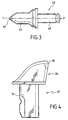
- the peak 30 comprises a base 32 of mounting on the drum and an active part 34 fitted with a carbide 36.
- Such a milling peak lends itself well to excavation in relatively sticky soils because it has a shape slender, sticky terrains having less tendency to stick to the peak milling.
- these peaks are not very suitable for excavations in hard ground of made of their relatively limited mechanical resistance.
- milling peaks such as the pick are used. 40 shown in FIG. 3. These peaks include a base 42 of substantially cylindrical mounting and an active part 44 which is substantially conical. The end of the active part 44 ends also by a carbide pad 46.
- peaks of the type shown in FIG. 3 Due to its more stocky shape, peaks of the type shown in FIG. 3 have a higher mechanical resistance and therefore allow you to work in harder terrain. Furthermore, because that their mounting base 42 on the drum is cylindrical, the action of milling peak is accompanied by a rotational movement around their longitudinal axis Y, Y 'achieving a self-sharpening effect of the tool. In however, due to their relatively stocky shape, they tend to block sticky surfaces and are therefore unsuitable for this kind of ground.
- the "blockage" of the sticky ground results in particular from the fact that the milling peaks such as the peaks 40 shown in Figure 3 are mounted on drums which consist of a solid ferrule which surrounds the hydraulic motors and thus promotes the accumulation of sticky materials around the drums in the form of ferrules between the peaks milling thus significantly reducing the efficiency of the latter.
- An object of the present invention is therefore to provide a tool for milling of the type mentioned above which is suitable for both work in hard ground and work in sticky ground.
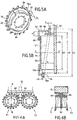
- FIG. 5B we have represented a hydraulic motor 50 fixed on a plate 52 secured to the body of the milling tool.
- This hydraulic motor has an axis X, X ' and its outer casing has a diameter D3.
- the motor output 50 is constituted by a rotary plate 54 around the axis X, X '.
- the drum constituted by a ferrule and serving to the attachment of the milling members, used in known tools, is replaced by the structure which will now be described.
- the milling members are fixed to a rim 56 which, in this embodiment, has the shape of an ellipse inclined relative to the axis X, X 'of the motor.
- This rim has an outer rim 56a of diameter D1 and an inner edge 56b of diameter D2. The difference between the diameters D1 and D2 is defined so that the rim has the necessary mechanical resistance.
- the rim 56 has a thickness e along the direction of the axis X, X 'which is much less than the length L of the hydraulic motor 50. This thickness e is at most equal to 1/4 th of the length of the motor 50.
- the outer edge 56a is preferably constituted by a succession of inclined faces 58 used for fixing the drilling members 40, in order to give them a favorable orientation.
- the device for rotating the milling members 40 also comprises a fixing hub 60 which is screwed onto the outlet plate 54 of the hydraulic motor.
- the hub 60 is connected to the rim 56 by securing members in the form of bent arms such as 62 extending in radial directions relative to the axis XX '. In the example more particularly described, four arms 62 are provided, but this number could be different.
- the arms 62 have different dimensions to adapt to the fact that the rim 56 has the shape of an ellipse E'1 inclined relative to the axis X, X 'while the hub 60 is orthogonal to this axis X, X '.
- the milling members or peaks 40 are fixed on a rim 56 of reduced thickness e , this thickness being of course adapted to the mechanical resistance that this rim must develop.
- this thickness e is much less than the length L of the hydraulic motor and is therefore much less than the length of the drum carrying the milling members in the solutions of the prior art. It is understood that thus, even if the material excavated from the ground is sticky, it will not be retained by the outer edge 56a of the rim and may flow to the engine where it will be taken up by the scraper 66 and directed towards the tubing. suction 22.
- milling 40 which are particularly well suited to work in a hard ground.
- the milling tool according to the invention is therefore well suited both to work in sticky terrain, since the accumulation of sticky material on the cutter is avoided and at work in hard ground, since it allows the use of milling bodies 40 adapted to such terrain.
- it also allows the fixing of milling members on the rim according to an ellipse which therefore allows cover the entire width of the trench by the milling elements while allowing the installation of a scraper between the engine and the rim.
- FIGS. 6A and 6B the entire part has been represented. of the milling tool. It includes four strawberries of the type shown in Figures 5A and 5B. On each side of the plate 52, we finds two cutters F1, F2 and F3, F4, each cutter being equipped with a scraper attached to plate 52.
- Figures 7A to 7C show three other possible forms of rim and therefore three other possible configurations of the organs or peaks of milling. In these figures, we have diagrammed by a single line the joints for fixing the milling members to the rim.
- the rim is consisting of two parts 70 and 72, each rim part having the shape of an ellipse.
- the ellipses are parallel to each other and inclined by relative to the axis XX 'of the motor which drives them in rotation.
- the part of rim 70 is connected to the hub 60 by the arms 62, the rim part 72 being connected to the rim part 70 by extensions of the arms 62 parallel to the axis XX 'and not shown in the figure.
- FIG. 7B differs from that of FIG. 7A by the fact that the rim parts 70 ′ and 72 ′, which are ellipses, are inclined and are symmetrical with respect to a plane orthogonal to the axis XX 'of the motor. As in the embodiment of FIG. 7A, the two rim parts 70 'and 72' are interconnected by extensions of the arms 62.
- the rim 74 is in a single part which has the shape of a portion of propeller of axis XX '.
- the rim 74 is mechanically connected to hub 60 by arms 62, the dimensions are adapted to the point of the propeller 74 where they are connected.
Landscapes
- Engineering & Computer Science (AREA)
- Mechanical Engineering (AREA)
- Mining & Mineral Resources (AREA)
- Civil Engineering (AREA)
- General Engineering & Computer Science (AREA)
- Structural Engineering (AREA)
- Earth Drilling (AREA)
- Shovels (AREA)
- Milling Processes (AREA)
- Tires In General (AREA)
Applications Claiming Priority (2)
| Application Number | Priority Date | Filing Date | Title |
|---|---|---|---|
| FR0100854 | 2001-01-23 | ||
| FR0100854A FR2819834B1 (fr) | 2001-01-23 | 2001-01-23 | Outil de fraisage pour la coupe de terrains durs et de terrains collants |
Publications (2)
| Publication Number | Publication Date |
|---|---|
| EP1231327A1 true EP1231327A1 (de) | 2002-08-14 |
| EP1231327B1 EP1231327B1 (de) | 2008-03-26 |
Family
ID=8859115
Family Applications (1)
| Application Number | Title | Priority Date | Filing Date |
|---|---|---|---|
| EP02290094A Expired - Lifetime EP1231327B1 (de) | 2001-01-23 | 2002-01-15 | Fräswerkzeug zum Schneiden von hartem Boden und von klebrigem Boden |
Country Status (8)
| Country | Link |
|---|---|
| EP (1) | EP1231327B1 (de) |
| JP (1) | JP4087607B2 (de) |
| AT (1) | ATE390523T1 (de) |
| DE (1) | DE60225740T2 (de) |
| ES (1) | ES2304420T3 (de) |
| FR (1) | FR2819834B1 (de) |
| HK (1) | HK1050228B (de) |
| PT (1) | PT1231327E (de) |
Cited By (3)
| Publication number | Priority date | Publication date | Assignee | Title |
|---|---|---|---|---|
| US6944977B2 (en) | 2003-01-08 | 2005-09-20 | Compagnie Du Sol | Drum for an excavator that can be used in particular for the production of vertical trenches in hard or very hard soils |
| EP2028319A1 (de) * | 2007-08-23 | 2009-02-25 | BAUER Maschinen GmbH | Fräsvorrichtung zur Bodenbearbeitung |
| CN112726708A (zh) * | 2020-12-24 | 2021-04-30 | 河海大学 | 一种带侧缘挡板的滚轮式防渗墙成槽注浆设备及施工方法 |
Families Citing this family (4)
| Publication number | Priority date | Publication date | Assignee | Title |
|---|---|---|---|---|
| FR2856088B1 (fr) | 2003-06-11 | 2005-09-09 | Cie Du Sol | Outil de fraisage pour la realisation de tranchees, permettant un changement rapide de la tete de coupe |
| FR2904338B1 (fr) * | 2006-07-28 | 2011-03-04 | Cie Du Sol | Tete de coupe pour machine d'excavation |
| FR2904339B1 (fr) * | 2006-07-28 | 2011-03-04 | Cie Du Sol | Tete de coupe pour une machine d'excavation |
| FR2914331B1 (fr) * | 2007-03-28 | 2009-07-03 | Cie Du Sol Soc Civ Ile | Tete de coupe pour une machine de decoupe du sol a fraises rotatives |
Citations (8)
| Publication number | Priority date | Publication date | Assignee | Title |
|---|---|---|---|---|
| US2752142A (en) * | 1951-09-25 | 1956-06-26 | Joy Mfg Co | Disintegrating head mechanism for a mining apparatus |
| US3279856A (en) * | 1963-11-18 | 1966-10-18 | Westinghouse Air Brake Co | Core breaker for ripper type miner |
| US3894587A (en) * | 1972-12-14 | 1975-07-15 | Hydrosol | Device for drilling in hard rock formation |
| US4991322A (en) * | 1989-01-13 | 1991-02-12 | Soletanche | Device for affixing cutter drums to an apparatus intended for cutting trenches in the ground |
| DE3926976A1 (de) * | 1989-08-16 | 1991-02-21 | Hochtief Ag Hoch Tiefbauten | Vorrichtung zum einbringen eines im wesentlichen vertikalen bodenschlitzes |
| JPH0396516A (ja) * | 1989-09-07 | 1991-04-22 | Taisei Corp | 可変幅掘削機及び拡幅掘削法 |
| JPH0579272A (ja) * | 1991-09-13 | 1993-03-30 | Nippon Kensetsu Kikaika Kyokai | 地盤掘削用チエーンカツタの潤滑性付与方法 |
| DE19539249A1 (de) * | 1994-10-21 | 1996-04-25 | Casagrande Spa | Fräse mit Abstützbuchse |
-
2001
- 2001-01-23 FR FR0100854A patent/FR2819834B1/fr not_active Expired - Fee Related
-
2002
- 2002-01-15 PT PT02290094T patent/PT1231327E/pt unknown
- 2002-01-15 AT AT02290094T patent/ATE390523T1/de not_active IP Right Cessation
- 2002-01-15 DE DE60225740T patent/DE60225740T2/de not_active Expired - Lifetime
- 2002-01-15 ES ES02290094T patent/ES2304420T3/es not_active Expired - Lifetime
- 2002-01-15 EP EP02290094A patent/EP1231327B1/de not_active Expired - Lifetime
- 2002-01-23 JP JP2002014434A patent/JP4087607B2/ja not_active Expired - Lifetime
-
2003
- 2003-01-15 HK HK03100362.7A patent/HK1050228B/zh not_active IP Right Cessation
Patent Citations (8)
| Publication number | Priority date | Publication date | Assignee | Title |
|---|---|---|---|---|
| US2752142A (en) * | 1951-09-25 | 1956-06-26 | Joy Mfg Co | Disintegrating head mechanism for a mining apparatus |
| US3279856A (en) * | 1963-11-18 | 1966-10-18 | Westinghouse Air Brake Co | Core breaker for ripper type miner |
| US3894587A (en) * | 1972-12-14 | 1975-07-15 | Hydrosol | Device for drilling in hard rock formation |
| US4991322A (en) * | 1989-01-13 | 1991-02-12 | Soletanche | Device for affixing cutter drums to an apparatus intended for cutting trenches in the ground |
| DE3926976A1 (de) * | 1989-08-16 | 1991-02-21 | Hochtief Ag Hoch Tiefbauten | Vorrichtung zum einbringen eines im wesentlichen vertikalen bodenschlitzes |
| JPH0396516A (ja) * | 1989-09-07 | 1991-04-22 | Taisei Corp | 可変幅掘削機及び拡幅掘削法 |
| JPH0579272A (ja) * | 1991-09-13 | 1993-03-30 | Nippon Kensetsu Kikaika Kyokai | 地盤掘削用チエーンカツタの潤滑性付与方法 |
| DE19539249A1 (de) * | 1994-10-21 | 1996-04-25 | Casagrande Spa | Fräse mit Abstützbuchse |
Non-Patent Citations (2)
| Title |
|---|
| PATENT ABSTRACTS OF JAPAN vol. 015, no. 279 (M - 1136) 16 July 1991 (1991-07-16) * |
| PATENT ABSTRACTS OF JAPAN vol. 017, no. 407 (M - 1454) 29 July 1993 (1993-07-29) * |
Cited By (3)
| Publication number | Priority date | Publication date | Assignee | Title |
|---|---|---|---|---|
| US6944977B2 (en) | 2003-01-08 | 2005-09-20 | Compagnie Du Sol | Drum for an excavator that can be used in particular for the production of vertical trenches in hard or very hard soils |
| EP2028319A1 (de) * | 2007-08-23 | 2009-02-25 | BAUER Maschinen GmbH | Fräsvorrichtung zur Bodenbearbeitung |
| CN112726708A (zh) * | 2020-12-24 | 2021-04-30 | 河海大学 | 一种带侧缘挡板的滚轮式防渗墙成槽注浆设备及施工方法 |
Also Published As
| Publication number | Publication date |
|---|---|
| HK1050228A1 (en) | 2003-06-13 |
| JP4087607B2 (ja) | 2008-05-21 |
| DE60225740D1 (de) | 2008-05-08 |
| FR2819834B1 (fr) | 2003-04-04 |
| JP2002256588A (ja) | 2002-09-11 |
| PT1231327E (pt) | 2008-07-01 |
| HK1050228B (zh) | 2008-07-11 |
| EP1231327B1 (de) | 2008-03-26 |
| DE60225740T2 (de) | 2009-04-16 |
| FR2819834A1 (fr) | 2002-07-26 |
| ATE390523T1 (de) | 2008-04-15 |
| ES2304420T3 (es) | 2008-10-16 |
Similar Documents
| Publication | Publication Date | Title |
|---|---|---|
| FR2849662A1 (fr) | Tambour pour fraise utilisable notamment pour la realisation de tranchees verticales dans des sols durs ou tres durs | |
| EP1231327B1 (de) | Fräswerkzeug zum Schneiden von hartem Boden und von klebrigem Boden | |
| FR2903035A1 (fr) | Perfectionnement aux outils d'usinage rotatifs, en particulier de type outil rotatif coupant, apte a optimiser la prise en charge de poussieres et copeaux par un dispositif de captage. | |
| EP1975323B1 (de) | Schneidkopf für eine Bodenschneidemaschine mit rotierenden Fräsen | |
| EP0258122B1 (de) | Fräsvorrichtung zum Ausheben von Graben im Boden | |
| EP0263762B1 (de) | Fräsvorrichtung zum Ausheben von Gräben im Boden | |
| EP1882782B1 (de) | Fräskopf für ein Erdaushubgerät | |
| EP0470990B1 (de) | Drehende Scheibe für einen Scheibenpflug | |
| EP0253726B1 (de) | Vorrichtung zum Ausheben von Gräben mit Fräsern | |
| EP0601624B1 (de) | Aerodynamisches Lager mit Flüssigkeitsfilm | |
| FR2732051A1 (fr) | Roue trancheuse | |
| EP0378485B1 (de) | Vorrichtung zum Befestigen von Frästrommeln an einem Baggergerät,das für das Ausheben von Gräben im Boden bestimmt ist | |
| EP0471719B1 (de) | Frei rotierende scheibe für scheibenpflug | |
| FR2686030A1 (fr) | Couteau tournant pour machines de coupe de vegetaux, notamment pour broyeur forestier. | |
| EP1350893B1 (de) | Fräsrad und Schlitzwandfräse umfassend mindestens zwei Fräsräder | |
| EP4098099B1 (de) | Vorrichtung zum mähen oder mulchen | |
| EP0760257B1 (de) | Schervorrichtung für verschiedenartige Körper | |
| FR2498043A1 (fr) | Engin de debroussaillement et de defrichage, comportant des outils rotatifs | |
| FR2778215A1 (fr) | Agencement d'arbre, agencement d'arbre et de moyeux, et faucheuse a disques | |
| FR2667758A1 (fr) | Barre de coupe pour fauchage a montage frontal. | |
| FR2646747A1 (fr) | Disque de labour du type destine a etre monte libre en rotation sur un axe solidaire du chassis d'une charrue | |
| FR2605491A1 (fr) | Outil de debroussaillement et d'abattage forestier | |
| EP3906971A1 (de) | Schutzvorrichtung für seil und schutzsystem | |
| EP3715583A1 (de) | Abreinigung einer auslassöffnung eines tunnelbohrers durch ultraschallwellen | |
| FR2842841A1 (fr) | Outil d'excavation pour pelleteuse hydraulique |
Legal Events
| Date | Code | Title | Description |
|---|---|---|---|
| PUAI | Public reference made under article 153(3) epc to a published international application that has entered the european phase |
Free format text: ORIGINAL CODE: 0009012 |
|
| AK | Designated contracting states |
Kind code of ref document: A1 Designated state(s): AT BE CH CY DE DK ES FI FR GB GR IE IT LI LU MC NL PT SE TR |
|
| AX | Request for extension of the european patent |
Free format text: AL;LT;LV;MK;RO;SI |
|
| 17P | Request for examination filed |
Effective date: 20021118 |
|
| AKX | Designation fees paid |
Designated state(s): AT BE CH CY DE DK ES FI FR GB GR IE IT LI LU MC NL PT SE TR |
|
| GRAP | Despatch of communication of intention to grant a patent |
Free format text: ORIGINAL CODE: EPIDOSNIGR1 |
|
| GRAS | Grant fee paid |
Free format text: ORIGINAL CODE: EPIDOSNIGR3 |
|
| GRAA | (expected) grant |
Free format text: ORIGINAL CODE: 0009210 |
|
| AK | Designated contracting states |
Kind code of ref document: B1 Designated state(s): AT BE CH CY DE DK ES FI FR GB GR IE IT LI LU MC NL PT SE TR |
|
| REG | Reference to a national code |
Ref country code: GB Ref legal event code: FG4D Free format text: NOT ENGLISH |
|
| RIN1 | Information on inventor provided before grant (corrected) |
Inventor name: CHAGNOT, PHILIPPE |
|
| REG | Reference to a national code |
Ref country code: IE Ref legal event code: FG4D Free format text: LANGUAGE OF EP DOCUMENT: FRENCH Ref country code: CH Ref legal event code: EP |
|
| REF | Corresponds to: |
Ref document number: 60225740 Country of ref document: DE Date of ref document: 20080508 Kind code of ref document: P |
|
| REG | Reference to a national code |
Ref country code: PT Ref legal event code: SC4A Free format text: AVAILABILITY OF NATIONAL TRANSLATION Effective date: 20080620 |
|
| REG | Reference to a national code |
Ref country code: HK Ref legal event code: GR Ref document number: 1050228 Country of ref document: HK |
|
| PG25 | Lapsed in a contracting state [announced via postgrant information from national office to epo] |
Ref country code: FI Free format text: LAPSE BECAUSE OF FAILURE TO SUBMIT A TRANSLATION OF THE DESCRIPTION OR TO PAY THE FEE WITHIN THE PRESCRIBED TIME-LIMIT Effective date: 20080326 |
|
| REG | Reference to a national code |
Ref country code: CH Ref legal event code: NV Representative=s name: MICHELI & CIE SA |
|
| PG25 | Lapsed in a contracting state [announced via postgrant information from national office to epo] |
Ref country code: AT Free format text: LAPSE BECAUSE OF FAILURE TO SUBMIT A TRANSLATION OF THE DESCRIPTION OR TO PAY THE FEE WITHIN THE PRESCRIBED TIME-LIMIT Effective date: 20080326 |
|
| NLV1 | Nl: lapsed or annulled due to failure to fulfill the requirements of art. 29p and 29m of the patents act | ||
| REG | Reference to a national code |
Ref country code: ES Ref legal event code: FG2A Ref document number: 2304420 Country of ref document: ES Kind code of ref document: T3 |
|
| PG25 | Lapsed in a contracting state [announced via postgrant information from national office to epo] |
Ref country code: SE Free format text: LAPSE BECAUSE OF FAILURE TO SUBMIT A TRANSLATION OF THE DESCRIPTION OR TO PAY THE FEE WITHIN THE PRESCRIBED TIME-LIMIT Effective date: 20080626 |
|
| PG25 | Lapsed in a contracting state [announced via postgrant information from national office to epo] |
Ref country code: NL Free format text: LAPSE BECAUSE OF FAILURE TO SUBMIT A TRANSLATION OF THE DESCRIPTION OR TO PAY THE FEE WITHIN THE PRESCRIBED TIME-LIMIT Effective date: 20080326 |
|
| PG25 | Lapsed in a contracting state [announced via postgrant information from national office to epo] |
Ref country code: DK Free format text: LAPSE BECAUSE OF FAILURE TO SUBMIT A TRANSLATION OF THE DESCRIPTION OR TO PAY THE FEE WITHIN THE PRESCRIBED TIME-LIMIT Effective date: 20080326 |
|
| PLBE | No opposition filed within time limit |
Free format text: ORIGINAL CODE: 0009261 |
|
| STAA | Information on the status of an ep patent application or granted ep patent |
Free format text: STATUS: NO OPPOSITION FILED WITHIN TIME LIMIT |
|
| 26N | No opposition filed |
Effective date: 20081230 |
|
| PG25 | Lapsed in a contracting state [announced via postgrant information from national office to epo] |
Ref country code: CY Free format text: LAPSE BECAUSE OF FAILURE TO SUBMIT A TRANSLATION OF THE DESCRIPTION OR TO PAY THE FEE WITHIN THE PRESCRIBED TIME-LIMIT Effective date: 20080326 |
|
| PG25 | Lapsed in a contracting state [announced via postgrant information from national office to epo] |
Ref country code: GR Free format text: LAPSE BECAUSE OF FAILURE TO SUBMIT A TRANSLATION OF THE DESCRIPTION OR TO PAY THE FEE WITHIN THE PRESCRIBED TIME-LIMIT Effective date: 20080627 |
|
| PGFP | Annual fee paid to national office [announced via postgrant information from national office to epo] |
Ref country code: PT Payment date: 20101221 Year of fee payment: 10 |
|
| PG25 | Lapsed in a contracting state [announced via postgrant information from national office to epo] |
Ref country code: LU Free format text: LAPSE BECAUSE OF NON-PAYMENT OF DUE FEES Effective date: 20090115 |
|
| PGFP | Annual fee paid to national office [announced via postgrant information from national office to epo] |
Ref country code: CH Payment date: 20110113 Year of fee payment: 10 |
|
| PG25 | Lapsed in a contracting state [announced via postgrant information from national office to epo] |
Ref country code: TR Free format text: LAPSE BECAUSE OF FAILURE TO SUBMIT A TRANSLATION OF THE DESCRIPTION OR TO PAY THE FEE WITHIN THE PRESCRIBED TIME-LIMIT Effective date: 20080326 |
|
| PGFP | Annual fee paid to national office [announced via postgrant information from national office to epo] |
Ref country code: IE Payment date: 20111223 Year of fee payment: 11 |
|
| PGFP | Annual fee paid to national office [announced via postgrant information from national office to epo] |
Ref country code: BE Payment date: 20120126 Year of fee payment: 11 |
|
| REG | Reference to a national code |
Ref country code: PT Ref legal event code: MM4A Free format text: LAPSE DUE TO NON-PAYMENT OF FEES Effective date: 20120716 |
|
| REG | Reference to a national code |
Ref country code: CH Ref legal event code: PL |
|
| PG25 | Lapsed in a contracting state [announced via postgrant information from national office to epo] |
Ref country code: CH Free format text: LAPSE BECAUSE OF NON-PAYMENT OF DUE FEES Effective date: 20120131 Ref country code: LI Free format text: LAPSE BECAUSE OF NON-PAYMENT OF DUE FEES Effective date: 20120131 |
|
| PG25 | Lapsed in a contracting state [announced via postgrant information from national office to epo] |
Ref country code: PT Free format text: LAPSE BECAUSE OF NON-PAYMENT OF DUE FEES Effective date: 20120716 |
|
| BERE | Be: lapsed |
Owner name: CIE DU SOL Effective date: 20130131 |
|
| REG | Reference to a national code |
Ref country code: IE Ref legal event code: MM4A |
|
| PG25 | Lapsed in a contracting state [announced via postgrant information from national office to epo] |
Ref country code: BE Free format text: LAPSE BECAUSE OF NON-PAYMENT OF DUE FEES Effective date: 20130131 |
|
| PG25 | Lapsed in a contracting state [announced via postgrant information from national office to epo] |
Ref country code: IE Free format text: LAPSE BECAUSE OF NON-PAYMENT OF DUE FEES Effective date: 20130115 |
|
| REG | Reference to a national code |
Ref country code: FR Ref legal event code: PLFP Year of fee payment: 15 |
|
| PGFP | Annual fee paid to national office [announced via postgrant information from national office to epo] |
Ref country code: GB Payment date: 20151224 Year of fee payment: 15 |
|
| PGFP | Annual fee paid to national office [announced via postgrant information from national office to epo] |
Ref country code: ES Payment date: 20160114 Year of fee payment: 15 |
|
| REG | Reference to a national code |
Ref country code: FR Ref legal event code: PLFP Year of fee payment: 16 |
|
| GBPC | Gb: european patent ceased through non-payment of renewal fee |
Effective date: 20170115 |
|
| PG25 | Lapsed in a contracting state [announced via postgrant information from national office to epo] |
Ref country code: GB Free format text: LAPSE BECAUSE OF NON-PAYMENT OF DUE FEES Effective date: 20170115 |
|
| REG | Reference to a national code |
Ref country code: FR Ref legal event code: PLFP Year of fee payment: 17 |
|
| PG25 | Lapsed in a contracting state [announced via postgrant information from national office to epo] |
Ref country code: ES Free format text: LAPSE BECAUSE OF NON-PAYMENT OF DUE FEES Effective date: 20170116 |
|
| REG | Reference to a national code |
Ref country code: ES Ref legal event code: FD2A Effective date: 20181114 |
|
| PGFP | Annual fee paid to national office [announced via postgrant information from national office to epo] |
Ref country code: MC Payment date: 20191224 Year of fee payment: 19 |
|
| PGFP | Annual fee paid to national office [announced via postgrant information from national office to epo] |
Ref country code: FR Payment date: 20191219 Year of fee payment: 19 |
|
| PGFP | Annual fee paid to national office [announced via postgrant information from national office to epo] |
Ref country code: IT Payment date: 20200102 Year of fee payment: 19 Ref country code: DE Payment date: 20191218 Year of fee payment: 19 |
|
| REG | Reference to a national code |
Ref country code: DE Ref legal event code: R119 Ref document number: 60225740 Country of ref document: DE |
|
| PG25 | Lapsed in a contracting state [announced via postgrant information from national office to epo] |
Ref country code: MC Free format text: LAPSE BECAUSE OF NON-PAYMENT OF DUE FEES Effective date: 20210201 |
|
| PG25 | Lapsed in a contracting state [announced via postgrant information from national office to epo] |
Ref country code: FR Free format text: LAPSE BECAUSE OF NON-PAYMENT OF DUE FEES Effective date: 20210131 |
|
| PG25 | Lapsed in a contracting state [announced via postgrant information from national office to epo] |
Ref country code: DE Free format text: LAPSE BECAUSE OF NON-PAYMENT OF DUE FEES Effective date: 20210803 |
|
| PG25 | Lapsed in a contracting state [announced via postgrant information from national office to epo] |
Ref country code: IT Free format text: LAPSE BECAUSE OF NON-PAYMENT OF DUE FEES Effective date: 20210115 |