EP1228992A1 - Schwenkbarer Anschlag für einen Registerarm - Google Patents
Schwenkbarer Anschlag für einen Registerarm Download PDFInfo
- Publication number
- EP1228992A1 EP1228992A1 EP02001169A EP02001169A EP1228992A1 EP 1228992 A1 EP1228992 A1 EP 1228992A1 EP 02001169 A EP02001169 A EP 02001169A EP 02001169 A EP02001169 A EP 02001169A EP 1228992 A1 EP1228992 A1 EP 1228992A1
- Authority
- EP
- European Patent Office
- Prior art keywords
- signature
- stop block
- pressure roller
- moved
- alignment
- Prior art date
- Legal status (The legal status is an assumption and is not a legal conclusion. Google has not performed a legal analysis and makes no representation as to the accuracy of the status listed.)
- Granted
Links
Images




Classifications
-
- B—PERFORMING OPERATIONS; TRANSPORTING
- B65—CONVEYING; PACKING; STORING; HANDLING THIN OR FILAMENTARY MATERIAL
- B65H—HANDLING THIN OR FILAMENTARY MATERIAL, e.g. SHEETS, WEBS, CABLES
- B65H9/00—Registering, e.g. orientating, articles; Devices therefor
- B65H9/12—Registering, e.g. orientating, articles; Devices therefor carried by article grippers
-
- B—PERFORMING OPERATIONS; TRANSPORTING
- B65—CONVEYING; PACKING; STORING; HANDLING THIN OR FILAMENTARY MATERIAL
- B65H—HANDLING THIN OR FILAMENTARY MATERIAL, e.g. SHEETS, WEBS, CABLES
- B65H5/00—Feeding articles separated from piles; Feeding articles to machines
- B65H5/08—Feeding articles separated from piles; Feeding articles to machines by grippers, e.g. suction grippers
- B65H5/12—Revolving grippers, e.g. mounted on arms, frames or cylinders
-
- B—PERFORMING OPERATIONS; TRANSPORTING
- B65—CONVEYING; PACKING; STORING; HANDLING THIN OR FILAMENTARY MATERIAL
- B65H—HANDLING THIN OR FILAMENTARY MATERIAL, e.g. SHEETS, WEBS, CABLES
- B65H9/00—Registering, e.g. orientating, articles; Devices therefor
- B65H9/06—Movable stops or gauges, e.g. rising and falling front stops
-
- B—PERFORMING OPERATIONS; TRANSPORTING
- B65—CONVEYING; PACKING; STORING; HANDLING THIN OR FILAMENTARY MATERIAL
- B65H—HANDLING THIN OR FILAMENTARY MATERIAL, e.g. SHEETS, WEBS, CABLES
- B65H2404/00—Parts for transporting or guiding the handled material
- B65H2404/10—Rollers
- B65H2404/15—Roller assembly, particular roller arrangement
- B65H2404/152—Arrangement of roller on a movable frame
- B65H2404/1521—Arrangement of roller on a movable frame rotating, pivoting or oscillating around an axis, e.g. parallel to the roller axis
- B65H2404/15212—Arrangement of roller on a movable frame rotating, pivoting or oscillating around an axis, e.g. parallel to the roller axis rotating, pivoting or oscillating around an axis perpendicular to the roller axis
-
- B—PERFORMING OPERATIONS; TRANSPORTING
- B65—CONVEYING; PACKING; STORING; HANDLING THIN OR FILAMENTARY MATERIAL
- B65H—HANDLING THIN OR FILAMENTARY MATERIAL, e.g. SHEETS, WEBS, CABLES
- B65H2404/00—Parts for transporting or guiding the handled material
- B65H2404/10—Rollers
- B65H2404/15—Roller assembly, particular roller arrangement
- B65H2404/153—Arrangements of rollers facing a transport surface
- B65H2404/1531—Arrangements of rollers facing a transport surface the transport surface being a cylinder
Definitions
- the present invention relates to an apparatus and a method for alignment a signature according to the preamble of claims of claims 1 and 5.
- a signature is a printed sheet that is folded at least once, but can also be from a group of printed sheets exist that have been folded together at least once.
- a group of signatures is generally held in a magazine of a feeder that the Contains signatures that make up the book or magazine. With some Processing operations, it is necessary to turn the signature. This is usually Turning devices provided.
- a signature feeder is one Assigned turning device, in which the rear edge of a signature of Gripper elements are detected and withdrawn from the feed device.
- the Gripper elements are arranged on the circumference of a main drum and move them Signature along the surface of the drum to a register or registration stop. After the registration-accurate alignment of the signature, it is processed in the opposite direction moves along the surface of the main drum.
- the object of the present invention is to further develop such a device, to increase their versatility and performance.
- This task is accomplished by a device for aligning a signature with the Features solved according to claim 1. With regard to the procedure, the task solved by a method with the features according to claim 5.
- An alignment device for register-accurate alignment along A surface moved in a first direction accordingly comprises a signature Pressure roller to move the signature in the first direction and one Stop block to limit the forward movement of the signature, the Stop block is rotatable about an axis to adapt to a signature in To enable inclination.
- an invention comprises Alignment device for register accurate alignment along a surface in a first direction moving signature with a leading edge to a pressure roller Moving the signature forward in a first direction and a stop block with one Stop area for stopping the forward movement of the signature, the Stop block is rotatable about an axis to adjust the orientation of the Allow stopping area at an inclined position of the front edge of the signature.
- an alignment device for register-accurate alignment of a signature by a feed device a surface is moved in a first direction, comprises a pressure roller for Moving the signature forward in the first direction after the signature is released the feed device and a stop block to limit the Forward movement of the signature, wherein the stop block is rotatable about an axis to to allow an adjustment to an inclined position of the signature.
- an invention comprises Alignment device for register-accurate alignment of a signature by a Feed device is moved along a surface in a first direction Pressing and conveying device for moving the signature in the first direction after the signature has been released by the feed device by using the Moment of movement of the signature, and a stop block to limit the Forward movement of the signature, wherein the stop block is rotatable about an axis to to allow an adjustment to an inclined position of the signature.
- an alignment device for register-accurate alignment of a signature with a leading edge, the signature is moved along a surface in a first direction, includes a pressing and Conveyor for moving the signature in the first direction after the release of the Signature by the feed device by using the moment of movement Signature and a stop block with a stopping area for stopping the Forward movement of the signature, wherein the stop block is rotatable about an axis to an adjustment of the orientation of the stopping surface to an inclined position of the front edge of the Allow signature.
- An inventive method for register-accurate alignment of a signature Moving along a surface in a first direction provides that the signature is moved in the first direction by means of a pressure roller and that the Forward movement of the signature is limited by a stop block, the Stop block is rotatable about an axis to adjust the orientation of the Allow stopping area at an inclined position of the front edge of the signature.
- a pressure roller in a first direction is moved and the movement of the signature by means of a Stop block is limited, which is rotatable about an axis in order to adapt to a Allow the leading edge of the signature to slant.
- Another method according to the invention for register-accurate alignment of a signature with a leading edge which is fed in along a surface by means of a feed device If a first direction is moved, the signature is provided by the feed device is released that the signature in the first direction by means of a pressure roller is moved and that the forward movement of the signature by means of a stop block is limited, which is rotatable about an axis in order to adapt to an inclined position Allow leading edge of the signature.
- a method for register-accurate alignment of a signature with a Front edge which is fed into a first along a surface by means of a feed device Direction is moved, provided that the signature from the feed device is released, is moved in the first direction by means of a pressure roller and at which limits the forward movement of the signature by means of a stop block which is rotatable about an axis to adapt to an inclined position of the front edge of the To enable signature, and in which the signature is moved in a second direction.
- a surface is moved in a first direction, it is provided that the signature of the feed device is released by means of a pressure roller in the first Direction is moved and that the movement of the signature by means of a stop block is limited, which is rotatable about an axis in order to adapt to an inclined position Allow leading edge of the signature.
- Another embodiment of a method according to the invention for register-accurate Align a signature using a feed device along a surface is moved in a first direction, provides that the signature of the Feed device is released that the signature by means of a pressure roller the first direction is moved, that the movement of the signature by means of a Stop block is limited, which is rotatable about an axis in order to adapt to a Allow the leading edge of the signature to slant and that the signature into a second direction is moved.
- a method according to the invention for register-accurate alignment of a Signature created by means of a feed device along a surface in a first Direction which provides that the signature of the Feed device is released that the signature by means of a pressure and Conveyor device using the moment of movement of the signature in the first Is moved and that the forward movement of the signature by means of a Stop block is limited, which is rotatable about an axis in order to adapt to a To enable the signature to be tilted.
- Fig. 1 shows a signature feeder 100, as used in the graphics industry, e.g. B. can be used in a printing press, a saddle stitcher or the like.
- the Feed device 100 comprises a magazine 102, in which signatures from the bottom of a Stack are subtracted.
- a gripper (not shown) moves the individual signatures 106 around the peripheral surface 108 of a main drum 110 in an alignment device 112.
- the alignment device 112 comprises a pressure roller arrangement 116 and one Stop block 122.
- the pressure roller arm 118 is about an axis 123 pivotable.
- a signature 106 moves into the circumference of the main drum shown direction and is detected by the alignment device 112.
- the pressure roller 116 exerts pressure on the signature 106 in a pressure gap.
- the signature 106 is from of the gripping device and released by the moment of movement of the signature 106 and the pressure roller 116 moves further into the stop block 122.
- the stop block 122 is used to align and stop the signature 106.
- the alignment stop and the Stop block 122 are pivotable or rotatable about an axis 126.
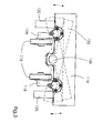
- Fig. 3 shows a part of the alignment device 112 with its pressure rollers 116, the are rotatably connected to pressure roller arms 118.
- the pressure roller arms 118 are connected to the pressure roller block 119, which is pivotable and rotatable. How through that Dashed lines are indicated, the stop block 122 and the stop arms 120 rotatable about a pivot point 126, whereby when the signature 106 is inclined the main drum 110 rotates the stop and the stop block 122 is made possible.
- An inclination of the signature 106 can be intentional or unintentional occur for various reasons, especially if the two pressure rollers Do not press signature on main drum 110 with the same pressure.
- the entire system had to be adjusted to an inclined position of the signature Alignment arrangement including the pressure roller arrangement can be rotated.
- the stop block 122 and the stopper are rotated.
- the advantage of the invention is thus that the pressure roller 116 has the signature 106 presses more evenly into the alignment arrangement since the pressure roller 116 continues is aligned with the main drum 110. In known devices, this causes Rotate the entire alignment device so that the pressure rollers with respect to the Move the main drum, causing unwanted wrinkling or buckling of the Signature leads.
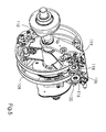
- FIG. 5, 6 and 7 show the alignment device 112 with a pressure roller 116, a Pressure roller arm 118, a pressure roller block 119, a stop arm 120 and a stop block 122.
- the stop roller arm is pivotable about an axis 123.
- the pressure roller 116 exerts pressure on the signature, so that between the Pressure roller 116 and drum 110 there is a pressure gap.
- the signature 106 is moved along the circumference of the main drum 110 in the direction shown and from the Pressure roller arrangement detected. Subsequently, the signature 106 from the Gripping device released, and the moment of movement of the signature 106 moves it forward into the stop block 122.
- the stop block 122 is used for alignment and Stop the signature.
- the alignment stop and the stop block 122 pivot or rotate about a point 126 with respect to the pressure roller assembly, which is a Rotation of the stop and the stop block 122 allows when one Signature 106, which is on the main drum 110 in an inclined position, pushed to it become. After alignment, the direction of movement of the signature 106 is changed or vice versa, and the signature 106 is moved in the opposite direction Circumference 108 of drum 110 moves.
- the alignment device according to the invention can also be used in conjunction with a signature can be used as a flat or otherwise arranged surface the round drum described here is moved.
Landscapes
- Engineering & Computer Science (AREA)
- Mechanical Engineering (AREA)
- Registering Or Overturning Sheets (AREA)
- Apparatus For Radiation Diagnosis (AREA)
- Bus Control (AREA)
- Load-Engaging Elements For Cranes (AREA)
Abstract
Description
- Fig. 1
- eine Seitenansicht einer erfindungsgemäßen Signaturen-Zuführvorrichtung mit einer Trommel und einer Ausrichtvorrichtung;
- Fig. 2
- eine schematische Seitenansicht einer erfindungsgemäßen Ausrichtvorrichtung mit einer Andrückwalze;
- Fig. 3
- eine schematische Draufsicht einer erfindungsgemäßen Ausrichtvorrichtung mit einer Andrückwalze;
- Fig. 4
- eine perspektivische Darstellung einer erfindungsgemäßen Ausrichtvorrichtung;
- Fig. 5
- eine perspektivische Darstellung einer erfindungsgemäßen Ausrichtvorrichtung mit einer Trommel;
- Fig. 6
- eine Draufsicht einer erfindungsgemäßen Ausrichtvorrichtung mit einer Trommel.
- 100
- Signaturen-Zuführeinrichtung
- 102
- Magazin
- 106
- Signatur
- 108
- Umfangsoberfläche
- 110
- Haupttrommel
- 112
- Ausrichtvorrichtung
- 116
- Andrückwalzenanordnung
- 118
- Andrückwalzenarm
- 119
- Andrückwalzenblock
- 120
- Ausrichtanschlagsarm
- 122
- Anschlagsblock
- 123
- Achse
- 126
- Schwenkachse
Claims (7)
- Vorrichtung zum Ausrichten einer Signatur (106), die entlang einer Oberfläche (108) bewegt wird,
gekennzeichnet durch
eine Andrückwalze (116) zum Vorwärtsbewegen der Signatur (106); und einen Anschlagsblock (122) zum Begrenzen der Vorwärtsbewegung der Signatur (106), wobei der Anschlagsblock (122) um eine Achse (126) drehbar ist, um eine Anpassung an eine Signatur (106), die sich in Schräglage befindet, zu ermöglichen. - Vorrichtung zum Ausrichten einer Signatur (106) nach Anspruch 1
dadurch gekennzeichnet, dass eine Mehrzahl von Ausrichtanschlagsarmen (120) vorgesehen ist. - Vereinzelungstrommel (110),
dadurch gekennzeichnet, dass auf der Oberfläche der Trommel eine Vorrichtung zum Ausrichten von Signaturen nach einem der Ansprüche 1 oder 2 vorgesehen ist. - Zuführeinrichtung, insbesondere Anleger,
gekennzeichnet durch
eine Vereinzelungstrommel (110) nach Anspruch 3. - Verfahren zum Ausrichten einer Signatur (106), die entlang einer Oberfläche (108) bewegt wird,
gekennzeichnet durch
die folgenden Schritte:Vorwärtsbewegen der Signatur (106) mittels einer Andrückwalze (116); undBegrenzen der Vorwärtsbewegung der Signatur (106) mittels eines Anschlagsblocks (122), der um eine Achse (126) drehbar ist, um eine Anpassung an eine Signatur (106), die sich in Schräglage befindet, zu ermöglichen. - Verfahren zum Ausrichten einer Signatur (106) nach Anspruch 5,
dadurch gekennzeichnet, dass die Signatur (106) von der Vorwärtsbewegung mittels der Andrückwalze durch eine Vorschubvorrichtung bewegt und von der Vorschubvorrichtung (110) freigegeben wird. - Verfahren zum Ausrichten einer Signatur (106) nach Anspruch 5 oder 6
dadurch gekennzeichnet, dass die Signatur (106) nach dem Begrenzen der Vorwärtsbewegung der Signatur (106) mittels des Anschlagsblocks (118) in die entgegengesetzte Richtung bewegt wird.
Applications Claiming Priority (2)
| Application Number | Priority Date | Filing Date | Title |
|---|---|---|---|
| US26572801P | 2001-02-01 | 2001-02-01 | |
| US265728P | 2001-02-01 |
Publications (2)
| Publication Number | Publication Date |
|---|---|
| EP1228992A1 true EP1228992A1 (de) | 2002-08-07 |
| EP1228992B1 EP1228992B1 (de) | 2003-10-01 |
Family
ID=23011658
Family Applications (1)
| Application Number | Title | Priority Date | Filing Date |
|---|---|---|---|
| EP02001169A Expired - Lifetime EP1228992B1 (de) | 2001-02-01 | 2002-01-28 | Schwenkbarer Anschlag für einen Registerarm |
Country Status (4)
| Country | Link |
|---|---|
| US (1) | US6592120B2 (de) |
| EP (1) | EP1228992B1 (de) |
| AT (1) | ATE251078T1 (de) |
| DE (2) | DE10203061A1 (de) |
Families Citing this family (2)
| Publication number | Priority date | Publication date | Assignee | Title |
|---|---|---|---|---|
| US8210104B2 (en) * | 2008-10-23 | 2012-07-03 | Eastman Kodak Company | Moveable printing plate registration member |
| US8176846B2 (en) * | 2008-10-23 | 2012-05-15 | Eastman Kodak Company | Printing plate positioning |
Citations (3)
| Publication number | Priority date | Publication date | Assignee | Title |
|---|---|---|---|---|
| US2251943A (en) * | 1940-05-15 | 1941-08-12 | Tw & Cb Sheridan Co | Signature gathering machine |
| US4706950A (en) * | 1986-01-06 | 1987-11-17 | K. S. Macey Machine Company, Inc. | Sheet gathering apparatus |
| US4844433A (en) * | 1988-04-11 | 1989-07-04 | R. R. Donnelley & Sons Company | Packer box undersized signature handling kit |
Family Cites Families (7)
| Publication number | Priority date | Publication date | Assignee | Title |
|---|---|---|---|---|
| US1340723A (en) * | 1917-12-15 | 1920-05-18 | Cottrell C B & Sons Co | Sheet-registering device |
| US1883471A (en) * | 1930-02-10 | 1932-10-18 | Miller Printing Machinery Co | Sheet detector |
| US5263705A (en) * | 1992-06-29 | 1993-11-23 | Pitney Bowes Inc. | Document registration apparatus with skew adjustment |
| US5253861A (en) * | 1992-08-28 | 1993-10-19 | Pitney Bowes Inc. | Document registration apparatus with improvement to prevent shingling during removal of documents |
| US5301938A (en) * | 1992-12-17 | 1994-04-12 | Xerox Corporation | Apparatus for gripping and registering sheets |
| DE19524891A1 (de) * | 1995-07-08 | 1997-01-09 | Heidelberger Druckmasch Ag | Vorrichtung zum seitlichen Ausrichten von Bögen im Anleger einer Bogenrotationsdruckmaschine |
| US5934668A (en) * | 1996-12-27 | 1999-08-10 | Pitney Bowes Inc. | Document registration apparatus with improved document drive capability |
-
2001
- 2001-08-20 US US09/933,029 patent/US6592120B2/en not_active Expired - Lifetime
-
2002
- 2002-01-26 DE DE10203061A patent/DE10203061A1/de not_active Withdrawn
- 2002-01-28 DE DE50200056T patent/DE50200056D1/de not_active Expired - Lifetime
- 2002-01-28 AT AT02001169T patent/ATE251078T1/de not_active IP Right Cessation
- 2002-01-28 EP EP02001169A patent/EP1228992B1/de not_active Expired - Lifetime
Patent Citations (3)
| Publication number | Priority date | Publication date | Assignee | Title |
|---|---|---|---|---|
| US2251943A (en) * | 1940-05-15 | 1941-08-12 | Tw & Cb Sheridan Co | Signature gathering machine |
| US4706950A (en) * | 1986-01-06 | 1987-11-17 | K. S. Macey Machine Company, Inc. | Sheet gathering apparatus |
| US4844433A (en) * | 1988-04-11 | 1989-07-04 | R. R. Donnelley & Sons Company | Packer box undersized signature handling kit |
Also Published As
| Publication number | Publication date |
|---|---|
| ATE251078T1 (de) | 2003-10-15 |
| US20020102120A1 (en) | 2002-08-01 |
| EP1228992B1 (de) | 2003-10-01 |
| DE10203061A1 (de) | 2002-08-08 |
| US6592120B2 (en) | 2003-07-15 |
| DE50200056D1 (de) | 2003-11-06 |
Similar Documents
| Publication | Publication Date | Title |
|---|---|---|
| DE4200406A1 (de) | Greifereinrichtung an bogenverarbeitenden maschinen | |
| EP0291721A2 (de) | Bogen-Rotationsdruckmaschine zur Herstellung von einseitigem Mehrfarbendruck oder Schön- und Widerdruck | |
| EP0708046A1 (de) | Registereinzugsvorrichtung | |
| EP0753407A2 (de) | Vorrichtung zum seitlichen Ausrichten von Bögen im Anleger einer Bogenrotationsdruckmaschine | |
| EP0606549B1 (de) | Vorrichtung zum Transportieren von flächigen Erzeugnissen | |
| DE10023940B4 (de) | Vorrichtung zum Ausrichten bogenförmigen Materials während des Transports | |
| DE3511897A1 (de) | Vorrichtung zum seitlichen ausrichten von bogen | |
| EP1939008A2 (de) | Sammelhefter mit variabler Kettenteilung | |
| DE4230218C2 (de) | Vorgreifer einer Bogendruckmaschine | |
| DE2438483B2 (de) | Verfahren und Vorrichtung zum Zuführen von Blättern zu einer Druckmaschine oder einem Vervielfältigungsgerät | |
| EP1588862A2 (de) | Vorrichtung zum arbeitstaktgerechten Zuführen von Buchblocks, Büchern oder dgl. Druckprodukte zu einer Weiterverarbeitungsmaschine | |
| DE60101962T2 (de) | Spleissvorrichtung zum spleissen von gummibeschichteten kordbandstreifen | |
| DE3114581C2 (de) | Fördervorrichtung für eine Bogen-Rotationsdruckmaschine | |
| EP1228992B1 (de) | Schwenkbarer Anschlag für einen Registerarm | |
| DE19901699B4 (de) | Verfahren und eine Vorrichtung zur Durchführung des Verfahrens zur Beseitigung von rhythmischen Passerfehlern in Rotationsdruckmaschinen | |
| EP0976553A2 (de) | Verfahren und Vorrichtung zur Übergabe der Hinterkante eines Bogens in einer Wendeeinrichtung einer Bogenrotationsdruckmaschine | |
| DE10023290A1 (de) | Ausrichteeinheit für bogenförmiges Material | |
| DE102007050449B4 (de) | Verfahren zum Ausrichten eines blattförmigen Mediums und Ausrichtvorrichtung für das Medium | |
| EP1561599A1 (de) | Einrichtung zur Herstellung von aus gefalzten Druckbogen bestehenden fadengehefteten Buchblocks | |
| DE102013220053B4 (de) | Auslage einer bogenverarbeitenden Maschine mit einem ersten Fördersystem mit von Zugmitteln umlaufend führbaren Vorderkantengreiferwagen und einem zweiten Fördersystem mit von Zugmitteln umlaufend führbaren Hinterkantengreiferwagen, Hinterkantengreiferwagen und Verfahren zum Transport von Bogen | |
| DE4016304A1 (de) | Vorrichtung zum ausrichten schuppenfoermig unterlappt gefoerderter bogen | |
| DE102022108914A1 (de) | Vorrichtung zum Positionieren eines Werkzeugs und Substratbogen verarbeitende Maschine und Verfahren zum Positionieren eines Werkzeugs | |
| DE10201382A1 (de) | Einstellbare Nadeln für eine Bogentrennvorrichtung | |
| EP0679593B1 (de) | Taktrolle zum Transport von Bogen in eine bogenverarbeitende Maschine | |
| EP0570339A1 (de) | Einrichtung zum klebeartigen Beiheften von Beilagen |
Legal Events
| Date | Code | Title | Description |
|---|---|---|---|
| PUAI | Public reference made under article 153(3) epc to a published international application that has entered the european phase |
Free format text: ORIGINAL CODE: 0009012 |
|
| 17P | Request for examination filed |
Effective date: 20020523 |
|
| AK | Designated contracting states |
Kind code of ref document: A1 Designated state(s): AT BE CH CY DE DK ES FI FR GB GR IE IT LI LU MC NL PT SE TR |
|
| AX | Request for extension of the european patent |
Free format text: AL;LT;LV;MK;RO;SI |
|
| 17Q | First examination report despatched |
Effective date: 20020927 |
|
| GRAH | Despatch of communication of intention to grant a patent |
Free format text: ORIGINAL CODE: EPIDOS IGRA |
|
| AKX | Designation fees paid |
Designated state(s): AT BE CH CY DE DK ES FI FR GB GR IE IT LI LU MC NL PT SE TR |
|
| GRAH | Despatch of communication of intention to grant a patent |
Free format text: ORIGINAL CODE: EPIDOS IGRA |
|
| GRAA | (expected) grant |
Free format text: ORIGINAL CODE: 0009210 |
|
| AK | Designated contracting states |
Kind code of ref document: B1 Designated state(s): AT BE CH CY DE DK ES FI FR GB GR IE IT LI LU MC NL PT SE TR |
|
| PG25 | Lapsed in a contracting state [announced via postgrant information from national office to epo] |
Ref country code: IT Free format text: LAPSE BECAUSE OF FAILURE TO SUBMIT A TRANSLATION OF THE DESCRIPTION OR TO PAY THE FEE WITHIN THE PRESCRIBED TIME-LIMIT;WARNING: LAPSES OF ITALIAN PATENTS WITH EFFECTIVE DATE BEFORE 2007 MAY HAVE OCCURRED AT ANY TIME BEFORE 2007. THE CORRECT EFFECTIVE DATE MAY BE DIFFERENT FROM THE ONE RECORDED. Effective date: 20031001 Ref country code: TR Free format text: LAPSE BECAUSE OF FAILURE TO SUBMIT A TRANSLATION OF THE DESCRIPTION OR TO PAY THE FEE WITHIN THE PRESCRIBED TIME-LIMIT Effective date: 20031001 Ref country code: FI Free format text: LAPSE BECAUSE OF FAILURE TO SUBMIT A TRANSLATION OF THE DESCRIPTION OR TO PAY THE FEE WITHIN THE PRESCRIBED TIME-LIMIT Effective date: 20031001 Ref country code: CY Free format text: LAPSE BECAUSE OF FAILURE TO SUBMIT A TRANSLATION OF THE DESCRIPTION OR TO PAY THE FEE WITHIN THE PRESCRIBED TIME-LIMIT Effective date: 20031001 Ref country code: ES Free format text: LAPSE BECAUSE OF FAILURE TO SUBMIT A TRANSLATION OF THE DESCRIPTION OR TO PAY THE FEE WITHIN THE PRESCRIBED TIME-LIMIT Effective date: 20031001 Ref country code: IE Free format text: LAPSE BECAUSE OF FAILURE TO SUBMIT A TRANSLATION OF THE DESCRIPTION OR TO PAY THE FEE WITHIN THE PRESCRIBED TIME-LIMIT Effective date: 20031001 Ref country code: NL Free format text: LAPSE BECAUSE OF FAILURE TO SUBMIT A TRANSLATION OF THE DESCRIPTION OR TO PAY THE FEE WITHIN THE PRESCRIBED TIME-LIMIT Effective date: 20031001 |
|
| REG | Reference to a national code |
Ref country code: GB Ref legal event code: FG4D Free format text: NOT ENGLISH |
|
| REG | Reference to a national code |
Ref country code: CH Ref legal event code: EP |
|
| REG | Reference to a national code |
Ref country code: IE Ref legal event code: FG4D Free format text: GERMAN |
|
| REF | Corresponds to: |
Ref document number: 50200056 Country of ref document: DE Date of ref document: 20031106 Kind code of ref document: P |
|
| GBT | Gb: translation of ep patent filed (gb section 77(6)(a)/1977) | ||
| PG25 | Lapsed in a contracting state [announced via postgrant information from national office to epo] |
Ref country code: GR Free format text: LAPSE BECAUSE OF FAILURE TO SUBMIT A TRANSLATION OF THE DESCRIPTION OR TO PAY THE FEE WITHIN THE PRESCRIBED TIME-LIMIT Effective date: 20040101 Ref country code: DK Free format text: LAPSE BECAUSE OF FAILURE TO SUBMIT A TRANSLATION OF THE DESCRIPTION OR TO PAY THE FEE WITHIN THE PRESCRIBED TIME-LIMIT Effective date: 20040101 Ref country code: SE Free format text: LAPSE BECAUSE OF FAILURE TO SUBMIT A TRANSLATION OF THE DESCRIPTION OR TO PAY THE FEE WITHIN THE PRESCRIBED TIME-LIMIT Effective date: 20040101 |
|
| PG25 | Lapsed in a contracting state [announced via postgrant information from national office to epo] |
Ref country code: AT Free format text: LAPSE BECAUSE OF NON-PAYMENT OF DUE FEES Effective date: 20040128 Ref country code: LU Free format text: LAPSE BECAUSE OF NON-PAYMENT OF DUE FEES Effective date: 20040128 |
|
| PG25 | Lapsed in a contracting state [announced via postgrant information from national office to epo] |
Ref country code: BE Free format text: LAPSE BECAUSE OF NON-PAYMENT OF DUE FEES Effective date: 20040131 Ref country code: MC Free format text: LAPSE BECAUSE OF NON-PAYMENT OF DUE FEES Effective date: 20040131 |
|
| NLV1 | Nl: lapsed or annulled due to failure to fulfill the requirements of art. 29p and 29m of the patents act | ||
| REG | Reference to a national code |
Ref country code: IE Ref legal event code: FD4D |
|
| ET | Fr: translation filed | ||
| BERE | Be: lapsed |
Owner name: *HEIDELBERGER DRUCKMASCHINEN A.G. Effective date: 20040131 |
|
| PLBE | No opposition filed within time limit |
Free format text: ORIGINAL CODE: 0009261 |
|
| STAA | Information on the status of an ep patent application or granted ep patent |
Free format text: STATUS: NO OPPOSITION FILED WITHIN TIME LIMIT |
|
| 26N | No opposition filed |
Effective date: 20040702 |
|
| REG | Reference to a national code |
Ref country code: GB Ref legal event code: 732E |
|
| REG | Reference to a national code |
Ref country code: FR Ref legal event code: TQ Ref country code: FR Ref legal event code: CD |
|
| PG25 | Lapsed in a contracting state [announced via postgrant information from national office to epo] |
Ref country code: PT Free format text: LAPSE BECAUSE OF NON-PAYMENT OF DUE FEES Effective date: 20040301 |
|
| REG | Reference to a national code |
Ref country code: GB Ref legal event code: 732E Free format text: REGISTERED BETWEEN 20100506 AND 20100512 |
|
| PGFP | Annual fee paid to national office [announced via postgrant information from national office to epo] |
Ref country code: GB Payment date: 20110125 Year of fee payment: 10 |
|
| GBPC | Gb: european patent ceased through non-payment of renewal fee |
Effective date: 20120128 |
|
| PG25 | Lapsed in a contracting state [announced via postgrant information from national office to epo] |
Ref country code: GB Free format text: LAPSE BECAUSE OF NON-PAYMENT OF DUE FEES Effective date: 20120128 |
|
| PGFP | Annual fee paid to national office [announced via postgrant information from national office to epo] |
Ref country code: FR Payment date: 20130211 Year of fee payment: 12 |
|
| REG | Reference to a national code |
Ref country code: FR Ref legal event code: ST Effective date: 20140930 |
|
| PG25 | Lapsed in a contracting state [announced via postgrant information from national office to epo] |
Ref country code: FR Free format text: LAPSE BECAUSE OF NON-PAYMENT OF DUE FEES Effective date: 20140131 |
|
| PGFP | Annual fee paid to national office [announced via postgrant information from national office to epo] |
Ref country code: DE Payment date: 20170125 Year of fee payment: 16 Ref country code: CH Payment date: 20170127 Year of fee payment: 16 |
|
| REG | Reference to a national code |
Ref country code: DE Ref legal event code: R119 Ref document number: 50200056 Country of ref document: DE |
|
| REG | Reference to a national code |
Ref country code: CH Ref legal event code: PL |
|
| PG25 | Lapsed in a contracting state [announced via postgrant information from national office to epo] |
Ref country code: DE Free format text: LAPSE BECAUSE OF NON-PAYMENT OF DUE FEES Effective date: 20180801 |
|
| PG25 | Lapsed in a contracting state [announced via postgrant information from national office to epo] |
Ref country code: CH Free format text: LAPSE BECAUSE OF NON-PAYMENT OF DUE FEES Effective date: 20180131 Ref country code: LI Free format text: LAPSE BECAUSE OF NON-PAYMENT OF DUE FEES Effective date: 20180131 |