EP1226990A1 - Climatiseur pour véhicule - Google Patents
Climatiseur pour véhicule Download PDFInfo
- Publication number
- EP1226990A1 EP1226990A1 EP02001710A EP02001710A EP1226990A1 EP 1226990 A1 EP1226990 A1 EP 1226990A1 EP 02001710 A EP02001710 A EP 02001710A EP 02001710 A EP02001710 A EP 02001710A EP 1226990 A1 EP1226990 A1 EP 1226990A1
- Authority
- EP
- European Patent Office
- Prior art keywords
- refrigerant
- heat
- vehicle
- heat exchanger
- air
- Prior art date
- Legal status (The legal status is an assumption and is not a legal conclusion. Google has not performed a legal analysis and makes no representation as to the accuracy of the status listed.)
- Granted
Links
Images


Classifications
-
- F—MECHANICAL ENGINEERING; LIGHTING; HEATING; WEAPONS; BLASTING
- F25—REFRIGERATION OR COOLING; COMBINED HEATING AND REFRIGERATION SYSTEMS; HEAT PUMP SYSTEMS; MANUFACTURE OR STORAGE OF ICE; LIQUEFACTION SOLIDIFICATION OF GASES
- F25B—REFRIGERATION MACHINES, PLANTS OR SYSTEMS; COMBINED HEATING AND REFRIGERATION SYSTEMS; HEAT PUMP SYSTEMS
- F25B40/00—Subcoolers, desuperheaters or superheaters
-
- B—PERFORMING OPERATIONS; TRANSPORTING
- B60—VEHICLES IN GENERAL
- B60H—ARRANGEMENTS OF HEATING, COOLING, VENTILATING OR OTHER AIR-TREATING DEVICES SPECIALLY ADAPTED FOR PASSENGER OR GOODS SPACES OF VEHICLES
- B60H1/00—Heating, cooling or ventilating [HVAC] devices
- B60H1/00007—Combined heating, ventilating, or cooling devices
-
- B—PERFORMING OPERATIONS; TRANSPORTING
- B60—VEHICLES IN GENERAL
- B60H—ARRANGEMENTS OF HEATING, COOLING, VENTILATING OR OTHER AIR-TREATING DEVICES SPECIALLY ADAPTED FOR PASSENGER OR GOODS SPACES OF VEHICLES
- B60H1/00—Heating, cooling or ventilating [HVAC] devices
- B60H1/00642—Control systems or circuits; Control members or indication devices for heating, cooling or ventilating devices
- B60H1/00814—Control systems or circuits characterised by their output, for controlling particular components of the heating, cooling or ventilating installation
- B60H1/00878—Control systems or circuits characterised by their output, for controlling particular components of the heating, cooling or ventilating installation the components being temperature regulating devices
- B60H1/00899—Controlling the flow of liquid in a heat pump system
- B60H1/00914—Controlling the flow of liquid in a heat pump system where the flow direction of the refrigerant does not change and there is a bypass of the condenser
-
- B—PERFORMING OPERATIONS; TRANSPORTING
- B60—VEHICLES IN GENERAL
- B60H—ARRANGEMENTS OF HEATING, COOLING, VENTILATING OR OTHER AIR-TREATING DEVICES SPECIALLY ADAPTED FOR PASSENGER OR GOODS SPACES OF VEHICLES
- B60H1/00—Heating, cooling or ventilating [HVAC] devices
- B60H1/00642—Control systems or circuits; Control members or indication devices for heating, cooling or ventilating devices
- B60H1/00814—Control systems or circuits characterised by their output, for controlling particular components of the heating, cooling or ventilating installation
- B60H1/00878—Control systems or circuits characterised by their output, for controlling particular components of the heating, cooling or ventilating installation the components being temperature regulating devices
- B60H1/00899—Controlling the flow of liquid in a heat pump system
- B60H1/00921—Controlling the flow of liquid in a heat pump system where the flow direction of the refrigerant does not change and there is an extra subcondenser, e.g. in an air duct
Definitions
- the present invention relates to an air conditioner for a vehicle for air-conditioning a temperature environment within a vehicle compartment.
- a conventional air conditioner for a vehicle is used to air-condition a temperature environment within a vehicle compartment.
- the conventional air conditioner generally comprises a refrigeration cycle for circulating a refrigerant to thereby exchange heat between refrigerant and air, and a hot water line for exchanging heat using engine cooling water heated by heat that is exhausted from an engine.
- an evaporator serving as a heat absorbing within-vehicle-compartment heat exchanger to be incorporated into the refrigeration cycle
- a heater core which serves as a heat generator and is incorporated into the hot water line.
- the warm air is produced by the heater core which uses the engine cooling water as a heat medium, in a state where the temperature of the engine cooling water is not yet sufficiently high, for example, just after the engine is started, or when the running load is small, the temperature within the vehicle compartment cannot be raised up to a satisfactory level.
- air conditioners for a vehicle which are respectively disclosed in JP-A-9-175140 and JP-A-10-44742.
- a sub-condenser serving as a heat radiating within-vehicle-compartment heat exchanger for radiating the heat of the refrigerant into the air existing within the vehicle compartment is incorporated into the refrigeration line.
- the sub-condenser, together with the evaporator and heater core, is disposed in the above-mentioned within-vehicle-compartment air passage.
- the warm air is produced not only by the heater core using the engine cooling water as a heat medium but also by the sub-condenser using the refrigerant as the heat medium, even in a state where the temperature of the engine cooling water is not yet sufficiently high, for example, just after the engine is started, or when the running load is small, the temperature within the vehicle compartment can be raised relatively rapidly.
- the temperature of the air is lowered on the contrary.
- the air may be prevented from flowing through the within-vehicle-compartment air passage. That is, in such case, since the heat of the heater core is not transmitted to the sub-condenser, the temperature load of the sub-condenser cannot be enhanced. Accordingly, a state, in which the refrigerant discharge pressure is hard to rise, continues for a given period of time, which makes it difficult to enhance the quick heating performance of the vehicle air conditioner further.
- An object of the present invention has been made to solve the above-mentioned drawbacks found in the conventional air conditioner for a vehicle. Accordingly, it is an object of the invention to provide an air conditioner for a vehicle which is excellent in the rapid heating performance and is able to realize reduction in the size and weight of the whole air conditioner for a vehicle.
- an air conditioner for a vehicle comprising: a compressor for compressing a refrigerant sucked therein and jetting out the compressed refrigerant therefrom; an outside-vehicle-compartment heat exchanger for radiating the heat of the refrigerant to the outside air; a heat radiating within-vehicle-compartment heat exchanger disposed in a within-vehicle-compartment air passage into which the inside air and the outside air can be introduced selectively for radiating the heat of the refrigerant to the air flowing through the within-vehicle-compartment air passage; an expander for expanding the refrigerant the heat of which has been radiated by at least one of the outside-vehicle-compartment heat exchanger and heat radiating within-vehicle-compartment heat exchanger; a heat absorbing within-vehicle-compartment heat exchanger disposed upstream of the heat radiating within-
- the refrigerant compressed by and jetted out from the compressor is supplied to at least one of the outside-vehicle-compartment heat exchanger and heat radiating within-vehicle-compartment heat exchanger, where the heat of the refrigerant is radiated.
- the refrigerant, the heat of which is radiated by at least one of the outside-vehicle-compartment heat exchanger and heat radiating within-vehicle-compartment heat exchanger is supplied to and expanded by the expander.
- the refrigerant expanded by the expander is supplied to the heat absorbing within-vehicle-compartment heat exchanger, where the refrigerant absorbs the heat of the air flowing through the within-vehicle-compartment air passage. And, the refrigerant, which has absorbed the heat of the air flowing through the within-vehicle-compartment air passage, is sucked into the compressor again. This series of cycles are repeated continuously.
- the present air not only absorbs the heat of the refrigerant existing in the heat radiating within-vehicle-compartment heat exchanger but also absorbs the heat from the heat generator to be thereby heated, so that the air turns into the warm air.
- the heat radiating within-vehicle-compartment heat exchanger is disposed at a position which permits reception of the heat from the heat generator, even in a state where the air does not flow in the within-vehicle-compartment air passage, the heat from the heat generator is transmitted to the heat radiating within-vehicle-compartment heat exchanger. Due to this, the temperature load of the heat radiating within-vehicle-compartment heat exchanger can be increased, which makes it possible to raise the discharge pressure of the refrigerant rapidly.
- a first refrigerant line for supplying the refrigerant jetted out from the compressor to the expander through the outside-vehicle-compartment heat exchanger and allowing the refrigerant to be sucked into the compressor through heat absorbing within-vehicle-compartment heat exchanger
- a second refrigerant line for supplying the refrigerant jetted out from the compressor to the expander through the heat radiating within-vehicle-compartment heat exchanger and allowing the refrigerant to be sucked into the compressor through the heat absorbing within-vehicle-compartment heat exchanger
- a switch capable of selectively switching the first refrigerant line and second refrigerant line over to each other.
- the refrigerant jetted out from the compressor is supplied to the outside-vehicle-compartment heat exchanger but is not supplied to the heat radiating within-vehicle-compartment heat exchanger.
- the refrigerant the heat of which has been radiated by the outside-vehicle-compartment heat exchanger, is supplied to the expander; and, when the refrigerant passes through the heat absorbing within-vehicle-compartment heat exchanger, the refrigerant absorbs the heat of the air flowing through the within-vehicle-compartment air passage and, after then, the refrigerant is sucked into the compressor again.
- the refrigerant jetted out from the compressor is supplied to the heat radiating within-vehicle-compartment heat exchanger but is not supplied to the outside-vehicle-compartment heat exchanger.
- the refrigerant, the heat of which has been radiated by the heat radiating within-vehicle-compartment heat exchanger is supplied to the expander; and, when the refrigerant passes through the heat absorbing within-vehicle-compartment heat exchanger, the refrigerant absorbs the heat of the air flowing through the within-vehicle-compartment air passage and, after then, the refrigerant is sucked into the compressor again.
- a third refrigerant line for supplying the refrigerant jetted out from the compressor to a second expander not connected to the heat absorbing within-vehicle-compartment heat exchanger through the heat radiating within-vehicle-compartment heat exchanger and allowing the refrigerant not only to bypass the heat absorbing within-vehicle-compartment heat exchanger but also to be sucked into the compressor; and, a switch capable of switching the selection of the third refrigerant line.
- the refrigerant jetted out from the compressor is supplied to the heat radiating within-vehicle-compartment heat exchanger; and, the refrigerant, the heat of which has been radiated by the heat radiating within-vehicle-compartment heat exchanger, is supplied to the second expander not connected to the heat absorbing within-vehicle-compartment heat exchanger.
- the refrigerant which has been expanded by the second expander not connected to the heat absorbing within-vehicle-compartment heat exchanger, bypasses the heat absorbing within-vehicle-compartment heat exchanger and is then sucked into the compressor again.
- an inter-refrigerant heat exchanger for exchanging heat between the refrigerant expandedby the second expander and the refrigerant flowing through the front stage of the second expander.
- the inter-refrigerant heat exchanger disposed in the third refrigerant line exchanges heat between the refrigerant expanded by the second expander not connected to the heat absorbing within-vehicle-compartment heat exchanger and the refrigerant flowing through the front stage of the second expander. And, the refrigerant, which has absorbed heat through this heat exchange operation, is sucked into the compressor.
- an inter-refrigerant heat exchanger for exchanging heat between the refrigerant expanded by the second expander and the refrigerant in the front stage of the heat radiating within-vehicle-compartment heat exchanger.
- the inter-refrigerant heat exchanger disposed in the third refrigerant line exchanges heat between the refrigerant expanded by the second expander not connected to the heat absorbing within-vehicle-compartment heat exchanger and the refrigerant in the front stage of the heat radiating within-vehicle-compartment heat exchanger the second expander. And, the refrigerant, which has absorbed heat through this heat exchange operation, is sucked into the compressor.
- the heat generator is disposed upstream of the heat radiating within-vehicle-compartment heat exchanger in the within-vehicle-compartment air passage.
- the air flowing through the within-vehicle-compartment air passage absorbs the heat from the heat generator and is thereby heated; and, after then, the air absorbs the heat of the refrigerant in the heat radiating within-vehicle-compartment heat exchanger and is thereby heated further.
- the heat radiating within-vehicle-compartment heat exchanger and a heat generator are formed as an integral body.
- the heat from the heat generator is transmitted directly to the heat radiating within-vehicle-compartment heat exchanger.
- an air conditioner for a vehicle comprising at least: a compressor for compressing a refrigerant sucked therein and jetting out the compressed refrigerant to thereby allow the refrigerant to circulate; a within-vehicle-compartment heat exchanger disposed in a within-vehicle-compartment air passage, into which the inside air and the outside air can be introduced selectively, in such a manner that the circulating refrigerant can be supplied to the within-vehicle-compartment heat exchanger; a heat generator disposed in the within-vehicle-compartment air passage; and, an expander for expanding the circulating refrigerant, wherein the within-vehicle-compartment heat exchanger is disposed at a position which permits reception of the heat from the heat generator.
- the air flowing through the within-vehicle-compartment air passage when passing through the within-vehicle-compartment heat exchanger and a heat generator, not only absorbs the heat of the refrigerant in the within-vehicle-compartment heat exchanger but also absorbs the heat from the heat generator to be thereby heated, with the result that the air turns into the warm air.
- the within-vehicle-compartment heat exchanger is disposed at a position permitting reception of heat from the heat generator, even in a state where the air does not flow in the within-vehicle-compartment air passage, the heat from the heat generator is transmitted to a heat radiating within-vehicle-compartment heat exchanger. Thanks to this, the temperature load of the heat radiating within-vehicle-compartment heat exchanger can be increased, which makes it possible to raise the discharge pressure of the refrigerant rapidly.
- the heat generator is disposed upstream of the within-vehicle-compartment heat exchanger in the within-vehicle-compartment air passage.
- the air flowing through the within-vehicle-compartment air passage absorbs the heat from the heat generator and is thereby heated and, after then, the air absorbs the heat of the refrigerant in the within-vehicle-compartment heat exchanger functioning as a radiator and is thereby heated further.
- the within-vehicle-compartment heat exchanger and a heat generator are formed as an integral body.
- the heat from the heat generator is transmitted directly to the within-vehicle-compartment heat exchanger.
- the heat from the heat generator is effectively transmitted to the heat radiating within-vehicle-compartment heat exchanger to thereby be able to increase the temperature load of the heat radiating within-vehicle-compartment heat exchanger and thus raise the discharge pressure of the refrigerant rapidly. That is, the first aspect of the invention allows the present vehicle air conditioner to fulfill a very excellent quick heating performance.
- the temperature load of the heat radiating within-vehicle-compartment heat exchanger can be increased and the discharge pressure of the refrigerant can be thereby raised rapidly, the use efficiency of the refrigerant can be enhanced and thus the quantity of the refrigerant to be enclosed can be reduced. Therefore, according to the first aspect of the invention, it is possible to realize reduction in the size and weight of the whole vehicle air conditioner.
- the first refrigerant line is selected; whereas, in the heating operation time, the second refrigerant line is selected. That is, in the cooling operation time, the heat radiating within-vehicle-compartment heat exchanger is not used.
- the refrigerant the heat of which has been radiated by the outside-vehicle-compartment heat exchanger, can absorb the heat from the heat generator to thereby lower the cooling efficiency of the vehicle air conditioner.
- the third refrigerant line is selected; that is, in the heating operation time, the heat absorbing within-vehicle-compartment heat exchanger is not used.
- This not only can eliminate the need of execution of complicated operations such as a high-accuracy inside air and outside air introduction operation necessary for prevention of the over-cooling of the heat absorbing within-vehicle-compartment heat exchanger in the heating operation time, but also allows the vehicle air conditioner to fulfill an excellent quick heating performance.
- the fourth aspect of the invention in case where the third refrigerant line is selected, since the temperature of the refrigerant to be sucked into the compressor can be raised effectively, the quick heating performance can be enhanced further.
- the quick heating performance can be enhanced further.
- the transmission efficiency of the heat to be transmitted from the heat generator to the heat radiating within-vehicle-compartment heat exchanger can be enhanced, which makes it possible to enhance the quick heating performance still further.
- the transmission efficiency of the heat to be transmitted from the heat generator to the heat radiating within-vehicle-compartment heat exchanger can be enhanced, which makes it possible to enhance the quick heating performance still further.
- the heat from the heat generator is effectively transmitted to the within-vehicle-compartment heat exchanger serving as a heat radiator to thereby be able to increase the temperature load of the present within-vehicle-compartment heat exchanger and thus raise the discharge pressure of the refrigerant rapidly. That is, the first aspect of the invention allows the present vehicle air conditioner to fulfill a very excellent quick heating performance.
- the temperature load of the within-vehicle-compartment heat exchanger can be increased and the discharge pressure of the refrigerant can be thereby raised rapidly, the use efficiency of the refrigerant can be enhanced and thus the quantity of the refrigerant to be enclosed can be reduced. Therefore, according to the eighth aspect of the invention, it is possible to realize reduction in the size and weight of the whole vehicle air conditioner.
- the transmission efficiency of the heat to be transmitted from the heat generator to the within-vehicle-compartment heat exchanger serving as a heat radiator can be enhanced, which makes it possible to enhance the quick heating performance still further.
- the transmission efficiency of the heat to be transmitted from the heat generator to the within-vehicle-compartment heat exchanger serving as a heat radiator can be enhanced further, which makes it possible to enhance the quick heating performance still further.
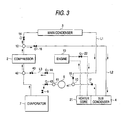
- Fig. 1 shows schematically the structure of an embodiment of an air conditioner for a vehicle according to the invention.
- the air conditioner for a vehicle shown in Fig. 1 comprises a refrigeration cycle for circulating a refrigerant and a hot water line for circulating engine cooling water.
- a compressor 2 In the refrigeration cycle, a compressor 2, a main condenser 3 serving as an outside-vehicle-compartment heat exchanger, a sub-condenser 4 serving as a heat radiating within-vehicle-compartment heat exchanger, a liquid tank 5, an expansion valve 6 serving as an expander, and an evaporator 7 serving as a heat absorbing within-vehicle-compartment heat exchanger are connected to one another through pipe members; and, a refrigerant, when energy is given thereto by the compressor 2, is allowed to circulate between the above respective components.
- the compressor 2 which is disposed outside a vehicle compartment such as an engine room, compresses a vapor-phase refrigerant having a low pressure absorbed therein and jets out the compressed refrigerant therefrom as a vapor-phase refrigerant having a high pressure.
- the compressor 2 can be driven, for example, by transmitting the power of a crankshaft of an engine 10 to the compressor 2 through a belt.
- the compressor 2 preferably, there may be used a variable-capacity compressor the refrigerant discharge amount of which can be controlled.
- a variable-capacity compressor the cooling and heating performance is controlled according to the refrigerant discharge amount and, therefore, while reducing the required power of the compressor 2, the temperature within the vehicle compartment can be adjusted efficiently.
- the main condenser 3 is used to radiate the heat of the high-temperature and high-pressure vapor-phase refrigerant jetted out from the compressor 2 to the outside.
- This main condenser 3 is disposed in such a manner that, when an air blower 11 such as an electric fan is driven, the air can be blown to the main condenser 3.
- the main condenser 3 exchanges heat between the high-temperature and high-pressure vapor-phase refrigerant passing within the main condenser 3 and the air blown to the main condenser 3 to thereby radiate the heat of the high-temperature and high-pressure vapor-phase refrigerant to the air.
- the sub-condenser 4 is disposed in a within-vehicle-compartment air passage P1 (which will be discussed later) and is used to radiate the heat of the high-temperature and high-pressure vapor-phase refrigerant jetted out from the compressor 2 to the air flowing in the within-vehicle-compartment air passage P1.
- the air flowing in the within-vehicle-compartment air passage P1 absorbs the heat of the refrigerant radiated by the sub-condenser 4 and thus turns into the warm air, so that the warm air flows to the downstream side of the within-vehicle-compartment air passage P1.
- the sub-condenser 4 and main condenser 3 are connected together in parallel, which makes it possible to selectively use the sub-condenser 4 and main condenser 3. That is, a passage for the refrigerant jetted out from the compressor 2 branches through a three-way connector 12 into a first refrigerant line L1 which passes through the main condenser 3, and a second refrigerant line L2 passing through the sub-condenser 4. And, in the front stage of the liquid tank 5, the first and second refrigerant lines L1 and L2 join together through another three-way connector 13.
- the first refrigerant line L1 or second refrigerant line L2 can be selected.
- the electromagnetic valve 14 disposed in the first refrigerant line L1 is set in the "open” state, whereas the electromagnetic valve 16 disposed in the second refrigerant line L2 is set in the "closed” state.
- the first refrigerant line L1 is selected, so that the refrigerant jetted out from the compressor 2 is supplied to the main condenser 3.
- the electromagnetic valve 14 disposed in the first refrigerant line L1 is set in the "closed” state
- the electromagnetic valve 16 disposed in the second refrigerant line L2 is set in the "open” state.
- the second refrigerant line L2 is selected, so that the refrigerant jetted out from the compressor 2 is supplied to the sub-condenser 3.
- the control unit functions as a switch which is capable of selectively switching the first and second refrigerant lines L1 and L2; that is, the passage of the refrigerant jetted out from the compressor 2 can be switched between the cooling and heating operations by the control unit, so that the main condenser 3 and sub-condenser 4 can be used selectively.
- the liquid tank 5 is used to hold therein temporarily a liquid-phase refrigerant which is obtained when the heat of the refrigerant is radiated by the main condenser 3 or sub-condenser 4 and the refrigerant is thereby liquefied.
- This liquid tank 5 includes a dust-proof filter and thus has a function to remove dust mixed into the liquid-phase refrigerant held therein.
- the liquid tank 5 may be disposed in the rear stage of the three-way connector 13. However, when it is difficult to dispose the liquid tank 5 in the rear stage of the three-way connector 13 due to the limit of the pipe lay-out arrangement within the engine room, as shown by a one-dot chained line in Fig.
- the liquid tank 5 may be disposed just behind the main condenser 3 or may be disposed so as to be integral with the main condenser 3.
- the liquid-phase refrigerant which is liquefied due to the radiation of the heat from the refrigerant by the sub-condenser 4 is supplied directly to the expansion valve 6 not through the liquid tank 5.
- the expansion valve 6 expands suddenly the liquid-phase refrigerant, which is obtained when the heat of the refrigerant is radiated by the main condenser 3 or sub-condenser 4 and is then held in the liquid tank 5 temporarily, to thereby be able to supply the liquid-phase refrigerant to the evaporator 7 in the form of a mist-like refrigerant of low temperature and high pressure.
- the evaporator 7 is disposed upstream of the sub-condenser 4 in the within-vehicle-compartment air passage P1 and allows the heat of the air flowing through the within-vehicle-compartment air passage P1 to be absorbed by the mist-like refrigerant of low temperature and high pressure supplied from the expansion valve 6.
- the refrigerant supplied to the evaporator 7 as the mist-like refrigerant of low temperature and high pressure when passing through the evaporator 7, absorbs the heat of the air flowing through the within-vehicle-compartment air passage P1 and is thereby vaporized. And, the vapor-phase refrigerant is sucked into the compressor 2, is compressed again and is jetted out from the compressor 2.
- the refrigeration cycle allows the refrigerant to circulate in the above-mentioned manner and carries out heat exchange in the main condenser 3 or sub-condenser 4 and in the evaporator 7, thereby generating the warm air or cold air in the within-vehicle-compartment air passage P1.
- the hot water line carries out heat by allowing the engine cooling water to circulate, that is, by using the engine cooling water the temperature of which has been raised up to a high temperature due to the waste heat of the engine 10; and, a heater core 21 serving as a heat generator is incorporated into the hot water line.
- the heater core 21, together with the sub-condenser 4, is disposed downstream of the evaporator 7 in the within-vehicle-compartment air passage P1; and, using, as its heat medium, the engine cooling water to be supplied through a pipe member from the water jacket of the engine 10, that is, the engine cooling water the temperature of which has been raised up to a high temperature due to the waste heat of the engine 10, the heater core 21 generates heat due to the heat of the high-temperature engine cooling water.
- the air flowing in the within-vehicle-compartment air passage P1 absorbs not only the heat of the refrigerant the heat of which is radiated by the above-mentioned sub-condenser 4 but also the heat given from the heater core 21.
- the warm air can be produced effectively in the within-vehicle-compartment air passage P1.
- a water valve 22 in the pipe member for supplying the engine cooling water from the water jacket of the engine 10 to the heater core 21, there is disposed a water valve 22; and, the water valve 22 can be adjusted under the control of the above-mentioned control unit, whereby the flow rate of the engine cooling water to be supplied to the heater core 21, that is, the heating value of the heater core 21 can be adjusted.
- the sub-condenser 4 which is a heat radiating within-vehicle-compartment heat exchanger, is disposed at a position where it is able to receive the heat from the heater core 21 serving as a heat generator.
- the position permitting reception of the heat from the heater core 21 means a position to which the heat from the heater core 21 can be transmitted.
- the sub-condenser 4 is able to receive the heat from the heater core 21.
- the sub-condenser 4 serving as a heat radiating within-vehicle-compartment heat exchanger is disposed at a position where it is able to receive the heat from the heater core 21 serving as a heat generator, as will be discussed later in detail, by increasing the temperature load of the sub-condenser 4, the refrigerant discharge pressure (Pd) can be increased quickly, which makes it possible to fulfill its quick heating performance very excellently.
- the heater core 21 serving as a heat generator may be disposed upstream of the sub-condenser 4 which serves as a heat radiating within-vehicle-compartment heat exchanger in the within-vehicle-compartment air passage P1.
- the air which is introduced into the within-vehicle-compartment air passage P1 and is passed through the evaporator 7 to be thereby turn into the cold air, is contacted directly with the sub-condenser 4 to thereby decrease the temperature load of the sub-condenser 4 further, which makes it difficult to raise the refrigerant discharge pressure.
- the heater core 21 is disposed upstream of the sub-condenser 4, the air, which has been turned into the cold air by the evaporator 7, is contacted through the heater core 21 with the sub-condenser 4 and, therefore, the temperature load of the sub-condenser 4 is not decreased so much, which makes it possible to raise the refrigerant discharge pressure further quickly. Also, in this case, since the heat of the heater core 21 can also be transmitted to the sub-condenser 4 through the air flowing in the within-vehicle-compartment air passage P1, the transmission efficiency of the heat to be transmitted from the heater core 21 to the sub-condenser 4 can enhanced, which makes it possible to fulfill the quick heating performance more excellently.
- the sub-condenser 4 serving as a heat radiating within-vehicle-compartment heat exchanger and the heater core 21 serving as a heat generator may be formed as an integral body.
- the sub-condenser 4 and heater core 21 are formed as an integral body, since the heat from the heater core 21 is transmitted directly to the sub-condenser 4, the transmission efficiency of the heat to be transmitted from the heater core 21 to the sub-condenser 4 can enhanced, which makes it possible to fulfill the quick heating performance quite excellently.
- the sub-condenser 4 and heater core 21 are formed as an integral body, there can be provided a great advantage in reducing the size of the whole vehicle air conditioner as well as the manufacturing cost thereof.
- the fins of the sub-condenser 4 may be formed integral with the fins of the heater core 21.
- a blower fan 31 On the upstream side of the within-vehicle-compartment air passage P1, there is disposed a blower fan 31.
- the outside air is introduced into the within-vehicle-compartment air passage P1 from an outside air introduction port, or the inside air is introduced into the within-vehicle-compartment air passage P1 from an inside air introduction port, the outside air or inside air is allowed to flow through the within-vehicle-compartment air passage P1.
- the air (outside air or inside air) introduced into the within-vehicle-compartment air passage P1 from the outside or inside air introduction port firstly, passes through the evaporator 7 disposed on the upstream side of the within-vehicle-compartment air passage P1.
- the heat of the air passing through the evaporator 7 is absorbed by the refrigerant existing in the evaporator 7, that is, the air is dehumidified and is thereby turned into the cold air, so that the cold air flows to the downstream side of the within-vehicle-compartment air passage P1.
- the downstream side of the evaporator 7 branches into a warm air passage, in which the heater core 21 and sub-condenser 4 are disposed, and a detour passage bypassing the heater core 21 and sub-condenser 4.
- the air which is introduced into the warm air passage, as described above, when passing through the heater core 21, absorbs the heat from the heater core 21 and, when passing through the sub-condenser 4, absorbs the heat radiated from the refrigerant existing within the sub-condenser 4 to thereby turn into the warm air, so that the warm air flows to the downstream side.
- the air, which is introduced into the detour passage flows to the downstream side as it remains the cold air the heat of which has been absorbed into the evaporator 7.
- an air mix door 33 which is used to adjust the ratio of the flow rate of the air to be introduced into the warm air passage and the flow rate of the air to be introduced into the detour passage.
- the air mix door 33 is driven under the control of the control unit to adjust the ratio of the flow rate of the air to be introduced into the warm air passage and the flow rate of the air to be introduced into the detour passage, finally, the temperatures of the air to be blown out from a defroster blow-out port, a vent blow-out port and a foot blow-out port can be adjusted.
- an air mix chamber 34 which is used to mix the warm air from the warm air passage with the cold air from the detour passage.
- a defroster blow-out port used to blow out the air, which is a mixture of the warm air and cold air and thus the temperature of which has been adjusted due to the mixing thereof, to a front windshield, a vent blow-out port for blowing out the air toward the upper body of an occupant, and a foot blow-out port for blowing out the air toward the foot of the occupant.
- vent blow-out port and foot blow-out port there are disposed a defrost door 35, a vent door 36, and a foot door 37, respectively.
- the defrost door 35, vent door 36 and foot door 37 are respectively driven under the control of the control unit, the flow rate of the temperature-controlled air to be blown out from the blow-out port, vent blow-out port and foot blow-out port can be adjusted.
- the heater core 21 serving as a heat generator but also the sub-condenser 4 serving as a heat radiating within-vehicle-compartment heat exchanger are disposed in the within-vehicle-compartment air passage P1 and thus, using not only the heater core 21 but also the sub-condenser 4, the warm air can be produced. Thanks to this, even in case where the temperature of the engine cooling water is not sufficiently high, there can be obtained an excellent heating performance.
- the sub-condenser 4 serving as a heat radiating within-vehicle-compartment heat exchanger is disposed at a position which permits reception of the heat from the heater core 21 serving as a heat generator, the heat from the heater core 21 can be effectively transmitted to the sub-condenser. Due to this, the temperature load of the sub-condenser 4 can be increased and thus the refrigerant discharge pressure (Pd) can be raised quickly, thereby being able to raise the temperature within the vehicle compartment; that is, the present vehicle air conditioner 1 is able to fulfill a very excellent quick heating performance.
- the temperature of the sub-condenser 4 is very low, that is, the temperature load of the sub-condenser 4 is low and thus the refrigerant discharge pressure is low.
- the refrigerant discharge pressure is low in this manner, it is not possible to function the sub-condenser 4 instantaneously as a heating source for generating the warm air to thereby produce the warm air quickly. Therefore, it is desired that heat from a heating source such as the heater core 21 is transmitted to the sub-condenser 4 to thereby increase the temperature load of the sub-condenser 4.
- the heat of the heater core 21 cannot be transmitted to the sub-condenser 4 effectively.
- the air is rather cooled against expectation and makes an occupant feel uncomfortable; and, therefore, the air is prevented from flowing into the within-vehicle-compartment air passage P1.
- the heat of the heater core 21 cannot be transmitted to the sub-condenser 4 effectively. Due to this, the temperature load of the sub-condenser 4 remains low. In this case, a state, in which the refrigerant discharge pressure is difficult to rise, continues for a given period of time, which makes is difficult to raise the temperature within the vehicle compartment quickly.
- the sub-condenser 4 is disposed at a position permitting reception of the heat from the heater core 21, even in case where the air does not flow in the within-vehicle-compartment air passage P1, the heat from the heater core 21 can be effectively transmitted to the sub-condenser 4. Therefore, in the vehicle air conditioner 1 according to the invention, just after the start thereof, the temperature load of the sub-condenser 4 can be effectively increased and thus the refrigerant discharge pressure can be raised quickly, which enables the vehicle air conditioner 1 according to the invention to fulfill a very excellent quick heating performance.
- the temperature load of the sub-condenser 4 can be effectively increased and thus the refrigerant discharge pressure can be raised quickly, so that the enclosure amount of the refrigerant in the refrigeration cycle can be reduced. Therefore, it is not necessary to use a large-sized liquid tank 5, which provides a very great advantage in reducing the size and weight of the whole vehicle air conditioner 1. Also, because the refrigerant discharge pressure canbe raised quickly, even in case where a variable-capacity compressor is used as the compressor 2, the amount of the refrigerant stored in a crank room can be reduced to thereby be able to enhance the response property of the variable-capacity compressor.
- the sub-condenser 4 and main condenser 3 are connected in parallel and thus the sub-condenser 4 and main condenser 3 can be used selectively. Therefore, in case where, in the cooling operation time, the refrigerant jetted out from the compressor 2 is supplied only to the main condenser 3 and, in the heating operation time, the refrigerant jetted out from the compressor 2 is supplied only to the sub-condenser 4, not only the above-mentioned heating performance can be enhanced but also the cooling efficiency in the cooling operation time can be enhanced.
- the sub-condenser 4 is disposed at a position permitting reception of the heat from the heater core 21, in case where the refrigerant, which is over-cooled because it has passed through the main condenser 3 in the cooling operation time, is supplied to the sub-condenser 4, it is difficult to maintain the refrigerant in the over-cooled condition, which raises a high possibility that the cooling efficiency can be lowered.
- the evaporator 7 can be overcooled by the outside air to thereby suddenly lower the heat conversion efficiency of the evaporator 7, which makes it difficult to keep the refrigerant pressure at a proper level, resulting in the lowered in the cooling and heating efficiency.
- the temperature of the evaporator 7 is controlled in the following manner: that is, the degree of opening of the intake door 32 is finely controlled by the control unit to thereby adjust the switch-over of the introduction of the inside air and outside air with high accuracy.
- a passage for the refrigerant jetted out from the compressor 2 branches through the three-way connector 12 into a first refrigerant line L1 in which the refrigerant is guided through the main condenser 3 to the evaporator 7, and a third refrigerant line L3 in which the refrigerant passes through the main condenser 3 but bypasses the evaporator 7. And, in the rear stage of the evaporator 7, these first and third refrigerant lines L1 and L3 join together through the three-way connector 13.
- the first refrigerant line L1 there is disposed an electromagnetic valve 14 in the front stage of the main condenser 3 and, in the rear stage of the evaporator 7, there is disposed a check valve 15.
- the third refrigerant line L3 there is disposed an electromagnetic valve 16 in the front stage of the main condenser 3 and, in the rear stage of the sub-condenser 4, there is disposed a pressure reducing valve 40 serving as an expander which is not connected to the evaporator 7. And, in case where the open.
- the first refrigerant line L1 or third refrigerant line L3 can be selected.
- the control unit sets the electromagnetic valve 14 disposed in the first refrigerant line L1 in the "open” state, and sets the electromagnetic valve 40 disposed in the third refrigerant line L3 in the "closed” state.
- the first refrigerant line L1 is selected; and, the refrigerant jetted out from the compressor 2 is supplied sequentially to the main condenser 3, liquid tank 5, expansion valve 6 and evaporator 7 in this order, and is finally sucked into the compressor 2 again.
- the control unit sets the electromagnetic valve 14 disposed in the first refrigerant line L1 in the "closed” state, and sets the electromagnetic valve 40 disposed in the third refrigerant line L3 in the "open” state.
- the third refrigerant line L3 is selected; and, the refrigerant jetted out from the compressor 2 is supplied to the sub-condenser 3 and pressure reducing valve 40, bypasses the evaporator 7 and is finally sucked into the compressor 2 again.
- a passage for the refrigerant jetted out from the compressor 2 branches through the three-way connector 12 into a first refrigerant line L1 in which the refrigerant passes through main condenser 3, and a second refrigerant line L2 in which the refrigerant passes through the sub-condenser 4. And, in the front stage of the liquid tank 5, these first and second refrigerant lines L1 and L2 join together through the three-way connector 13.
- the refrigerant flow passage which joined in the front stage of the liquid tank 5, further branches, through the three-way connector 41 disposed in the rear stage of the liquid tank 5, into a refrigerant line (the first refrigerant line L1 or second refrigerant line L2) in which the refrigerant passes through the evaporator 7, and a third refrigerant line L3 in which the refrigerant bypasses the evaporator 7.
- the first refrigerant line L1 or second refrigerant line L2 and the third refrigerant line L3 joins together through a three-way connector 42 in the front stage of the compressor 2.
- first refrigerant line L1 there is disposed an electromagnetic valve 14 in the front stage of the main condenser 3; and, in the rear stage of the main condenser 3, there is disposed a check valve 15.
- second refrigerant line L2 there is disposed an electromagnetic valve 16 in the front stage of the sub-condenser 4; and, in the rear stage of the sub-condenser 4, there is disposed a check valve 17.
- an electromagnetic valve 43 in the front stage of the expansion valve 6 of the first refrigerant line L1 or second refrigerant line L2, there is disposed an electromagnetic valve 43.
- the third refrigerant line L3 there is disposed a pressure reducing valve 40 serving as an expander which is not connected to the evaporator 7; and, in the front stage of the pressure reducing valve 40, there is disposed an electromagnetic valve 44. And, in case where the open and closed states of the respective electromagnetic valves 14, 16, 43, 44 are switched by the control unit, the first refrigerant line L1, or second refrigerant line L2, or third refrigerant line L3 can be selected.
- the control unit sets the electromagnetic valves 14 and 43 respectively in the “open” states, and sets the electromagnetic valves 16 and 44 respectively in the "closed” states.
- the first refrigerant line L1 is selected, and the refrigerant jetted out from the compressor 2 is supplied to the main condenser 3, liquid tank 5, expansion valve 6 and evaporator 7 in this order and is finally sucked into the compressor 2 again.
- the control unit sets the electromagnetic valves 14 and 43 respectively in the "closed” states, and sets the electromagnetic valves 16 and 44 respectively in the "open” states.
- the third refrigerant line L3 is selected, and the refrigerant jetted out from the compressor 2 is supplied to the sub-condenser 4, liquid tank 5 and pressure reducing valve 40 in this order, bypasses the evaporator 7 and is then returned into the compressor 2 again.
- the control unit is structured such that, in the heating operation time, it sets the electromagnetic valves 14 and 44 respectively in the "closed” states and sets the electromagnetic valves 16 and 43 respectively in the "open” states, the second refrigerant line L2 is selected, and the refrigerant jetted out from the compressor 2 is supplied to the sub-condenser 4, liquid tank 5, expansion valve 6 and evaporator 7 in this order, and is then sucked into the compressor 2 again.
- the heat of the refrigerant is radiated by the sub-condenser 4 and the refrigerant is then expanded by the pressure reducing valve 40, so that the temperature of the refrigerant becomes low; that is, the refrigerant of low temperature is sucked into the compressor 2 without the heat of the refrigerant being absorbed by the evaporator 7. Therefore, in the heating operation time, the temperature of the refrigerant jetted out from the compressor 2 is apt to be low, which raises a fear that the low-temperature refrigerent can provide an obstacle in the way of sufficient fulfillment of the quick heating performance.
- the third refrigerant line L3 there may be disposed an inter-refrigerant heat exchanger 45 which is used to exchange heat between the refrigerant expanded by the pressure reducing valve 40 and the refrigerant flowing in the front stage of the sub-condenser 4.
- an inter-refrigerant heat exchanger 45 which is used to exchange heat between the refrigerant expanded by the pressure reducing valve 40 and the refrigerant flowing in the front stage of the pressure reducing valve 40.
- inter-refrigerant heat exchanger 45 for example, as shown in Figs. 6 and 7, there can be used an integral type of pipe member structured such that a pipe member in the rear stage of the pressure reducing valve 40 and a pipe member in the front stage of the sub-condenser 4 or a pipe member in the front stage of the pressure reducing valve 40 are formed as an integral body; or, as shown in Fig. 8, a composite type of pipe member structured such that a pipe member in the rear stage of the pressure reducing valve 40 and a pipe member in the front stage of the sub-condenser 4 or a pipe member in the front stage of the pressure reducing valve 40 are closely contacted with each other.
- the inter-refrigerant heat exchanger 45 is disposed in the third refrigerant line L3 and the refrigerant expanded by the pressure reducing valve 40 is heated due to the heat exchange operation to be executed by the inter-refrigerant heat exchanger 45, even when the refrigerant is made to bypass the evaporator 7, the temperature of the refrigerant jetted out from the compressor 2 can be raised to thereby be able to obtain an excellent quick heating performance.
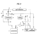
- the sub-condenser 4 and main condenser 3 are connected in parallel, while the main condenser 3 is used only in the cooling operation time but is not used in the heating operation time. Therefore, in order to enhance the use efficiency of the main condenser 3, as shown in Fig. 9, preferably, there may be disposed a refrigerant collecting line L4 which is used to connect the refrigerant sucking side of the compressor 2 with the main condenser 3 and, when the vehicle air conditioner 1 is switched from the cooling operation to the heating operation, using the refrigerant collecting line L4, the refrigerant staying in the main condenser 3 may be collected and sucked into the compressor 2.
- a refrigerant collecting line L4 which is used to connect the refrigerant sucking side of the compressor 2 with the main condenser 3 and, when the vehicle air conditioner 1 is switched from the cooling operation to the heating operation, using the refrigerant collecting line L4, the refrigerant staying in the main condenser 3 may be collected and sucked
- the temperature load of the sub-condenser 4 can be increased and thus the refrigerant discharge pressure can be increased. Therefore, when a sufficient quantity of refrigerant can be secured even in case where the refrigerant staying in the main condenser 3 is not collected, the above-mentioned refrigerant collecting line L4 may not be disposed. In case where the refrigerant collecting line L4 is not disposed, the size and weight of the whole of the vehicle air conditioner 1 can be reduced accordingly.
- the three-way connector 13 may be disposed in the front stage of the sub-condenser 4 to thereby connect the sub-condenser 4 and main condenser 3 in series with each other, and thus, in the cooling operation time, the refrigerant, which has passed through the main condenser 3, may be supplied to the sub-condenser 4.
- the invention is not limited to the specific embodiment but the invention can also be widely applied to an air conditioner for a vehicle in which, in the within-vehicle-compartment air passage P1, there are disposed at least a within-vehicle-compartment heat exchanger serving as a heat radiator in the heating operation and a heat generator.
- the invention can also be effectively applied to, for example, a vehicle air conditioner of a so-called hot gas cycle disclosed in JP-A-5-223357 and a vehicle air conditioner of a so-called heat pump cycle disclosed in JP-A-2-290475.
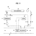
- Fig. 11 shows an embodiment of the structure of a vehicle air conditioner of a hot gas cycle to which the invention is applied.
- a passage for a refrigerant jetted out from a compressor 51 branches through a three-way connector 52 into a refrigerant line in which the refrigerant passes through a condenser 53 serving as an outside-vehicle-compartment heat exchanger, and a refrigerant line in which the refrigerant bypasses the condenser 53.
- a heater core 57 serving as a heat generator which exchanges heat using the cooling water of an engine 56.
- the evaporator 54 is disposed at a position which permits reception of the heat from the heater core 57.
- an electromagnetic valve 58 in the front stage of the condenser 53 and there are disposed a liquid tank 59, a check valve 60 and first an expander 61 respectively in the rear stage of the condenser 53.
- an electromagnetic valve 62 in the refrigerant line in which the refrigerant bypasses the condenser 53, there are disposed an electromagnetic valve 62 and an expander 63.
- an accumulator 64 in the passage of the refrigerant passing through the evaporator 54 and flowing toward the compressor 51, there is disposed an accumulator 64.
- the refrigerant line passing through the condenser 53 or the refrigerant line bypassing the condenser 53 can be selected.
- the control unit sets the electromagnetic valve 58 in the "open” state and sets the electromagnetic valve 62 in the "closed” state.
- the refrigerant line passing through the condenser 53 is selected and the refrigerant jetted out from the compressor 51 is supplied to the condenser 53, liquid tank 59, first an expander 61, evaporator 54 and accumulator 64 in this order, and is then sucked into the compressor 51 again.
- the evaporator 54 functions as a heat absorber, thereby allowing the cold air to flow into the within-vehicle-compartment air passage P1.
- the control unit sets the electromagnetic valve 58 in the "closed” state and sets the electromagnetic valve 62 in the "open” state.
- the refrigerant line bypassing the condenser 53 is selected and the refrigerant jetted out from the compressor 51 is supplied to the second expander 63, evaporator 54 and accumulator 64 in this order, and is then sucked into the compressor 51 again.
- the evaporator 54 functions as a heat radiator, thereby allowing the warm air to flow into the within-vehicle-compartment air passage P1.
- the evaporator 54 serving as a within-vehicle-compartment heat exchanger is disposed at a position which permits reception of the heat from the heater core 57 serving as a heat generator, even in a state where the air does not flow through the within-vehicle-compartment air passage P1, the heat from the heater core 57 can be effectively transmitted to the evaporator 54. Therefore, in the vehicle air conditioner 50, just after it is started, the temperature load of the evaporator 54 can be increased effectively and thus the refrigerant discharge pressure can be raised rapidly, so that, similarly to the previously described vehicle air conditioner 1, a very excellent quick heating performance can be fulfilled.
- the heat of the heater core 57 can also be transmitted to the evaporator 54 through the air flowing through the within-vehicle-compartment air passage P1
- the transmission efficiency of the heat to be transmitted from the heater core 57 to the evaporator 54 can be enhanced, which makes it possible to fulfill the quick heating performance still further.
- the heat from the heater core 57 is transmitted directly to the evaporator 54. Thanks to this, the transmission efficiency of the heat to be transmitted from the heater core 57 to the evaporator 54 can be enhanced still further, thereby being able to fulfill a very excellent quick heating performance.
- the temperature load of the evaporator 54 can be increased effectively and thus the refrigerant discharge pressure can be raised rapidly, thereby being able to reduce the quantity of the refrigerant to be enclosed within the refrigeration cycle. Thanks to this, similarly to the previously described vehicle air conditioner 1, there can be provided a great advantage in reducing the size and weight of the whole of the vehicle air conditioner.
- Fig. 12 shows an embodiment of the structure of a vehicle air conditioner of a heat pump cycle according to the invention.
- a passage for a refrigerant jetted out from a compressor 71 can be reversed by a four-way valve 72; and, therefore, the supply order of the refrigerant to be supplied to a condenser 73 serving as an outside-vehicle-compartment heat exchanger and to an evaporator 74 disposed in a within-vehicle-compartment air passage P1 and serving as a within-vehicle-compartment heat exchanger can be switched.
- the vehicle air conditioner 70 in the within-vehicle-compartment air passage P1, in addition to the evaporator 70, there is disposed a heater core 76 which serves as a heat generator for exchanging heat using the cooling water of an engine 75. And, the evaporator 74 is disposed at a position which permits reception of the heat from the heater core 76.
- a refrigerant passage between the condenser 73 and evaporator 74 there is disposed first an expander 77 in the vicinity of the condenser 73, while there is disposed a second expander 78 in the vicinity of the evaporator 74.
- a detour line in which the refrigerant bypasses the first an expander 77 through three-way connectors 79, 80 respectively provided before and behind the first an expander 77; and, in the detour line, there is disposed an electromagnetic valve 81.
- detour line in which the refrigerant bypasses the second expander 78 through three-way connectors 82, 83 respectively provided before and behind the second expander 78; and, in this detour line, there is disposed an electromagnetic valve 84. Also, on the refrigerant suction side of the compressor 71, there is disposed an accumulator 85.
- the passage (the forward-direction passage or the reversed-direction passage) of the refrigerant jetted out from the compressor 71 as well as the first an expander 77 or a second expander 78 can be selected.
- the control unit sets the direction of the refrigerant passing through the four-way connector 72 in a direction shown by a solid line in Fig. 12, sets the electromagnetic valve 81 in the "open” state, and sets the electromagnetic valve 84 in the "closed” state.
- the refrigerant jetted out from the compressor 71 is supplied to the condenser 73, a second expander 78, evaporator 74 and accumulator 85 in this order and is then sucked into the compressor 71 again.
- the condenser 73 functions as a heat radiator and the evaporator 74 functions as a heat absorber, so that the cold air is allowed to flow through the within-vehicle-compartment air passage P1.
- the control unit sets the direction of the refrigerant passing through the four-way connector 72 in a direction shown by a broken line in Fig. 12, sets the electromagnetic valve 81 in the "closed” state, and sets the electromagnetic valve 84 in the "open” state.
- the refrigerant jetted out from the compressor 71 is supplied to the evaporator 74, first an expander 77, condenser 73 and accumulator 85 in this order and is then sucked into the compressor 71 again.
- the evaporator 74 functions as a heat radiator and the condenser 73 functions as a heat absorber, so that the warm air is allowed to flow through the within-vehicle-compartment air passage P1.
- the evaporator 74 serving as an within-vehicle-compartment heat exchanger is disposed at a position which permits reception of the heat from the heater core 76 serving as a heat generator, even in case where the air does not flow through the within-vehicle-compartment air passage P1, the heat from the heater core 76 can be transmitted to the evaporator 74 effectively.
- the present vehicle air conditioner 70 just after it is started, the temperature load of the evaporator 74 can be increased effectively and thus the refrigerant discharge pressure can be raised rapidly, so that, similarly to the previously described vehicle air conditioners 1 and 50, the present vehicle air conditioner 70 is able to fulfill a very excellent quick heating performance.
- the heater core 76 serving as a heat generator is disposed upstream of the evaporator 74 which is a within-vehicle-compartment heat exchanger in the within-vehicle-compartment air passage P1
- the evaporator 74 which is a within-vehicle-compartment heat exchanger in the within-vehicle-compartment air passage P1
- the temperature load of the evaporator 74 is not lowered so much, thereby being able to raise the refrigerant discharge pressure rapidly.
- the heat of the heater core 76 can also be transmitted to the evaporator 74 through the air flowing in the within-vehicle-compartment air passage P1
- the transmission efficiency of the heat to be transmitted from the heater core 76 to the evaporator 74 can be enhanced, which enables the present vehicle air conditioner 70 to fulfill a further excellent quick heating performance.
- the evaporator 74 serving as a within-vehicle-compartment heat exchanger and heater core 76 serving as a heat generator are formed as an integral body, since the heat from the heater core 76 can be transmitted directly to the evaporator 74, the transmission efficiency of the heat to be transmitted from the heater core 76 to the evaporator 74 can be enhanced still further, so that the present vehicle air conditioner 70 is able to fulfill an extremely excellent quick heating performance.
- the temperature load of the evaporator 74 can be increased effectively and thus the refrigerant discharge pressure can be raised rapidly, the quantity of the refrigerant to be enclosed in the refrigeration cycle can be reduced. Thanks to this, similarly to the previously described vehicle air conditioners 1 and 50, there can be provided a great advantage in reducing the size and weight of the whole of the vehicle air conditioner 70.
- a vehicle air conditioner according to the invention has been described heretofore by way of several specific embodiments thereof, the structures and specifications of the respective parts forming the vehicle air conditioner can also be changed properly according to the performance required and the kinds of vehicles on which the present vehicle air conditioner is carried.
- the heat generator there is disposed the heater core 21, 57, or 76 using the engine cooling water as a heat source; however, instead of the heater core 21, 57, or 76, there may be disposed other types of a heat generator such as a heat transfer heater.
Applications Claiming Priority (2)
| Application Number | Priority Date | Filing Date | Title |
|---|---|---|---|
| JP2001016009 | 2001-01-24 | ||
| JP2001016009A JP2002211234A (ja) | 2000-11-14 | 2001-01-24 | 車両用空調装置 |
Publications (3)
| Publication Number | Publication Date |
|---|---|
| EP1226990A1 true EP1226990A1 (fr) | 2002-07-31 |
| EP1226990B1 EP1226990B1 (fr) | 2006-03-22 |
| EP1226990B2 EP1226990B2 (fr) | 2009-08-12 |
Family
ID=18882463
Family Applications (1)
| Application Number | Title | Priority Date | Filing Date |
|---|---|---|---|
| EP02001710A Expired - Lifetime EP1226990B2 (fr) | 2001-01-24 | 2002-01-24 | Climatiseur pour véhicule |
Country Status (3)
| Country | Link |
|---|---|
| US (1) | US6715307B2 (fr) |
| EP (1) | EP1226990B2 (fr) |
| DE (1) | DE60209949T3 (fr) |
Cited By (7)
| Publication number | Priority date | Publication date | Assignee | Title |
|---|---|---|---|---|
| EP1512924A2 (fr) * | 2003-09-05 | 2005-03-09 | LG Electronics Inc. | Climatiseur contenant échangeur de chaleur et dispositif pour commuter le cycle de refroidissement |
| EP1504934A3 (fr) * | 2003-08-04 | 2005-11-16 | Calsonic Kansei Corporation | Appareil de climatisation de véhicule |
| EP1623857A1 (fr) * | 2004-08-04 | 2006-02-08 | Delphi Technologies, Inc. | Systèmes de chauffage, de ventilation, d'air conditionné |
| ES2258380A1 (es) * | 2003-04-15 | 2006-08-16 | Siemens Aktiengesellschaft | Instalacion de climatizacion para automoviles con refrigerante de co2. |
| FR2993960A1 (fr) * | 2012-07-30 | 2014-01-31 | Valeo Systemes Thermiques | Boucle de conditionnement thermique pour vehicule automobile et procede de pilotage associe |
| EP2743107A1 (fr) * | 2012-12-14 | 2014-06-18 | Valeo Systemes Thermiques | Circuit et procédé de conditionnement d'air, notamment pour véhicule automobile |
| FR3057211A1 (fr) * | 2016-10-12 | 2018-04-13 | Valeo Systemes Thermiques | Procede de regulation d'une boucle de chauffage, ventilation et/ou climatisation |
Families Citing this family (26)
| Publication number | Priority date | Publication date | Assignee | Title |
|---|---|---|---|---|
| DE60303056T2 (de) * | 2002-03-15 | 2006-07-20 | Calsonic Kansei Corp. | Fahrzeugklimaanlage |
| US6862892B1 (en) * | 2003-08-19 | 2005-03-08 | Visteon Global Technologies, Inc. | Heat pump and air conditioning system for a vehicle |
| US7165414B2 (en) * | 2004-03-15 | 2007-01-23 | J. W. Wright, Inc. | System for the dehumification of air |
| US7380586B2 (en) | 2004-05-10 | 2008-06-03 | Bsst Llc | Climate control system for hybrid vehicles using thermoelectric devices |
| US7743614B2 (en) | 2005-04-08 | 2010-06-29 | Bsst Llc | Thermoelectric-based heating and cooling system |
| US7779643B2 (en) * | 2005-07-13 | 2010-08-24 | Everett Simons | Refrigeration cycle dehumidifier |
| JP2007253886A (ja) * | 2006-03-24 | 2007-10-04 | Denso Corp | 車両用空調装置 |
| US20100155018A1 (en) | 2008-12-19 | 2010-06-24 | Lakhi Nandlal Goenka | Hvac system for a hybrid vehicle |
| US20080264080A1 (en) * | 2007-04-24 | 2008-10-30 | Hunter Manufacturing Co. | Environmental control unit for harsh conditions |
| CN104990301B (zh) | 2007-05-25 | 2019-04-16 | 詹思姆公司 | 分配式热电加热和冷却的系统和方法 |
| EP2315987A2 (fr) | 2008-06-03 | 2011-05-04 | Bsst Llc | Pompe à chaleur thermoélectrique |
| US9555686B2 (en) | 2008-10-23 | 2017-01-31 | Gentherm Incorporated | Temperature control systems with thermoelectric devices |
| US9447994B2 (en) | 2008-10-23 | 2016-09-20 | Gentherm Incorporated | Temperature control systems with thermoelectric devices |
| KR102218137B1 (ko) | 2009-05-18 | 2021-02-22 | 젠썸 인코포레이티드 | 열전기 가열 및 냉각 시스템 |
| EP2433192B2 (fr) | 2009-05-18 | 2020-08-26 | Gentherm Incorporated | Système de régulation de température avec dispositif thermoélectrique |
| JP5488237B2 (ja) * | 2010-06-16 | 2014-05-14 | 日産自動車株式会社 | 車両用空調装置 |
| JP5815284B2 (ja) * | 2011-05-20 | 2015-11-17 | 株式会社日本自動車部品総合研究所 | 冷却装置 |
| KR101991650B1 (ko) | 2011-07-11 | 2019-06-20 | 젠썸 인코포레이티드 | 전기 장치들의 열전 기반 열 관리 |
| DE102013106209B4 (de) * | 2012-09-20 | 2020-09-10 | Hanon Systems | Klimatisierungsvorrichtung eines Kraftfahrzeuges mit einer Wärmeübertrageranordnung zur Wärmeaufnahme |
| US9358856B2 (en) * | 2013-10-03 | 2016-06-07 | Ford Global Technologies, Llc | System off configuration for climate control system |
| CN104833129B (zh) * | 2014-02-06 | 2017-12-19 | 翰昂汽车零部件有限公司 | 用于车辆的热泵系统 |
| DE112015005666T5 (de) | 2014-12-19 | 2017-09-14 | Gentherm Incorporated | Thermische Konditionierungssysteme und -verfahren für Fahrzeugbereiche |
| DE102015112030A1 (de) * | 2015-07-23 | 2017-01-26 | Halla Visteon Climate Control Corporation | Modulares Klimatisierungssystem eines Kraftfahrzeugs |
| US10625566B2 (en) | 2015-10-14 | 2020-04-21 | Gentherm Incorporated | Systems and methods for controlling thermal conditioning of vehicle regions |
| KR20210013425A (ko) * | 2019-07-24 | 2021-02-04 | 현대자동차주식회사 | 차량용 공조시스템 |
| US20220305876A1 (en) * | 2021-03-24 | 2022-09-29 | Ford Global Technologies, Llc | Methods and systems for instant cabin heat for a vehicle |
Citations (6)
| Publication number | Priority date | Publication date | Assignee | Title |
|---|---|---|---|---|
| JPH09142134A (ja) * | 1995-11-20 | 1997-06-03 | Denso Corp | バス車両用空調装置 |
| JPH106738A (ja) * | 1996-06-24 | 1998-01-13 | Sanden Corp | 車両用空調装置 |
| EP0913281A1 (fr) * | 1997-10-30 | 1999-05-06 | Calsonic Corporation | Dispositif de climatisation de véhicule |
| EP0960756A1 (fr) * | 1998-05-28 | 1999-12-01 | Valeo Climatisation | Dispositif de climatisation de véhicule utilisant un fluide réfrigérant à l'état supercritique |
| WO2000020240A1 (fr) * | 1998-10-07 | 2000-04-13 | Llanelli Radiators Limited | Systeme de climatisation pour automobile |
| DE19921812A1 (de) * | 1999-05-11 | 2000-11-23 | Valeo Klimasysteme Gmbh | Heizsystemkomponenten |
Family Cites Families (12)
| Publication number | Priority date | Publication date | Assignee | Title |
|---|---|---|---|---|
| JPH02290475A (ja) | 1989-04-28 | 1990-11-30 | Nippondenso Co Ltd | ヒートポンプ式冷暖房装置 |
| JP3237187B2 (ja) | 1991-06-24 | 2001-12-10 | 株式会社デンソー | 空調装置 |
| JPH1044742A (ja) | 1995-10-19 | 1998-02-17 | Calsonic Corp | 自動車用空気調和装置 |
| JP3460422B2 (ja) | 1995-12-26 | 2003-10-27 | 日産自動車株式会社 | 車両用空調装置 |
| JPH1076841A (ja) * | 1996-09-06 | 1998-03-24 | Calsonic Corp | ヒートポンプ式自動車用空気調和装置 |
| US6312800B1 (en) * | 1997-02-10 | 2001-11-06 | Lintec Corporation | Pressure sensitive adhesive sheet for producing a chip |
| JP3847905B2 (ja) * | 1997-06-30 | 2006-11-22 | カルソニックカンセイ株式会社 | ヒートポンプ式自動車用空気調和装置 |
| JPH11115466A (ja) * | 1997-10-20 | 1999-04-27 | Zexel:Kk | 電気車両用空調装置 |
| DE19855309C2 (de) † | 1998-12-01 | 2002-05-23 | Daimler Chrysler Ag | Zusätzliche Heizeinrichtung für Fahrzeuge |
| JP2000289455A (ja) * | 1999-04-09 | 2000-10-17 | Bosch Automotive Systems Corp | 車両用空調装置 |
| JP4230080B2 (ja) * | 2000-02-18 | 2009-02-25 | リンテック株式会社 | ウエハ貼着用粘着シート |
| JP2002187425A (ja) * | 2000-12-18 | 2002-07-02 | Calsonic Kansei Corp | 車両用空気調和装置 |
-
2002
- 2002-01-22 US US10/051,006 patent/US6715307B2/en not_active Expired - Fee Related
- 2002-01-24 DE DE60209949T patent/DE60209949T3/de not_active Expired - Lifetime
- 2002-01-24 EP EP02001710A patent/EP1226990B2/fr not_active Expired - Lifetime
Patent Citations (6)
| Publication number | Priority date | Publication date | Assignee | Title |
|---|---|---|---|---|
| JPH09142134A (ja) * | 1995-11-20 | 1997-06-03 | Denso Corp | バス車両用空調装置 |
| JPH106738A (ja) * | 1996-06-24 | 1998-01-13 | Sanden Corp | 車両用空調装置 |
| EP0913281A1 (fr) * | 1997-10-30 | 1999-05-06 | Calsonic Corporation | Dispositif de climatisation de véhicule |
| EP0960756A1 (fr) * | 1998-05-28 | 1999-12-01 | Valeo Climatisation | Dispositif de climatisation de véhicule utilisant un fluide réfrigérant à l'état supercritique |
| WO2000020240A1 (fr) * | 1998-10-07 | 2000-04-13 | Llanelli Radiators Limited | Systeme de climatisation pour automobile |
| DE19921812A1 (de) * | 1999-05-11 | 2000-11-23 | Valeo Klimasysteme Gmbh | Heizsystemkomponenten |
Non-Patent Citations (2)
| Title |
|---|
| PATENT ABSTRACTS OF JAPAN vol. 1997, no. 10 31 October 1997 (1997-10-31) * |
| PATENT ABSTRACTS OF JAPAN vol. 1998, no. 05 30 April 1998 (1998-04-30) * |
Cited By (10)
| Publication number | Priority date | Publication date | Assignee | Title |
|---|---|---|---|---|
| ES2258380A1 (es) * | 2003-04-15 | 2006-08-16 | Siemens Aktiengesellschaft | Instalacion de climatizacion para automoviles con refrigerante de co2. |
| EP1504934A3 (fr) * | 2003-08-04 | 2005-11-16 | Calsonic Kansei Corporation | Appareil de climatisation de véhicule |
| EP1512924A2 (fr) * | 2003-09-05 | 2005-03-09 | LG Electronics Inc. | Climatiseur contenant échangeur de chaleur et dispositif pour commuter le cycle de refroidissement |
| EP1512924A3 (fr) * | 2003-09-05 | 2011-01-26 | LG Electronics, Inc. | Climatiseur contenant échangeur de chaleur et dispositif pour commuter le cycle de refroidissement |
| EP1623857A1 (fr) * | 2004-08-04 | 2006-02-08 | Delphi Technologies, Inc. | Systèmes de chauffage, de ventilation, d'air conditionné |
| FR2993960A1 (fr) * | 2012-07-30 | 2014-01-31 | Valeo Systemes Thermiques | Boucle de conditionnement thermique pour vehicule automobile et procede de pilotage associe |
| EP2743107A1 (fr) * | 2012-12-14 | 2014-06-18 | Valeo Systemes Thermiques | Circuit et procédé de conditionnement d'air, notamment pour véhicule automobile |
| FR2999689A1 (fr) * | 2012-12-14 | 2014-06-20 | Valeo Systemes Thermiques | Circuit et procede de conditionnement d'air, notamment pour vehicule automobile |
| FR3057211A1 (fr) * | 2016-10-12 | 2018-04-13 | Valeo Systemes Thermiques | Procede de regulation d'une boucle de chauffage, ventilation et/ou climatisation |
| WO2018069606A1 (fr) * | 2016-10-12 | 2018-04-19 | Valeo Systemes Thermiques | Procede de regulation d'une boucle de chauffage, ventilation et/ou climatisation |
Also Published As
| Publication number | Publication date |
|---|---|
| DE60209949D1 (de) | 2006-05-11 |
| EP1226990B1 (fr) | 2006-03-22 |
| EP1226990B2 (fr) | 2009-08-12 |
| DE60209949T2 (de) | 2006-08-17 |
| DE60209949T3 (de) | 2009-12-03 |
| US6715307B2 (en) | 2004-04-06 |
| US20020095943A1 (en) | 2002-07-25 |
Similar Documents
| Publication | Publication Date | Title |
|---|---|---|
| US6715307B2 (en) | Air conditioner for vehicle | |
| JP6634160B2 (ja) | 車両用ヒートポンプシステム | |
| JP5187786B2 (ja) | 車両用ヒートポンプシステム | |
| US10189331B2 (en) | Vehicle air conditioner | |
| CN111231773B (zh) | 车辆热管理系统及其控制方法、车辆 | |
| US6370903B1 (en) | Heat-pump type air conditioning and heating system for fuel cell vehicles | |
| CN110997369B (zh) | 制冷循环装置 | |
| JP6108322B2 (ja) | 車両用空調装置 | |
| KR101669826B1 (ko) | 차량용 히트 펌프 시스템 | |
| JP2007278624A (ja) | ヒートポンプサイクル | |
| JP6590321B2 (ja) | 車両用空調装置 | |
| CN113226814A (zh) | 车辆用空调装置 | |
| JP2021147044A (ja) | 車室の空気を空調して自動車の駆動部品を通じて熱伝達するためのシステム及びそのシステムの動作方法 | |
| JP2019104393A (ja) | 車両用暖房装置 | |
| JP2002211234A (ja) | 車両用空調装置 | |
| JP2002225545A (ja) | 車両用空調装置 | |
| JP2004106799A (ja) | 車両用空調装置 | |
| CN113453926A (zh) | 车用空调装置 | |
| KR102577144B1 (ko) | 자동차용 히트펌프 시스템 | |
| CN219838413U (zh) | 车辆及其热管理系统 | |
| CN217672056U (zh) | 一种燃料电池车用热泵空调系统 | |
| WO2023243367A1 (fr) | Dispositif de climatisation pour véhicule | |
| CN212604367U (zh) | 一种热泵用汽车空调箱 | |
| CN218519497U (zh) | 汽车热管理空调系统、电动汽车 | |
| JP2024040735A (ja) | 空気調和システム |
Legal Events
| Date | Code | Title | Description |
|---|---|---|---|
| PUAI | Public reference made under article 153(3) epc to a published international application that has entered the european phase |
Free format text: ORIGINAL CODE: 0009012 |
|
| AK | Designated contracting states |
Kind code of ref document: A1 Designated state(s): AT BE CH CY DE DK ES FI FR GB GR IE IT LI LU MC NL PT SE TR |
|
| AX | Request for extension of the european patent |
Free format text: AL;LT;LV;MK;RO;SI |
|
| 17P | Request for examination filed |
Effective date: 20021023 |
|
| 17Q | First examination report despatched |
Effective date: 20030124 |
|
| AKX | Designation fees paid |
Designated state(s): DE FR GB |
|
| GRAP | Despatch of communication of intention to grant a patent |
Free format text: ORIGINAL CODE: EPIDOSNIGR1 |
|
| GRAS | Grant fee paid |
Free format text: ORIGINAL CODE: EPIDOSNIGR3 |
|
| GRAA | (expected) grant |
Free format text: ORIGINAL CODE: 0009210 |
|
| AK | Designated contracting states |
Kind code of ref document: B1 Designated state(s): DE FR GB |
|
| REG | Reference to a national code |
Ref country code: GB Ref legal event code: FG4D |
|
| REF | Corresponds to: |
Ref document number: 60209949 Country of ref document: DE Date of ref document: 20060511 Kind code of ref document: P |
|
| ET | Fr: translation filed | ||
| PLBI | Opposition filed |
Free format text: ORIGINAL CODE: 0009260 |
|
| 26 | Opposition filed |
Opponent name: VISTEON GLOBAL TECHNOLOGIES, INC. Effective date: 20061220 |
|
| PLAX | Notice of opposition and request to file observation + time limit sent |
Free format text: ORIGINAL CODE: EPIDOSNOBS2 |
|
| PLAF | Information modified related to communication of a notice of opposition and request to file observations + time limit |
Free format text: ORIGINAL CODE: EPIDOSCOBS2 |
|
| PLAF | Information modified related to communication of a notice of opposition and request to file observations + time limit |
Free format text: ORIGINAL CODE: EPIDOSCOBS2 |
|
| PLBB | Reply of patent proprietor to notice(s) of opposition received |
Free format text: ORIGINAL CODE: EPIDOSNOBS3 |
|
| PUAH | Patent maintained in amended form |
Free format text: ORIGINAL CODE: 0009272 |
|
| STAA | Information on the status of an ep patent application or granted ep patent |
Free format text: STATUS: PATENT MAINTAINED AS AMENDED |
|
| 27A | Patent maintained in amended form |
Effective date: 20090812 |
|
| AK | Designated contracting states |
Kind code of ref document: B2 Designated state(s): DE FR GB |
|
| REG | Reference to a national code |
Ref country code: GB Ref legal event code: 746 Effective date: 20090924 |
|
| PGFP | Annual fee paid to national office [announced via postgrant information from national office to epo] |
Ref country code: FR Payment date: 20130204 Year of fee payment: 12 Ref country code: DE Payment date: 20130116 Year of fee payment: 12 Ref country code: GB Payment date: 20130123 Year of fee payment: 12 |
|
| REG | Reference to a national code |
Ref country code: DE Ref legal event code: R119 Ref document number: 60209949 Country of ref document: DE |
|
| GBPC | Gb: european patent ceased through non-payment of renewal fee |
Effective date: 20140124 |
|
| PG25 | Lapsed in a contracting state [announced via postgrant information from national office to epo] |
Ref country code: DE Free format text: LAPSE BECAUSE OF NON-PAYMENT OF DUE FEES Effective date: 20140801 |
|
| REG | Reference to a national code |
Ref country code: FR Ref legal event code: ST Effective date: 20140930 |
|
| REG | Reference to a national code |
Ref country code: DE Ref legal event code: R119 Ref document number: 60209949 Country of ref document: DE Effective date: 20140801 |
|
| PG25 | Lapsed in a contracting state [announced via postgrant information from national office to epo] |
Ref country code: GB Free format text: LAPSE BECAUSE OF NON-PAYMENT OF DUE FEES Effective date: 20140124 Ref country code: FR Free format text: LAPSE BECAUSE OF NON-PAYMENT OF DUE FEES Effective date: 20140131 |