EP1226062B1 - Rear axle arrangement for a heavy vehicle - Google Patents
Rear axle arrangement for a heavy vehicle Download PDFInfo
- Publication number
- EP1226062B1 EP1226062B1 EP00966664A EP00966664A EP1226062B1 EP 1226062 B1 EP1226062 B1 EP 1226062B1 EP 00966664 A EP00966664 A EP 00966664A EP 00966664 A EP00966664 A EP 00966664A EP 1226062 B1 EP1226062 B1 EP 1226062B1
- Authority
- EP
- European Patent Office
- Prior art keywords
- rear axle
- frame structure
- axle arrangement
- vehicle
- incorporates
- Prior art date
- Legal status (The legal status is an assumption and is not a legal conclusion. Google has not performed a legal analysis and makes no representation as to the accuracy of the status listed.)
- Expired - Lifetime
Links
Images


Classifications
-
- B—PERFORMING OPERATIONS; TRANSPORTING
- B62—LAND VEHICLES FOR TRAVELLING OTHERWISE THAN ON RAILS
- B62D—MOTOR VEHICLES; TRAILERS
- B62D21/00—Understructures, i.e. chassis frame on which a vehicle body may be mounted
- B62D21/12—Understructures, i.e. chassis frame on which a vehicle body may be mounted assembled from readily detachable parts
-
- B—PERFORMING OPERATIONS; TRANSPORTING
- B62—LAND VEHICLES FOR TRAVELLING OTHERWISE THAN ON RAILS
- B62D—MOTOR VEHICLES; TRAILERS
- B62D21/00—Understructures, i.e. chassis frame on which a vehicle body may be mounted
- B62D21/02—Understructures, i.e. chassis frame on which a vehicle body may be mounted comprising longitudinally or transversely arranged frame members
Definitions
- the present invention relates to a rear axle arrangement for a heavy vehicle according to the preamble to patent claim 1.
- Heavy vehicles which here means, for example, trucks, buses and similar freight and utility vehicles, incorporate according to conventional technology a longitudinal chassis element in the form of two frame side members which are connected to one another by means of a number of cross-members.
- the frame side members extend parallel with one another along substantially the whole length of the vehicle and support vehicle components such as the engine, the driver's cab and a load surface which takes the form, for example, of a load platform or a superstructure.
- the vehicle's front and rear axles are suspended in the frame side members.
- the frame side members and the cross-members act as main loadbearing parts of the vehicle in order to achieve strength and rigidity.
- the bodywork also contributes to vehicle rigidity and strength.
- Conventionally designed support devices are nevertheless built so as to be relatively unresistant to bending and torsion in order to be able to cope with heavy loads and varying road conditions, comprising a complete range from forest roads or no roads to smooth motorways.
- Relatively low resistance to bending and torsion does entail, however, certain problems with regard to riding comfort and vehicle running characteristics.
- the chassis element having relatively low resistance to torsion and the wheel axles being made of steel result in not entirely satisfactory riding comfort, particularly on long journeys and on good roads.
- the conventional superstructure of a heavy vehicle also has the disadvantage of its manufacture being relatively expensive because such a design involves many different components which cannot be standardised for different vehicle variants.
- the vehicle's front and rear axle arrangements may involve many different components depending on whether the respective wheels are to be steerable or not, powered or not, how many rear axles the vehicle is to have, the type of suspension, etc.
- Such a conventionally constructed heavy vehicle also requires a relatively large amount of assembly work.
- DE-A-4322716 describes a vehicle chassis for heavy-duty vehicles.
- the chassis incorporates a rear axle arrangement, a box-like central chassis element and a front axle arrangement.
- the rear and front axle arrangements are of conventional design in that they incorporate two longitudinal frame members which are connected to one another by means of cross-members.
- the wheel suspension seems to incorporate a steel wheel axle and the forces acting upon the wheels will be led on into the central tunnel-like chassis element.
- a rear axle arrangement according to the preamble of claim 1 is disclosed in EP-A-0 295 661.
- the object of the present invention is to provide a rear axle arrangement which constitutes a substantially self-supporting unit, i.e. which can absorb the forces acting upon the rear wheels and which contributes to better vehicle running characteristics.
- a further object of the present invention is to provide a rear axle arrangement which incorporates simple standardised components which are easy to fit and readily available, so that repair work and servicing operations can be performed easily and quickly.
- the rear axle arrangement incorporates at least one separate rear axle unit which itself incorporates a loadbearing frame structure and two of said wheels, said frame structure extends between a first end region and a second end region in said longitudinal direction and said first end region of said frame structure is designed to be connected to said elongate chassis element, and that said two wheels are suspended on said frame structure.
- the rear axle arrangement thus incorporates a separate unit which includes a frame structure, i.e. a framelike structure, on which two rear wheels are suspended.
- a frame structure i.e. a framelike structure
- the rear axle unit can easily be disassembled from the elongate chassis element and be replaced by another rear axle element, thus avoiding the vehicle being stationary in a workshop. Replacing one rear axle unit by another is a simple operation and need not take up valuable time.
- said rear axle unit forms a substantially self-supporting rear axle module, and any desired number, preferably two or three, of such rear axle modules may be connected to one another via said frame structures.
- the rear axle unit thus forms a self-supporting module.
- One rear axle arrangement can only incorporate one such module, but it is also possible to connect two or more such modules, in which case each module is self-supporting.
- said frame structure forms a space which extends through the frame structure in said longitudinal direction.
- the framelike structure thus exhibits a cavity which extends in the longitudinal direction of the vehicle.
- the frame structure incorporates two side portions which are situated at a distance from one another, extend in said longitudinal direction and are connected to one another by means of an upper portion and by means of at least one lower portion in such a way that said portions form said space between them.
- the result is a tunnel-like structure or may be likened to a boxlike structure which is open at both of its ends arranged in the longitudinal direction of the vehicle, extends in the longitudinal direction of the vehicle and is capable of absorbing at least substantially all the vertical forces which act upon the rear wheels.
- said portions as viewed in the longitudinal direction of the vehicle, form a substantially quadrilateral frame round said space.
- the result is a frame structure which has high rigidity and strength.
- each side portion has a lower section and an upper section, and each of the lower sections is of greater extent in said longitudinal direction than the respective upper section.
- said side portions may be connected to one another by two lower portions, in which case the first lower portion is arranged adjacent to the first end region of the frame structure and the second lower portion is arranged adjacent to the second end region of the frame structure. Said positioning of the lower portions results in a frame structure which has high rigidity and strength.
- each of said two wheels is suspended by means of a lower link arm and an upper link arm which are pivotingly connected to the frame structure.
- both the lower link arms and the upper link arms are pivotingly connected to respective said side portion.
- the rear axle unit also incorporates a spring device for each wheel, and each spring device is connected to the upper portion of the frame structure and a lower link arm.
- said wheels are powered and a differential gear is arranged in said frame structure.
- said differential gear is arranged in said space, in which case not only does each of said side portions incorporate an aperture but a respective driveshaft also extends from the respective wheel through said aperture to said differential gear.
- Said space extending through the frame structure in the longitudinal direction of the vehicle, i.e. the frame structure forming a hollow structure in the longitudinal direction of the vehicle, makes it easy for the differential gear to be arranged and fitted in said frame structure, either from the first end region of the frame structure or from the second end region of the frame structure, before the first end region of the rear axle unit is connected to the elongate chassis element of the vehicle.
- the differential gear is itself connected to the vehicle's engine via a gearbox and a driveshaft.
- the gearbox and driveshaft are situated in the vehicle's elongate chassis element in the vicinity of said frame structure.
- said rear axle unit incorporates a towbar which is directly connected to said frame structure.
- the towbar which is designed to make it possible to attach trailer vehicles to said vehicle, is thus directly connected to the rear axle unit, thereby avoiding multi-stage power transmission. This is possible because the frame structure of the rear axle unit is so constructed as to exhibit high rigidity and strength.
- said rear axle unit incorporates a coupling device for attaching a trailer vehicle.
- said coupling device is also designed to make it possible to attach a trailer.
- a coupling device in the form of a turntable which is designed to make it possible to attach trailers which only have a mar axle arrangement.
- said coupling device constitutes said upper portion which connects the side portions of the frame structure.
- Fig. 1 depicts schematically a heavy vehicle 1 in the form of a truck which incorporates a load surface 2 which consists of a corrugated metal sheet 3 and panels 4 arranged on the metal sheet 3.
- a load surface 2 which consists of a corrugated metal sheet 3 and panels 4 arranged on the metal sheet 3.
- the invention will be described below in connection with a truck, it should be noted that the invention is also applicable to other types of heavy vehicle, e.g. buses.
- the vehicle 1 incorporates an elongate chassis element 5 which extends in the longitudinal direction x of the vehicle 1.
- said elongate chassis element 5 is hollow and incorporates four walls 6, 7, 8, 9 which extend along the whole length of the chassis element 5.
- the walls 6, 7, 8, 9, as viewed in the longitudinal direction x of the vehicle 1, form a substantially quadrilateral frame round said hollow.
- the walls 6, 7, 8, 9 are made of relatively thin sheetmetal and the chassis element 5 incorporates a number of support frames 10 which have a central aperture and are distributed along the length of the chassis element 5.
- Fig. 1 shows only one such support frame 10.
- the corrugated metal sheet 3 and the panels 4 rest on the chassis element 5 and the support devices 11.
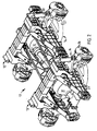
- the present invention relates to the rear axle arrangement of the vehicle 1 and Fig. 2 depicts an embodiment of a rear axle arrangement which is designed to be connected to the vehicle's chassis element 5.
- the rear axle arrangement 12 incorporates in this embodiment two rear axle units 13 which are directly connected to one another, e.g. by bolts running through (not depicted). Each rear axle unit 13 forms a self-supporting module. It should be noted that the rear axle arrangement 12 may incorporate any desired number of modules, i.e. rear axle units 13, preferably one, two or three, and if the rear axle arrangement incorporates two or more rear axle units these rear axle units may be connected directly to one another. Each rear axle unit 13 incorporates a frame structure 14 and two wheels (not depicted, although one of the wheels of each rear axle unit is depicted in Fig. 1, with reference notation 25) which are suspended on the frame structure 14.
- the frame structure 14 has a first end region 15 designed to be connected to the chassis element 5 of the vehicle 1, and a second end region 16.
- the frame structure 14 forms a space 17 which extends from the first end region 15 to the second end region 16 in the vehicle's longitudinal direction x.
- the space 17 is surrounded by two side portions 18, 19, an upper portion 20 and two lower portions 21, 22. All the portions 18, 19, 20, 21, 22 preferably incorporate aluminium castings with a view to achieving a lightweight frame structure.
- the portions 18, 19, 20, 21, 22 form, as viewed in the longitudinal direction x of the vehicle 1, a substantially quadrilateral frame round the space 17.
- the walls 6, 7, 8, 9 of the chassis element 5, as viewed in the longitudinal direction x of the vehicle 1, form a substantially quadrilateral frame round said hollow which extends along the whole length of the chassis element 5.
- Adapting the lengths of the portions 18, 19, 20, 21, 22 to the transverse lengths of the walls 6, 7, 8, 9 enables the frame structure 14 to be connected to the chassis element 5 by the first end region 15 of the frame structure 14 being inserted a short distance into said chassis element 5 so that the walls 6, 7, 8, 9 of the chassis element 5 abut to a corresponding extent against the portions 18, 19, 20 and possibly the portion 21 of the frame structure 14 and a number of bolts can extend through said walls 6, 7, 8, 9 of the chassis element 5 into the portions 18, 19, 20 and possibly the portion 21 of the frame structure 14 and connect the frame structure 14 to the chassis element 5.
- each side portion 18, 19 has a lower section 23 and an upper section 24.
- the lower sections 23 of the side portions 18, 19 are of greater extent in the longitudinal direction x, than the upper section 24, i.e. the side portions 18, 19 narrow from the lower section 23 to the upper section 24, where they are connected to the upper portion 20.
- the first lower portion 21 is arranged adjacent to the first end region 15 of the frame structure 14, and the second portion 22 is arranged adjacent to the second end region 16 of the frame structure 14.
- each rear axle unit 13 incorporates two wheels 25 depicted in Fig. 1.
- Fig. 2 omits the wheels 25 so that their suspension is depicted more clearly.
- Fig. 2 shows only the wheel hub 26 to which the wheel 25 is intended to be fitted.
- the wheel hubs 26 incorporate in a conventional manner brake discs, brake pads and other equipment for the braking of the vehicle 1. These components will not be described in more detail.
- References hereinafter to the wheels 25 include also wheel hubs, brake discs, brake pads etc.
- Each wheel 25 is individually suspended in the frame structure 14 of each rear axle unit 13.
- Each suspension incorporates a lower link arm 27 and an upper link arm 28.
- Each of the lower link arms 27 is pivotingly connected to a respective side portion 18, 19 in the vicinity of the lower section 23 of the respective side portion 18, 19 and to a respective wheel 25.
- Each of the upper link arms 28 is pivotingly connected to the respective side portion 18, 19 via a fastening device 29, and to a respective wheel 25.
- Each suspension also incorporates a spring device 30 which is connected to a respective end of the upper portion 20 via a fastening device 29 and a respective lower link arm 27.
- Each spring device 30 incorporates a spring function and a shock-absorber function.
- a differential gear 31 is arranged in the space 17 of the respective frame structure 14.
- an aperture 32 is arranged in each side portion 18, 19 of the respective frame structure 14 to make it possible for a driveshaft 33 to extend from the respective wheel 25 through the aperture 32 of the respective side portion 18, 19 to the differential gear 31 which is arranged in the space 17 of the respective frame structure 14.
- a drive connection 34 connects the two differential gears 31.
- Each rear axle unit 13 may incorporate a set of steering gear (not depicted) which makes steering of the wheels 25 of the respective rear axle unit 13 possible via a linkage arrangement.
- a towbar 35 is directly connected to the second end region 16 of the frame structure 14 via the ends of the side portions 18, 19 in the vicinity of the respective lower sections 22 of the side portions 18, 19.
- the towbar 35 is designed to make it possible to attach a trailer vehicle.
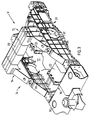
- the frame structure 14 may also incorporate a coupling device 36 in the form of a turntable on the same side as the towbar 35, as depicted in Fig. 4. Such a turntable is used when a so-called semitrailer which only incorporates a rear axle arrangement is coupled to a truck.
- the coupling device 36 replaces the upper portion 20 of the frame structure 14 in Fig. 3.
- a rear axle unit need not incorporate both a towbar and a coupling device in the form of a turntable as depicted in Fig. 4 but may incorporate only one of these alternatives.
- a coupling device 36 in the form of a turntable arranged as depicted in Fig. 4 is used where a rear axle arrangement according to the invention incorporates only one rear axle unit.
Landscapes
- Engineering & Computer Science (AREA)
- Chemical & Material Sciences (AREA)
- Combustion & Propulsion (AREA)
- Transportation (AREA)
- Mechanical Engineering (AREA)
- Vehicle Body Suspensions (AREA)
- Body Structure For Vehicles (AREA)
Applications Claiming Priority (3)
| Application Number | Priority Date | Filing Date | Title |
|---|---|---|---|
| SE9903520 | 1999-09-29 | ||
| SE9903520A SE516471C2 (sv) | 1999-09-29 | 1999-09-29 | Bakaxelanordning för ett tungt fordon |
| PCT/SE2000/001876 WO2001023244A1 (en) | 1999-09-29 | 2000-09-28 | Rear axle arrangement for a heavy vehicle |
Publications (2)
| Publication Number | Publication Date |
|---|---|
| EP1226062A1 EP1226062A1 (en) | 2002-07-31 |
| EP1226062B1 true EP1226062B1 (en) | 2004-03-24 |
Family
ID=20417196
Family Applications (1)
| Application Number | Title | Priority Date | Filing Date |
|---|---|---|---|
| EP00966664A Expired - Lifetime EP1226062B1 (en) | 1999-09-29 | 2000-09-28 | Rear axle arrangement for a heavy vehicle |
Country Status (7)
| Country | Link |
|---|---|
| US (1) | US6820900B1 (sv) |
| EP (1) | EP1226062B1 (sv) |
| JP (1) | JP2003510222A (sv) |
| BR (1) | BR0014316A (sv) |
| DE (1) | DE60009329T2 (sv) |
| SE (1) | SE516471C2 (sv) |
| WO (1) | WO2001023244A1 (sv) |
Families Citing this family (4)
| Publication number | Priority date | Publication date | Assignee | Title |
|---|---|---|---|---|
| ATE427867T1 (de) * | 2004-12-21 | 2009-04-15 | Renault Trucks | Chassis fur motorisiertes fahrzeug |
| ATE486768T1 (de) * | 2005-09-09 | 2010-11-15 | Ksm Castings Gmbh | Achsträger |
| DE102008059467A1 (de) * | 2008-11-28 | 2010-06-10 | Claas Selbstfahrende Erntemaschinen Gmbh | Landwirtschaftliche Zugmaschine |
| WO2014178761A1 (en) * | 2013-04-29 | 2014-11-06 | Volvo Truck Corporation | A heavy vehicle comprising an individual wheel suspension |
Family Cites Families (10)
| Publication number | Priority date | Publication date | Assignee | Title |
|---|---|---|---|---|
| US3243007A (en) * | 1961-05-09 | 1966-03-29 | Koehring Co | Wheel suspension for driven steerable wheels |
| US3918736A (en) * | 1974-07-22 | 1975-11-11 | Hickman Developments Inc | Tandem axle spring suspension and method of making same |
| IT1210805B (it) * | 1987-06-16 | 1989-09-29 | Ferrari Eng | Telaio posteriore facente parte di una struttura portante di una autovettura |
| US4813704A (en) * | 1988-06-20 | 1989-03-21 | Chrysler Motors Corporation | Dual strut wheel suspension |
| US4955629A (en) * | 1989-08-30 | 1990-09-11 | Todd Jr E T | Covertible chassis for a semitrailer |
| US5538274A (en) * | 1993-04-14 | 1996-07-23 | Oshkosh Truck Corporation | Modular Independent coil spring suspension |
| SE508519C2 (sv) * | 1994-06-28 | 1998-10-12 | Volvo Ab | Hjulupphängning för ett par drivna fordonshjul |
| ZA973413B (en) * | 1996-04-30 | 1998-10-21 | Autokinetics Inc | Modular vehicle frame |
| US5860668A (en) * | 1997-03-10 | 1999-01-19 | Hull; Harold L. | Semitrailer having an extendible dolly |
| US6193273B1 (en) * | 1998-08-03 | 2001-02-27 | Aluminum Company Of America | Automotive vehicle cast frame components |
-
1999
- 1999-09-29 SE SE9903520A patent/SE516471C2/sv not_active IP Right Cessation
-
2000
- 2000-09-28 DE DE60009329T patent/DE60009329T2/de not_active Expired - Lifetime
- 2000-09-28 JP JP2001526413A patent/JP2003510222A/ja active Pending
- 2000-09-28 US US10/089,639 patent/US6820900B1/en not_active Expired - Fee Related
- 2000-09-28 WO PCT/SE2000/001876 patent/WO2001023244A1/en active IP Right Grant
- 2000-09-28 BR BR0014316-2A patent/BR0014316A/pt not_active IP Right Cessation
- 2000-09-28 EP EP00966664A patent/EP1226062B1/en not_active Expired - Lifetime
Also Published As
| Publication number | Publication date |
|---|---|
| BR0014316A (pt) | 2002-05-21 |
| SE9903520L (sv) | 2001-03-30 |
| DE60009329D1 (de) | 2004-04-29 |
| DE60009329T2 (de) | 2005-02-10 |
| US6820900B1 (en) | 2004-11-23 |
| SE516471C2 (sv) | 2002-01-15 |
| JP2003510222A (ja) | 2003-03-18 |
| SE9903520D0 (sv) | 1999-09-29 |
| EP1226062A1 (en) | 2002-07-31 |
| WO2001023244A1 (en) | 2001-04-05 |
Similar Documents
| Publication | Publication Date | Title |
|---|---|---|
| EP1226063B1 (en) | Front axle arrangement for a heavy vehicle | |
| US6099039A (en) | Frame structure for sport utility vehicle or light truck | |
| US10525781B2 (en) | Mounting assembly for a suspension and wheel assembly of a vehicle, and vehicle including same | |
| US10532772B2 (en) | Mounting assembly for a suspension and wheel assembly of a vehicle, and vehicle including same | |
| JP4051471B2 (ja) | 自動車の支持構造体 | |
| CN101588955B (zh) | 特别用于重型车辆的底盘车架 | |
| CN1592696A (zh) | 车辆副车架安装 | |
| CN1970329A (zh) | 载货车的汽车车架 | |
| US4057121A (en) | Modular rear axle suspension and drive arrangement for trucks | |
| JPH0796372B2 (ja) | 全輪駆動オフロード車 | |
| CN111361376A (zh) | 油气悬架系统及工程车辆 | |
| EP1226062B1 (en) | Rear axle arrangement for a heavy vehicle | |
| EP0966361B1 (de) | Antriebsanordnung, insbesondere für omnibusse | |
| US7331590B2 (en) | Commercial vehicle suspension assembly | |
| GB2276128A (en) | Goods vehicles with separable cab and load space sections. | |
| CN105438044A (zh) | 一种全轮驱动非公路宽体自卸车 | |
| JP2018095026A (ja) | ステアリングギアボックスの取り付け構造 | |
| CN110775161A (zh) | 一种装配式货车车架总成 | |
| CN108725587B (zh) | 车架前端外伸梁支架 | |
| JPH02225183A (ja) | 自動車のための車枠/車体一体組立体 | |
| RU2196066C2 (ru) | Легковой автомобиль | |
| CN204432473U (zh) | 一种全轮驱动非公路宽体自卸车 | |
| CN216943267U (zh) | 底盘结构及电动汽车 | |
| CN220374658U (zh) | 一种新型驾驶室前端支架 | |
| CN212400810U (zh) | 油气悬架系统及工程车辆 |
Legal Events
| Date | Code | Title | Description |
|---|---|---|---|
| PUAI | Public reference made under article 153(3) epc to a published international application that has entered the european phase |
Free format text: ORIGINAL CODE: 0009012 |
|
| 17P | Request for examination filed |
Effective date: 20020429 |
|
| AK | Designated contracting states |
Kind code of ref document: A1 Designated state(s): AT BE CH CY DE DK ES FI FR GB GR IE IT LI LU MC NL PT SE |
|
| GRAP | Despatch of communication of intention to grant a patent |
Free format text: ORIGINAL CODE: EPIDOSNIGR1 |
|
| GRAS | Grant fee paid |
Free format text: ORIGINAL CODE: EPIDOSNIGR3 |
|
| GRAA | (expected) grant |
Free format text: ORIGINAL CODE: 0009210 |
|
| AK | Designated contracting states |
Kind code of ref document: B1 Designated state(s): DE FR GB IT |
|
| PG25 | Lapsed in a contracting state [announced via postgrant information from national office to epo] |
Ref country code: IT Free format text: LAPSE BECAUSE OF FAILURE TO SUBMIT A TRANSLATION OF THE DESCRIPTION OR TO PAY THE FEE WITHIN THE PRESCRIBED TIME-LIMIT;WARNING: LAPSES OF ITALIAN PATENTS WITH EFFECTIVE DATE BEFORE 2007 MAY HAVE OCCURRED AT ANY TIME BEFORE 2007. THE CORRECT EFFECTIVE DATE MAY BE DIFFERENT FROM THE ONE RECORDED. Effective date: 20040324 |
|
| REG | Reference to a national code |
Ref country code: GB Ref legal event code: FG4D |
|
| REG | Reference to a national code |
Ref country code: IE Ref legal event code: FG4D |
|
| REF | Corresponds to: |
Ref document number: 60009329 Country of ref document: DE Date of ref document: 20040429 Kind code of ref document: P |
|
| ET | Fr: translation filed | ||
| PLBE | No opposition filed within time limit |
Free format text: ORIGINAL CODE: 0009261 |
|
| STAA | Information on the status of an ep patent application or granted ep patent |
Free format text: STATUS: NO OPPOSITION FILED WITHIN TIME LIMIT |
|
| 26N | No opposition filed |
Effective date: 20041228 |
|
| REG | Reference to a national code |
Ref country code: IE Ref legal event code: MM4A |
|
| PGFP | Annual fee paid to national office [announced via postgrant information from national office to epo] |
Ref country code: FR Payment date: 20080915 Year of fee payment: 9 |
|
| PGFP | Annual fee paid to national office [announced via postgrant information from national office to epo] |
Ref country code: GB Payment date: 20081001 Year of fee payment: 9 |
|
| PGFP | Annual fee paid to national office [announced via postgrant information from national office to epo] |
Ref country code: DE Payment date: 20090923 Year of fee payment: 10 |
|
| GBPC | Gb: european patent ceased through non-payment of renewal fee |
Effective date: 20090928 |
|
| REG | Reference to a national code |
Ref country code: FR Ref legal event code: ST Effective date: 20100531 |
|
| PG25 | Lapsed in a contracting state [announced via postgrant information from national office to epo] |
Ref country code: FR Free format text: LAPSE BECAUSE OF NON-PAYMENT OF DUE FEES Effective date: 20090930 |
|
| PG25 | Lapsed in a contracting state [announced via postgrant information from national office to epo] |
Ref country code: GB Free format text: LAPSE BECAUSE OF NON-PAYMENT OF DUE FEES Effective date: 20090928 |
|
| REG | Reference to a national code |
Ref country code: DE Ref legal event code: R119 Ref document number: 60009329 Country of ref document: DE Effective date: 20110401 |
|
| PG25 | Lapsed in a contracting state [announced via postgrant information from national office to epo] |
Ref country code: DE Free format text: LAPSE BECAUSE OF NON-PAYMENT OF DUE FEES Effective date: 20110401 |