EP1225936B1 - Systeme de perfusion sous pression positive dote d'un outil de mesure de la resistance en aval - Google Patents
Systeme de perfusion sous pression positive dote d'un outil de mesure de la resistance en aval Download PDFInfo
- Publication number
- EP1225936B1 EP1225936B1 EP00968625A EP00968625A EP1225936B1 EP 1225936 B1 EP1225936 B1 EP 1225936B1 EP 00968625 A EP00968625 A EP 00968625A EP 00968625 A EP00968625 A EP 00968625A EP 1225936 B1 EP1225936 B1 EP 1225936B1
- Authority
- EP
- European Patent Office
- Prior art keywords
- pressure
- fluid
- container
- flow
- flow rate
- Prior art date
- Legal status (The legal status is an assumption and is not a legal conclusion. Google has not performed a legal analysis and makes no representation as to the accuracy of the status listed.)
- Expired - Lifetime
Links
Images


Classifications
-
- A—HUMAN NECESSITIES
- A61—MEDICAL OR VETERINARY SCIENCE; HYGIENE
- A61M—DEVICES FOR INTRODUCING MEDIA INTO, OR ONTO, THE BODY; DEVICES FOR TRANSDUCING BODY MEDIA OR FOR TAKING MEDIA FROM THE BODY; DEVICES FOR PRODUCING OR ENDING SLEEP OR STUPOR
- A61M5/00—Devices for bringing media into the body in a subcutaneous, intra-vascular or intramuscular way; Accessories therefor, e.g. filling or cleaning devices, arm-rests
- A61M5/14—Infusion devices, e.g. infusing by gravity; Blood infusion; Accessories therefor
- A61M5/142—Pressure infusion, e.g. using pumps
- A61M5/145—Pressure infusion, e.g. using pumps using pressurised reservoirs, e.g. pressurised by means of pistons
- A61M5/148—Pressure infusion, e.g. using pumps using pressurised reservoirs, e.g. pressurised by means of pistons flexible, e.g. independent bags
- A61M5/1483—Pressure infusion, e.g. using pumps using pressurised reservoirs, e.g. pressurised by means of pistons flexible, e.g. independent bags using flexible bags externally pressurised by fluid pressure
-
- A—HUMAN NECESSITIES
- A61—MEDICAL OR VETERINARY SCIENCE; HYGIENE
- A61M—DEVICES FOR INTRODUCING MEDIA INTO, OR ONTO, THE BODY; DEVICES FOR TRANSDUCING BODY MEDIA OR FOR TAKING MEDIA FROM THE BODY; DEVICES FOR PRODUCING OR ENDING SLEEP OR STUPOR
- A61M5/00—Devices for bringing media into the body in a subcutaneous, intra-vascular or intramuscular way; Accessories therefor, e.g. filling or cleaning devices, arm-rests
- A61M5/14—Infusion devices, e.g. infusing by gravity; Blood infusion; Accessories therefor
- A61M5/168—Means for controlling media flow to the body or for metering media to the body, e.g. drip meters, counters ; Monitoring media flow to the body
- A61M5/16831—Monitoring, detecting, signalling or eliminating infusion flow anomalies
- A61M5/16854—Monitoring, detecting, signalling or eliminating infusion flow anomalies by monitoring line pressure
- A61M5/16859—Evaluation of pressure response, e.g. to an applied pulse
-
- A—HUMAN NECESSITIES
- A61—MEDICAL OR VETERINARY SCIENCE; HYGIENE
- A61M—DEVICES FOR INTRODUCING MEDIA INTO, OR ONTO, THE BODY; DEVICES FOR TRANSDUCING BODY MEDIA OR FOR TAKING MEDIA FROM THE BODY; DEVICES FOR PRODUCING OR ENDING SLEEP OR STUPOR
- A61M5/00—Devices for bringing media into the body in a subcutaneous, intra-vascular or intramuscular way; Accessories therefor, e.g. filling or cleaning devices, arm-rests
- A61M5/14—Infusion devices, e.g. infusing by gravity; Blood infusion; Accessories therefor
- A61M5/168—Means for controlling media flow to the body or for metering media to the body, e.g. drip meters, counters ; Monitoring media flow to the body
- A61M5/16831—Monitoring, detecting, signalling or eliminating infusion flow anomalies
- A61M2005/16863—Occlusion detection
- A61M2005/16868—Downstream occlusion sensors
Definitions
- the invention relates generally to fluid delivery systems, and more particularly, to an intravenous (IV) infusion system having a positive-pressure based mechanism for inducing fluid flow and a monitoring system for measuring the downstream resistance of the IV infusion system based on changes in pressure and flow rate.
- IV intravenous
- IV infusion systems for infusing fluid to a patient typically include a supply of fluid for administration, an infusion needle or cannula, an administration set connecting the fluid supply to the cannula, and a flow control device.
- the administration set typically includes a flexible IV tube and a drip chamber.
- the cannula is mounted at the distal end of the flexible IV tubing for insertion into a patient's blood vessel or other body location to deliver the fluid to the patient.
- the flow control device may be either gravity-pressure based or positive-pressure based.
- Gravity-pressure based flow control devices rely on the force of gravity for fluid flow. These devices may include an "IV controller" which interfaces with the IV tube.
- An IV controller is a device that automatically controls the flow rate of fluid through the IV tube by use of a pinching device that pinches the tube more or less to control the flow of fluid therethrough.
- the IV controller is usually responsive to a control signal which is typically generated by a flow sensor attached to the drip chamber. The flow sensor senses fluid drops falling in the drip chamber. The number of drops per unit time is counted and a flow rate calculated. If the calculated flow rate is greater than a desired flow rate, the controller adjusts the pinching device to lower the flow rate by pinching the tube further.
- Graves administration sets include their relative simplicity and low cost.
- Relatively inexpensive tubing may be used such as polyvinyl chloride (“PVC”) tubing or similar type tubing.
- PVC polyvinyl chloride
- the pinching device comprises a relatively simple mechanical device under electrical control. IV controllers, however, are limited to gravity pressure, dependent upon the "head height” or “head pressure” of the administration fluid, which can be under 1 psi (0,069 bar).
- a positive-pressure based flow control device exerts a mechanical force on the fluid to establish fluid flow.
- One commonly used positive-pressure based flow control device is a linear peristaltic pump.
- a linear peristaltic pump is a complex device comprising several cams and cam-actuated fingers that sequentially occlude portions of the flexible tubing along a specially designed pumping segment to create a moving zone of occlusion. The peristaltic action forces the fluid through the tubing of the administration set to the cannula and into the patient. Because of its complexity and number of components, a linear peristaltic type pump is relatively expensive and may be undesirable in situations where cost containment is a factor. The pumping segment is also typically part of a disposable administration set and thus is relatively expensive.
- Another type of positive-pressure based flow control device is a piston-and-valve-type device that uses a specially designed plastic cassette or cylinder device that interfaces with the piston and valve to control fluid flow.
- the cassette or cylinder is small in size and has precise dimensional requirements so as to provide accurate fluid flow control. Due to such requirements these devices are expensive to manufacture.
- the cassette or cylinder is also typically part of a disposable administration set and thus have an increased cost.
- Another type of positive-pressure based flow control device includes a collapsible fluid treatment bag and an inflatable bladder.
- a fluid pump or other pressure source provides fluid, typically air, to the bladder.
- fluid typically air
- the bladder inflates, pressure is applied to the collapsible fluid treatment bag. This pressure forces fluid through the tubing of the administration set to the cannula and into the patient.
- infusion events may occur that interfere with the proper administration of fluid to the patient, such as an occlusion of the administration line. It is desirable to detect these conditions as soon as possible so that they can be remedied.
- a commonly used technique for detecting such conditions and for evaluating the operating status of the IV infusion system is to monitor the pressure in the downstream portion of the fluid delivery tube.
- the "downstream" portion of the tube is typically thought of as the portion between the flow control device, such as the pinching device in a controller or the peristaltic fingers in a linear peristaltic pump, and the patient's blood vessel.
- An increase in the downstream pressure may be caused by an occlusion.
- downstream infusion system parameters One measurement of downstream infusion system parameters that has proved useful is a measurement of resistance.
- Downstream resistance may be affected by a downstream occlusion, an infiltration of the cannula into the patient's tissue surrounding the blood vessel, a cannula that has become removed from the blood vessel, or others.
- an operator may be able to determine if any of the above events has occurred. Appropriate steps may be taken to remedy the situation sooner than with other monitoring approaches. It should be noted that when the cannula is in place in a patient's blood vessel, that blood vessel also contributes an effect to the flow and pressure in the tubing and is therefore considered part of the downstream resistance.
- Sophisticated flow control devices monitor the downstream resistance of the infusion system by altering the flow rate through the tube and measuring the corresponding change in downstream pressure. The change in pressure over the change in the flow rate has been found to accurately indicate the resistive part of the downstream fluid impedance.
- a pressure sensor is coupled to the infusion tube. The pressure sensor monitors the pressure existing in the downstream portion of the tube and produces pressure signals representing the detected pressure.
- a disadvantage of these existing systems for detecting downstream resistance is that the pressure sensor must be coupled to the IV tube. Because of this, the pressure sensors must be capable of accurately detecting fluid pressure through an IV tube. Such sensors tend to be complex and expensive.
- US 3,648,694A discloses a system for performing intravenous perfusions of a treatment liquid to a patient, the liquid being propelled by gas under pressure.
- the arrangement is intended to provide means for indicating malfunctions and avoiding accidents during transfusions such as gas emboly, thrombosis, rupture of blood vessels or detachment of a needle from a patient's vein.
- the treatment fluid is provided in a vessel or container and air is pumped into the container from a pump in order to eject the treatment fluid from the container.
- US 4,530,696 discloses a monitoring arrangement for use with an intravenous injection system.
- Treatment fluid is pumped from a container using a peristaltic pump indicated in a fluid line extending from the container.
- the fluid line passes into an accumulator or pressure moderator in which an area of gas is provided above a reservoir of the treatment fluid.
- the treatment fluid passes from the moderator through a catheter and on to the vein of a patient via a needle.
- a pressure sensor is provided to sense the pressure in the storage area of the moderator.
- FR 2 592 306A discloses a perfusion pump apparatus comprising a flexible bag containing liquid to be become perfused and a rigid device for pressurising the flexible bag, via a control unit.
- the invention is directed to an apparatus and a method for controlling fluid flow through an IV infusion system and, in another aspect, for monitoring the downstream resistance of the IV infusion system.
- apparatus for pumping infusion fluid to a catheter comprising:-
- the present invention provides a pressure-based flow control device that is free of complicated and costly peristaltic or cassette pumping means.
- the flow control device also has the capability of determining the downstream resistance in the conduit communicating with the output of the first container through the use of a standard, readily available pressure sensor at the input of the second fluid container, as opposed to a complicated and costly pressure sensor attached to the downstream region of the conduit as is common in current flow control devices.
- a very simple and inexpensive straight line gravity IV set may be used.
- the apparatus may include a pump coupled to the second fluid container for controlling the pressure within the second fluid container.
- the apparatus may include a flow control actuator coupled to the conduit downstream from the flow sensor.
- the processor may determine the downstream resistance by setting a plurality of target flow rates, measuring the pressure applied to the fluid in the first container to cause each of the plurality of target flow rates to exist at the output of the first fluid container, receiving the flow data resulting from each target flow rate and determining the impedance.
- the processor may determine the downstream resistance by controlling the pressure applied to the first container to cause a plurality of different flow rates to exist at the output of the first fluid container, receiving the flow data resulting from each flow rate and determining the impedance by processing changes in applied pressure and changes in flow together.
- a method for pumping infusion fluid from a first collapsible fluid container having an outlet communicating with a conduit comprising the steps of:
- the step of determining the downstream resistance may comprise the steps of setting a first target flow rate from the first container, applying a first pressure within the second fluid container to obtain the first target flow rate, setting a second target flow rate from the first container different than the first target flow rate, applying a second pressure within the second fluid container to obtain the second target flow rate and processing the changes in pressure and changes in target flow rate together.
- the step of determining the downstream resistance may comprise the steps of applying a first pressure within the second fluid container, sensing a first fluid-flow rate at the outlet, applying a second pressure within the second fluid container wherein the second pressure is different than the first pressure, sensing a second fluid-flow rate at the outlet, and processing the changes in pressure and changes in flow together.
- An advantage of the invention is that a relatively inexpensive administration set may be manufactured for use in the disclosed infusion system.
- a standard straight line infusion set may be used with a computer controlled pressure source and flow restriction as opposed to a peristaltic or other mechanical pumping means to regulate fluid flow under positive pressure, resulting in a less expensive system.
- the system disclosed and illustrated herein provides the performance and features of a pump without the associated cost of specially designed pumping segments.
- the system takes advantage of the characteristics of an IV controller system but overcomes the head height pressure limitations by delivering from a pressurized source.
- Such an administration set may have a conduit communicating with a collapsible bag, i. e., first container.
- the conduit may take the form of any well known spike.
- the administration set may further include a drip chamber, standard PVC tubing, a connector and a patient cannula communicating with the connector.
- the administration set may comprise a collapsible bag with an integral drip chamber and tubing coupled to a patient cannula.
- the bladder as well may be disposable and come equipped with a simple fluid connection to the pump and pressure sensor combination.
- a new and useful infusion system has been provided.
- the system described and illustrated is closed-loop for more accurate control over the infusion process.
- standard, low cost tubing and administration equipment is used for the disposable part of the system. More expensive parts, such as the processor, display, keyboard, pump and sensors may be reused thus lowering the expense.
- the ability to determine downstream resistance is provided thus giving the care giver more complete information about the infusion process. Problems that may arise during the infusion process can be detected more readily.
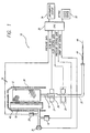
- FIG. 1 there is shown an IV infusion system 10 that utilizes a collapsible fluid container 12 and a pressure bladder 16.
- the fluid container 12 and the pressure bladder 16 are placed in a housing 14 having a rear panel 40 and a front door 38 with a transparent window (not shown) to allow the user to view the fluid container 12.
- the bladder 16 can be inflated by use of a pump 18, such as an air or other fluid pump.
- the bladder 16 is positioned relative to the fluid container 12 such that when the bladder is pressurized, the pressure from the bladder is transferred to the fluid container 12.
- the fluid container 12 is placed under pressure by the bladder 16 and the fluid within the container is forced into an IV tubing 20 communicating at one end with the outlet 42 of the container and at the other end with a catheter 44.
- the catheter 44 in turn, communicates through a cannula 46 with a patient (not shown).
- a standard, off-the-shelf, pressure sensor 22 is connected at the inlet end of the bladder 16 to monitor bladder pressure.
- a drip chamber 26 is located in the IV tubing 20 near the outlet 42 of the fluid container 12.
- a drop-detecting flow sensor 24 is positioned about the drip chamber 26 to detect fluid drops falling in the drip chamber.
- the flow sensor 24 may be any well known optical type or capacitive type sensor. Drip chambers and drop-detecting flow sensors are well known to those skilled in the art and no further details with regard to these devices are provided here.
- a flow control actuator 28 is placed about the IV tubing 20 below the drip chamber 26 to control flow.
- the actuator 28, in this embodiment, comprises a standard pinching device that subjects the infusion tubing 20 to a degree of pinching, thereby altering the inner diameter or inner opening of the tubing and thereby controlling the amount of flow through the tubing.
- the flow control actuator 28 may also be a pulse-width-modulation type rather than a degree-of-pinch type.
- a processor 30 is provided to accept user input from a keypad 32 and to display pertinent information including downstream resistance, infusion rate, time and volume on an information display 34.
- the processor 30 also receives pressure and flow-rate data from the pressure sensor 22 and the flow sensor 24 to determine the pressure, the flow rate and the downstream resistance. Based on the signals received from the sensors 22, 24, the processor 30 commands the flow control actuator 28 and the bladder pump 18 in such a way as to regulate the fluid-flow rate to the desired value entered by a user.
- the pressure bladder 16 establishes the pressure within the IV tubing 20, the drip chamber 26, the catheter 44 and the cannula 46.
- the flow control actuator 28 applies the appropriate degree of pinch to the IV tubing 20 to regulate the fluid flow rate through the downstream portion of the system, i.
- the actuator 28 is a pinching-type valve that is either entirely open with no significant contact with the tubing 20, or entirely closed wherein the tubing 20 is clamped shut.
- the amount of time that the pinching valve is in the entirely open position and the amount of time that the pinching valve is in the entirely closed position in a predetermined time frame is the duty cycle.
- the duty cycle is the comparison of the time the tubing is open to the predetermined time frame. For example, if the tubing is left open for 100 milliseconds out of each 200 milliseconds of time, the duty cycle is 50%.
- the user enters the desired infusion rate into the controller 30 using the keypad 32.
- the processor 30 determines the pressure P 0 , i . e ., the "mean pressure", and the flow control actuator duty cycle Do, necessary to establish the desired flow rate.
- the processor 30 controls the pump 18 to inflate the bladder 16 to the mean pressure.
- the bladder 16 pressure is monitored by the processor 30 through the pressure sensor 22 while the flow rate is monitored through the flow sensor 24. If the sensed flow rate is greater than the desired flow rate, the processor 30 provides flow control data to the flow control actuator 28 to set the duty cycle of the actuator to maintain the flow rate in the downstream portion of the IV tubing 20 at the desired rate.
- the duty cycle would be set at 91% to establish a 100ml/hr downstream flow rate. If, however, the sensed flow rate is less than the desired flow rate, the processor 30 may either increase the mean pressure at the bladder 16 or decrease the duty cycle of the flow control actuator 28. Naturally, if the duty cycle is set at 100%, i. e., the IV tubing 20 is completely open at all times, the only way to adjust the flow rate is to increase the mean pressure.
- the system 10 is capable of calculating the downstream resistance of the IV tubing 20 either on a periodic basis or as desired intermittently by the operator.
- the processor 30 changes the pressure within the bladder 16 by small positive deviations, ⁇ P, and negative deviations - ⁇ P, about the mean pressure and measures the flow rate changes resulting from the pressure changes.
- the flow rate is a function of both pressure and downstream resistance.
- R 1 the relationship between pressure and flow rate is rather predictable, that is, an increase or decrease in pressure produces an expected corresponding increase or decrease in flow rate.
- a significant increase or decrease in pressure produces only a slight increase or decrease in flow rate.
- the resistance line In the extreme situation where the IV tubing 20 is completely occluded, the resistance line would be substantially horizontal and no amount of pressure change will cause fluid flow change. In this situation, the flow rate will probably be zero. At a low resistance R 3 , a slight increase or decrease in pressure produces a significant increase or decrease in flow rate. In the extreme situation where the IV tubing 20 is completely unobstructed, e. g., the IV needle is no longer in the patient, the resistance line may have a large slope depending on the sizes of the tubing, catheter 44 and the cannula 46 and the change in flow rates will be large in response to pressure changes.
- the flow rate F 0 through the drip chamber 26 at pressure P 0 is first measured using data from the flow sensor 24.
- the pressure within the bladder 16 is then increased above the mean pressure P 0 by ⁇ P to pressure P 1 , as shown in FIG. 3a .
- the flow rate F 1 is then measured using data from the flow sensor 24.
- a subsequent resistance measurement is obtained by decreasing the pressure within the bladder 16 below the mean pressure P 0 by - ⁇ P to pressure P 2 .
- the flow rate F 2 is then measured using data from the flow sensor 24.
- the subsequent resistance measurement is determined by resetting the pressure to the initial pressure P 0 , measuring the flow rate F 0 and then decreasing the pressure within the bladder 16 below the mean pressure P 0 by - ⁇ P to pressure P 2.
- the frequency of downstream resistance measurement may be set by the processor or set by the operator through the keypad 32.
- two consecutive frequency measurements are calculated using Eqs. 1 and 2. These two measurements may be averaged to obtain a single resistance measurement.
- the time between the next pair of positive and negative pressure deviations defines the frequency.
- the positive pressure deviation provides a resistance measurement using Eq. 1.
- the negative pressure deviation provides a resistance measurement using Eq. 3.
- the time between the positive and negative deviations may define the frequency.
- the positive and negative deviations occur substantially close to each other they may be considered a deviation pair, similar to the deviation pair of FIG. 3a , and the time between the next pair of positive and negative pressure deviations defines the frequency.
- a resistance measurement may also be received on command by the operator through the keypad 32.
- the flow control actuator 28 operates at a fixed duty cycle, thereby maintaining the desired flow rate in the downstream portion of the system.
- the flow control actuator 28 compresses the IV tubing 20 in accordance with the fixed duty cycle selected to maintain the desired flow rate in the downstream portion of the system.
- the average flow rate within the drip chamber 26 is maintained by the small positive ⁇ P and small negative - ⁇ P pressure deviations from the mean P 0 , as shown in FIGS. 3a and 4a , which in the aggregate, cancel each other out to maintain an average flow rate within the drip chamber substantially equal to the desired flow rate.
- step S1 the pressure P of the bladder 16 is set to P 0 and the duty cycle D of the flow control actuator 28 is set to Do to establish a flow rate F 0 .
- step S2 the flow rate F within the drip chamber 26 is measured.
- step S3 it is determined whether the measured flow rate F equals the desired flow rate F 0 . If no, then the pressure P 0 and/or duty cycle Do are adjusted in step S4 and the process returns to step S2.
- step S5 it is determined whether it is time to perform a resistance measurement. If it is not yet time, the process returns to step S2. If it is time to perform a resistance measurement, the duty cycle is fixed at Do in step S6.
- step S8 the flow rate F 1 within the drip chamber 26 is measured.
- step S9 the downstream resistance is calculated using Eq. 1.
- step S11 the flow rate F 2 within the drip chamber 26 is measured.
- step S12 the downstream resistance is calculated using Eq. 2.
- step S13 the bladder pressure P is set to P 0 and the process returns to step S2.
- step S21 the pressure P of the bladder 16 is set to P 0 and the duty cycle D of the flow control actuator 28 is set to Do to establish a flow rate F 0 .
- step S22 the flow rate F within the drip chamber 26 is measured.
- step S23 it is determined whether the measured flow rate F equals the desired flow rate F 0 . If no, then the pressure P 0 and/or duty cycle Do are adjusted in step S24 and the process returns to step S22.
- step S25 it is determined whether it is time to perform a resistance measurement. If it is not yet time, the process returns to step S22. If it is time to perform a resistance measurement, the duty cycle is fixed at Do in step S26.
- step S27 a first target flow rate F 1 is set to F 0 + ⁇ F.
- step S28 it is determined whether the measured flow rate F equals the first target flow rate F 1 . If no, then the pressure P 0 is increased by an incremental amount in step S29 and the process returns to step S28. If yes, then in step S30 the pressure P 1 is measured, where P 1 is the pressure required to achieve the first target flow rate F 1 .
- step S31 a second target flow rate F 2 is set to F 0 - ⁇ F.
- step S32 it is determined whether the measured flow rate F equals the second target flow rate F 2 . If no, then the pressure P 0 is decreased by an incremental amount in step S33 and the process returns to step S32. If yes, then in step S34 the pressure P 2 is measured, where P 2 is the pressure required to achieve the second target flow rate F 2 .
- step S35 the downstream resistance is calculated using Eq. 2.
- step S36 the bladder pressure P is set to P 0 and the process returns to step S22.
- this version of operation is better able to maintain the average flow rate within the drip chamber near F 0 .
- the processor monitors for alarm conditions.
- alarm conditions may include system occlusion conditions and system disconnect conditions.
- a system occlusion is detected when the flow data provided by the flow sensor 24 indicates a flow rate that is less than expected for a given applied pressure. The larger the flow-rate deviates from the expected flow rate the more significant the system occlusion. In the extreme case, if the flow rate is zero, a complete occlusion is likely.
- a system occlusion may occur in the downstream portion of the system or in the portion of the system between the fluid container 12 and the flow control actuator 28.
- a system disconnect is detected when the flow data provided by the flow sensor 24 indicates a flow rate that is significantly greater than expected for a given applied pressure.
- a system disconnect may occur when the tubing 20 disconnects from the catheter 44, when the catheter disconnects from the cannula 46 or when the cannula disconnects from the patient.
- the processor 30 may, if desired, automatically activate a dump valve 36 to rapidly depressurize the bladder 16 thereby stopping further fluid flow from the fluid container 12 to the IV tubing 20.
- the processor 30 may also stop signaling the flow control actuator 28 causing it to pinch the IV tubing 20 completely shut thereby stopping further fluid flow to the patient.
Landscapes
- Health & Medical Sciences (AREA)
- Vascular Medicine (AREA)
- Engineering & Computer Science (AREA)
- Anesthesiology (AREA)
- Biomedical Technology (AREA)
- Heart & Thoracic Surgery (AREA)
- Hematology (AREA)
- Life Sciences & Earth Sciences (AREA)
- Animal Behavior & Ethology (AREA)
- General Health & Medical Sciences (AREA)
- Public Health (AREA)
- Veterinary Medicine (AREA)
- Physics & Mathematics (AREA)
- Fluid Mechanics (AREA)
- Infusion, Injection, And Reservoir Apparatuses (AREA)
- Measuring And Recording Apparatus For Diagnosis (AREA)
- Measuring Fluid Pressure (AREA)
Claims (20)
- Dispositif pour pomper un fluide de perfusion vers un cathéter (44), ledit dispositif comprenant:un premier récipient de fluide déformable (12);un conduit connecté à une sortie (42) du premier récipient de fluide (12) et configuré pour être placé en communication fluide avec un tel cathéter (44) pour permettre à un fluide de s'écouler dudit premier récipient vers ledit cathéter;un second récipient de fluide dilatable (16), de commande par pression, situé de manière adjacente au premier récipient de manière à ce qu'une alimentation en fluide sous pression vers ledit second récipient applique une force mécanique contre le premier récipient pour amener ce dernier à se déformer et à expulser son contenu dans le conduit, et ce d'une manière contrôlable;un capteur d'écoulement (24) couplé au conduit et adapté pour détecter un écoulement de fluide dans le conduit et fournir des signaux d'écoulement en réponse à l'écoulement de fluide détecté;caractérisé par le fait que le dispositif comprend, en outre:un capteur de pression (22) couplé au second récipient de fluide (16) et adapté pour détecter la pression dans le second récipient de fluide et fournir des signaux de pression en réponse à la pression détectée; etun processeur (30) sensible au signaux de pression et aux signaux d'écoulement et pouvant fonctionner pour déterminer la résistance à l'écoulement de fluide à travers le conduit en aval du premier récipient sur la base desdits signaux d'écoulement et signaux de pression.
- Dispositif selon la revendication 1, comprenant, en outre, une pompe (18) couplée au second récipient de fluide (16) pour commander la pression à l'intérieur du second récipient de fluide.
- Dispositif selon la revendication 2, dans lequel la pompe (18) est sensible à des données de commande de pression venant du processeur (30).
- Dispositif selon la revendication 1, comprenant, en outre, un actionneur de commande d'écoulement (28) couplé au conduit en aval du capteur d'écoulement (24).
- Dispositif selon la revendication 4, dans lequel l'actionneur de commande d'écoulement (28) est sensible à des données de commande d'écoulement venant du processeur (30).
- Dispositif selon la revendication 1, dans lequel le second récipient de fluide (16) inclut une entrée et comprenant, en outre, une soupape de décharge (36) couplée à l'entrée du second récipient de fluide.
- Dispositif selon la revendication 6, dans lequel la soupape de décharge (36) est sensible à des données de commande de soupape de décharge venant du processeur (30).
- Dispositif selon la revendication 1, comprenant, en outre, un écran (34) répondant au processeur (30) pour afficher des mesures de résistance en aval.
- Dispositif selon la revendication 1, comprenant, en outre, un dispositif d'entrée d'utilisateur couplé au processeur (30) pour entrer des données sur un débit souhaité.
- Dispositif selon la revendication 1, dans lequel le processeur (30) est couplé fonctionnellement au second récipient pour commander la pression appliquée par le second récipient sur le premier récipient (12) de manière à faire exister une pluralité de débits différents à la sortie du premier récipient de fluide, le processeur étant configuré, en outre, pour déterminer ladite résistance à l'écoulement de fluide en traitant des signaux d'écoulement et de pression représentant des changements dans la pression appliquée et des changements de débit correspondants.
- Dispositif selon la revendication 1, dans lequel le processeur (30) est configuré pour fixer une pluralité de débits cibles, mesurer la pression appliquée au fluide dans le premier récipient (12) pour faire en sorte que chaque débit de la pluralité de débits cibles existe à la sortie (42) du premier récipient de fluide, et pour déterminer ladite résistance à l'écoulement de fluide en traitant des signaux d'écoulement et de pression représentant des changements dans la pression appliquée et des changements de débit correspondants.
- Dispositif selon la revendication 11, dans lequel la pluralité de débits cibles présente de petits écarts positifs et négatifs par rapport à un débit moyen pour maintenir une moyenne de débit sensiblement égale au débit moyen.
- Procédé pour pomper un fluide de perfusion depuis un premier récipient de fluide déformable (12) pourvu d'une sortie (42) communiquant avec un conduit (20), ledit procédé comprenant les étapes de:positionnement d'un second récipient de fluide dilatable (16), de commande par pression, à l'intérieur du boîtier de manière adjacente au premier récipient de fluide de manière à ce qu'une alimentation en fluide sous pression vers ledit second récipient applique une force mécanique contre le premier récipient pour amener ce dernier à se déformer et à expulser son contenu dans le conduit, et ce d'une manière contrôlable;application d'une pression de fluide audit second conteneur pour appliquer une force mécanique contre le premier récipient pour amener ce dernier à se déformer et à expulser son contenu en fluide de perfusion à travers ledit conduit (20); etdétection de la vitesse d'écoulement de fluide à travers ledit conduit;caractérisé par la détection de la pression de fluide dans ledit second récipient et la détermination de la résistance à l'écoulement de fluide à travers le conduit en aval du premier récipient sur la base de la pression et de l'écoulement détectés.
- Procédé selon la revendication 13, dans lequel l'étape de détermination de la résistance en aval comprend les étapes de:application d'une première pression à l'intérieur du second récipient de fluide (16);détection d'un premier débit de fluide à la sortie (42);application d'une seconde pression à l'intérieur du second récipient de fluide, la seconde pression étant différente de la première pression;détection d'un second débit de fluide à la sortie; ettraitement conjoint des changements de pression et des changements de débit.
- Procédé selon la revendication 14, dans lequel une des pressions, soit la première, soit la seconde, est la pression moyenne.
- Procédé selon la revendication 14, dans lequel la première pression et la seconde pression présentent un écart positif et un écart négatif, respectivement, par rapport à une pression moyenne dans le second récipient pour maintenir une moyenne de pression sensiblement égale à la pression moyenne.
- Procédé selon la revendication 13, dans lequel l'étape de détermination de la résistance en aval comprend les étapes de:fixation d'un premier débit cible depuis le premier récipient (12);application d'une première pression à l'intérieur du second récipient de fluide (16) pour obtenir le premier débit cible;fixation d'un second débit cible depuis le premier récipient, qui est différent du premier débit cible;application d'une seconde pression à l'intérieur du second récipient de fluide pour obtenir le second débit cible;traitement conjoint des changements de pression et des changements de débit cible.
- Procédé selon la revendication 17, dans lequel un des débits cibles, soit le premier, soit le second, est le débit moyen.
- Procédé selon la revendication 17, dans lequel le premier débit cible et le second débit cible présentent un écart positif et un écart négatif, respectivement, par rapport au débit moyen, pour maintenir une moyenne de débit sensiblement égale au débit moyen.
- Procédé selon la revendication 17, comprenant, en outre, les étapes de maintien du débit en aval sensiblement constant en déterminant la résistance en aval.
Priority Applications (3)
| Application Number | Priority Date | Filing Date | Title |
|---|---|---|---|
| EP10012529A EP2286856A3 (fr) | 1999-10-27 | 2000-10-03 | Système de perfusion à pression positive avec capacité de mesurer la résistence en aval |
| DK08010292.4T DK1964584T3 (da) | 1999-10-27 | 2000-10-03 | System til positiv trykinfusion med mulighed for måling af nedstrømsmodstand |
| EP08010292A EP1964584B1 (fr) | 1999-10-27 | 2000-10-03 | Système de perfusion à pression positive avec capacité de mesurer la résistence en aval |
Applications Claiming Priority (3)
| Application Number | Priority Date | Filing Date | Title |
|---|---|---|---|
| US09/428,006 US7255680B1 (en) | 1999-10-27 | 1999-10-27 | Positive pressure infusion system having downstream resistance measurement capability |
| US428006 | 1999-10-27 | ||
| PCT/US2000/027267 WO2001030422A1 (fr) | 1999-10-27 | 2000-10-03 | Systeme de perfusion sous pression positive dote d'un outil de mesure de la resistance en aval |
Related Child Applications (1)
| Application Number | Title | Priority Date | Filing Date |
|---|---|---|---|
| EP08010292A Division EP1964584B1 (fr) | 1999-10-27 | 2000-10-03 | Système de perfusion à pression positive avec capacité de mesurer la résistence en aval |
Publications (2)
| Publication Number | Publication Date |
|---|---|
| EP1225936A1 EP1225936A1 (fr) | 2002-07-31 |
| EP1225936B1 true EP1225936B1 (fr) | 2008-08-20 |
Family
ID=23697189
Family Applications (3)
| Application Number | Title | Priority Date | Filing Date |
|---|---|---|---|
| EP08010292A Expired - Lifetime EP1964584B1 (fr) | 1999-10-27 | 2000-10-03 | Système de perfusion à pression positive avec capacité de mesurer la résistence en aval |
| EP00968625A Expired - Lifetime EP1225936B1 (fr) | 1999-10-27 | 2000-10-03 | Systeme de perfusion sous pression positive dote d'un outil de mesure de la resistance en aval |
| EP10012529A Withdrawn EP2286856A3 (fr) | 1999-10-27 | 2000-10-03 | Système de perfusion à pression positive avec capacité de mesurer la résistence en aval |
Family Applications Before (1)
| Application Number | Title | Priority Date | Filing Date |
|---|---|---|---|
| EP08010292A Expired - Lifetime EP1964584B1 (fr) | 1999-10-27 | 2000-10-03 | Système de perfusion à pression positive avec capacité de mesurer la résistence en aval |
Family Applications After (1)
| Application Number | Title | Priority Date | Filing Date |
|---|---|---|---|
| EP10012529A Withdrawn EP2286856A3 (fr) | 1999-10-27 | 2000-10-03 | Système de perfusion à pression positive avec capacité de mesurer la résistence en aval |
Country Status (11)
| Country | Link |
|---|---|
| US (1) | US7255680B1 (fr) |
| EP (3) | EP1964584B1 (fr) |
| AT (2) | ATE496648T1 (fr) |
| AU (1) | AU7850900A (fr) |
| CY (1) | CY1112528T1 (fr) |
| DE (2) | DE60040006D1 (fr) |
| DK (2) | DK1964584T3 (fr) |
| ES (2) | ES2310522T3 (fr) |
| HK (1) | HK1119982A1 (fr) |
| PT (2) | PT1225936E (fr) |
| WO (1) | WO2001030422A1 (fr) |
Families Citing this family (93)
| Publication number | Priority date | Publication date | Assignee | Title |
|---|---|---|---|---|
| US6985870B2 (en) | 2002-01-11 | 2006-01-10 | Baxter International Inc. | Medication delivery system |
| US10173008B2 (en) | 2002-01-29 | 2019-01-08 | Baxter International Inc. | System and method for communicating with a dialysis machine through a network |
| DE10224750A1 (de) | 2002-06-04 | 2003-12-24 | Fresenius Medical Care De Gmbh | Vorrichtung zur Behandlung einer medizinischen Flüssigkeit |
| US7008403B1 (en) * | 2002-07-19 | 2006-03-07 | Cognitive Ventures Corporation | Infusion pump and method for use |
| US9033920B2 (en) * | 2003-10-02 | 2015-05-19 | Medtronic, Inc. | Determining catheter status |
| US7320676B2 (en) * | 2003-10-02 | 2008-01-22 | Medtronic, Inc. | Pressure sensing in implantable medical devices |
| US9138537B2 (en) * | 2003-10-02 | 2015-09-22 | Medtronic, Inc. | Determining catheter status |
| US8323244B2 (en) * | 2007-03-30 | 2012-12-04 | Medtronic, Inc. | Catheter malfunction determinations using physiologic pressure |
| US7492167B2 (en) * | 2003-11-05 | 2009-02-17 | Yeda Research And Development Co. Ltd. | Method and device for monitoring and controlling fluid locomotion |
| US7935074B2 (en) | 2005-02-28 | 2011-05-03 | Fresenius Medical Care Holdings, Inc. | Cassette system for peritoneal dialysis machine |
| US8197231B2 (en) | 2005-07-13 | 2012-06-12 | Purity Solutions Llc | Diaphragm pump and related methods |
| US7837673B2 (en) * | 2005-08-08 | 2010-11-23 | Innovative Therapies, Inc. | Wound irrigation device |
| EP2013793A4 (fr) * | 2006-02-27 | 2010-01-06 | Fluidnet Corp | Mesure des volumes en utilisant les principes des gaz |
| US20110028937A1 (en) * | 2006-02-27 | 2011-02-03 | Fluidnet Corporation | Automated fluid flow control system |
| US10010686B2 (en) | 2006-02-27 | 2018-07-03 | Ivenix, Inc. | Fluid control system and disposable assembly |
| WO2007098265A2 (fr) | 2006-02-27 | 2007-08-30 | Fluidnet Corporation | Capteur de débit étalonné par des modifications de volume |
| WO2007123764A2 (fr) * | 2006-04-06 | 2007-11-01 | Medtronic, Inc. | Systèmes et procédés permettant d'identifier un dysfonctionnement de cathéter au moyen d'une détection de pression |
| TWI329414B (en) * | 2006-12-18 | 2010-08-21 | Delta Electronics Inc | Adjusting method and device of sensitivity of signal determination |
| US9044537B2 (en) | 2007-03-30 | 2015-06-02 | Medtronic, Inc. | Devices and methods for detecting catheter complications |
| AU2008236665B2 (en) * | 2007-04-03 | 2013-08-22 | Nuvasive, Inc. | Neurophysiologic monitoring system |
| US8388567B2 (en) * | 2007-04-12 | 2013-03-05 | Gambro Lundia Ab | Apparatus for extracorporeal blood treatment |
| US20090191067A1 (en) * | 2008-01-25 | 2009-07-30 | Phluid,Inc. | Two chamber pumps and related methods |
| US8986253B2 (en) | 2008-01-25 | 2015-03-24 | Tandem Diabetes Care, Inc. | Two chamber pumps and related methods |
| US20090270844A1 (en) * | 2008-04-24 | 2009-10-29 | Medtronic, Inc. | Flow sensor controlled infusion device |
| DE102008035742B3 (de) * | 2008-07-04 | 2010-01-14 | Fresenius Medical Care Deutschland Gmbh | Vorrichtung zur Peritonealdialyse |
| US10089443B2 (en) | 2012-05-15 | 2018-10-02 | Baxter International Inc. | Home medical device systems and methods for therapy prescription and tracking, servicing and inventory |
| US8554579B2 (en) | 2008-10-13 | 2013-10-08 | Fht, Inc. | Management, reporting and benchmarking of medication preparation |
| US8197235B2 (en) | 2009-02-18 | 2012-06-12 | Davis David L | Infusion pump with integrated permanent magnet |
| US8353864B2 (en) | 2009-02-18 | 2013-01-15 | Davis David L | Low cost disposable infusion pump |
| US8192401B2 (en) | 2009-03-20 | 2012-06-05 | Fresenius Medical Care Holdings, Inc. | Medical fluid pump systems and related components and methods |
| CA2767668C (fr) | 2009-07-15 | 2017-03-07 | Fresenius Medical Care Holdings, Inc. | Cassettes de fluide medical et systemes et procedes afferents |
| EP2932994B1 (fr) | 2009-07-30 | 2017-11-08 | Tandem Diabetes Care, Inc. | Nouveau joint torique, mécanisme de distribution et système de pompe de perfusion portable qui lui sont associés |
| US8720913B2 (en) | 2009-08-11 | 2014-05-13 | Fresenius Medical Care Holdings, Inc. | Portable peritoneal dialysis carts and related systems |
| US8579859B2 (en) * | 2009-12-26 | 2013-11-12 | Board Of Regents, The University Of Texas System | Fluid balance monitoring system with fluid infusion pump for medical treatment |
| US20140228755A1 (en) * | 2009-12-26 | 2014-08-14 | Athena Gtx, Inc. | Fluid Balance Monitoring System with Fluid Infusion Pump for Medical Treatment |
| US8529491B2 (en) * | 2009-12-31 | 2013-09-10 | Fresenius Medical Care Holdings, Inc. | Detecting blood flow degradation |
| WO2013095459A1 (fr) * | 2011-12-21 | 2013-06-27 | Deka Products Limited Partnership | Système, procédé et appareil pour des soins électroniques prodigués à des patients |
| US9151646B2 (en) | 2011-12-21 | 2015-10-06 | Deka Products Limited Partnership | System, method, and apparatus for monitoring, regulating, or controlling fluid flow |
| EP3511049A3 (fr) * | 2010-03-04 | 2019-11-06 | PAVmed, Inc. | Systèmes et procédés d'injection de fluides utilisant une énergie potentielle stockée et une résistance à débit variable |
| US9392953B1 (en) * | 2010-09-17 | 2016-07-19 | Nuvasive, Inc. | Neurophysiologic monitoring |
| JP2012066004A (ja) * | 2010-09-27 | 2012-04-05 | Ricoh Co Ltd | 送液システム、送液方法及びプログラム |
| DE102010053973A1 (de) | 2010-12-09 | 2012-06-14 | Fresenius Medical Care Deutschland Gmbh | Medizinisches Gerät mit einer Heizung |
| EP2654825B1 (fr) | 2010-12-20 | 2017-08-02 | Fresenius Medical Care Holdings, Inc. | Cassettes de fluide médical et systèmes et procédés afférents |
| US10335230B2 (en) * | 2011-03-09 | 2019-07-02 | Covidien Lp | Systems for thermal-feedback-controlled rate of fluid flow to fluid-cooled antenna assembly and methods of directing energy to tissue using same |
| US9624915B2 (en) | 2011-03-09 | 2017-04-18 | Fresenius Medical Care Holdings, Inc. | Medical fluid delivery sets and related systems and methods |
| AU2012254069B2 (en) | 2011-04-21 | 2015-10-08 | Fresenius Medical Care Holdings, Inc. | Medical fluid pumping systems and related devices and methods |
| US9186449B2 (en) | 2011-11-01 | 2015-11-17 | Fresenius Medical Care Holdings, Inc. | Dialysis machine support assemblies and related systems and methods |
| US10228683B2 (en) | 2011-12-21 | 2019-03-12 | Deka Products Limited Partnership | System, method, and apparatus for monitoring, regulating, or controlling fluid flow |
| US9746093B2 (en) | 2011-12-21 | 2017-08-29 | Deka Products Limited Partnership | Flow meter and related system and apparatus |
| US10488848B2 (en) * | 2011-12-21 | 2019-11-26 | Deka Products Limited Partnership | System, method, and apparatus for monitoring, regulating, or controlling fluid flow |
| US9180242B2 (en) | 2012-05-17 | 2015-11-10 | Tandem Diabetes Care, Inc. | Methods and devices for multiple fluid transfer |
| US9555186B2 (en) | 2012-06-05 | 2017-01-31 | Tandem Diabetes Care, Inc. | Infusion pump system with disposable cartridge having pressure venting and pressure feedback |
| US9610392B2 (en) | 2012-06-08 | 2017-04-04 | Fresenius Medical Care Holdings, Inc. | Medical fluid cassettes and related systems and methods |
| US9500188B2 (en) | 2012-06-11 | 2016-11-22 | Fresenius Medical Care Holdings, Inc. | Medical fluid cassettes and related systems and methods |
| US10010673B2 (en) | 2012-08-28 | 2018-07-03 | Osprey Medical, Inc. | Adjustable medium diverter |
| KR101623326B1 (ko) | 2012-10-26 | 2016-05-20 | 백스터 코포레이션 잉글우드 | 의료 투여분 조제 시스템을 위한 개선된 작업 스테이션 |
| EP3779876A1 (fr) | 2012-10-26 | 2021-02-17 | Baxter Corporation Englewood | Acquisition d'images améliorées pour système de préparation de doses médicales |
| US11877860B2 (en) | 2012-11-06 | 2024-01-23 | Nuvasive, Inc. | Systems and methods for performing neurophysiologic monitoring during spine surgery |
| US11259737B2 (en) | 2012-11-06 | 2022-03-01 | Nuvasive, Inc. | Systems and methods for performing neurophysiologic monitoring during spine surgery |
| US9757067B1 (en) | 2012-11-09 | 2017-09-12 | Nuvasive, Inc. | Systems and methods for performing neurophysiologic monitoring during spine surgery |
| US9759343B2 (en) | 2012-12-21 | 2017-09-12 | Deka Products Limited Partnership | Flow meter using a dynamic background image |
| US9757072B1 (en) | 2013-02-11 | 2017-09-12 | Nuvasive, Inc. | Waveform marker placement algorithm for use in neurophysiologic monitoring |
| US9038861B2 (en) | 2013-03-14 | 2015-05-26 | Usc, L.L.C. | Seed metering wheel assembly |
| US20140271243A1 (en) * | 2013-03-14 | 2014-09-18 | Usc, L.L.C. | Pump stand with improved pump control |
| US9173998B2 (en) | 2013-03-14 | 2015-11-03 | Tandem Diabetes Care, Inc. | System and method for detecting occlusions in an infusion pump |
| US9561323B2 (en) | 2013-03-14 | 2017-02-07 | Fresenius Medical Care Holdings, Inc. | Medical fluid cassette leak detection methods and devices |
| US9180243B2 (en) | 2013-03-15 | 2015-11-10 | Tandem Diabetes Care, Inc. | Detection of infusion pump conditions |
| US20140276569A1 (en) | 2013-03-15 | 2014-09-18 | Tandem Diabetes Care, Inc. | System and method for detecting presence of an infusion cartridge in an infusion pump |
| US9421329B2 (en) | 2013-03-15 | 2016-08-23 | Tandem Diabetes Care, Inc. | Infusion device occlusion detection system |
| US9433721B2 (en) | 2013-06-25 | 2016-09-06 | Fresenius Medical Care Holdings, Inc. | Vial spiking assemblies and related methods |
| GB2515751A (en) * | 2013-07-01 | 2015-01-07 | Tap Biosystems Phc Ltd | Bioreactor consumable units |
| US10117985B2 (en) | 2013-08-21 | 2018-11-06 | Fresenius Medical Care Holdings, Inc. | Determining a volume of medical fluid pumped into or out of a medical fluid cassette |
| CN105848694B (zh) * | 2013-11-15 | 2020-01-24 | 艾韦尼克斯股份有限公司 | 流体控制系统和一次性组件 |
| US10607508B2 (en) | 2013-11-19 | 2020-03-31 | Forschungs- Und Transferzentrum Leipzig E.V. An Der Hochschule Für Technik, Wirtschaft Und Kultur Leipzig | Modular surgical training system |
| DE102013112746A1 (de) * | 2013-11-19 | 2015-05-21 | Forschungs- und Transferzentrum Leipzig e.V. an der Hochschule für Technik, Wirtschaft und Kultur Leipzig (FH) | Modulares chirurgisches Trainingssystem |
| US20150182697A1 (en) | 2013-12-31 | 2015-07-02 | Abbvie Inc. | Pump, motor and assembly for beneficial agent delivery |
| US11007082B2 (en) | 2014-07-23 | 2021-05-18 | Innovative Therapies Inc. | Foam laminate dressing |
| JP6713456B2 (ja) * | 2014-09-11 | 2020-06-24 | オスプレイ メディカル インコーポレイテッド | 分流された媒体を収集し再使用するためのリザーバ |
| US10420480B1 (en) | 2014-09-16 | 2019-09-24 | Nuvasive, Inc. | Systems and methods for performing neurophysiologic monitoring |
| US11107574B2 (en) | 2014-09-30 | 2021-08-31 | Baxter Corporation Englewood | Management of medication preparation with formulary management |
| SG11201704359VA (en) | 2014-12-05 | 2017-06-29 | Baxter Corp Englewood | Dose preparation data analytics |
| EP3800610A1 (fr) | 2015-03-03 | 2021-04-07 | Baxter Corporation Englewood | Gestion de flux de travail en pharmacie avec alertes intégrées |
| US10232130B2 (en) | 2015-03-26 | 2019-03-19 | Becton, Dickinson And Company | Anti-run dry membrane |
| US10702689B2 (en) | 2015-03-26 | 2020-07-07 | Becton, Dickinson And Company | Auto-stop vent plug |
| US10201667B2 (en) | 2015-03-26 | 2019-02-12 | Becton, Dickinson And Company | IV membrane attachment systems and methods |
| US10646648B2 (en) | 2015-04-01 | 2020-05-12 | Becton, Dickinson And Company | IV flow management systems and methods |
| US10183130B2 (en) | 2015-04-29 | 2019-01-22 | Carefusion 303, Inc. | Measuring valve health by pressure monitoring |
| US9974942B2 (en) | 2015-06-19 | 2018-05-22 | Fresenius Medical Care Holdings, Inc. | Non-vented vial drug delivery |
| MX2018009239A (es) | 2016-01-28 | 2019-02-07 | Deka Products Lp | Aparato para monitorizar, regular o controlar el flujo de fluidos. |
| USD854145S1 (en) | 2016-05-25 | 2019-07-16 | Deka Products Limited Partnership | Apparatus to control fluid flow through a tube |
| CN113811709A (zh) | 2019-04-10 | 2021-12-17 | 帕夫梅德有限公司 | 用于可变流阻滞器的系统和方法 |
| USD964563S1 (en) | 2019-07-26 | 2022-09-20 | Deka Products Limited Partnership | Medical flow clamp |
| US11839741B2 (en) | 2019-07-26 | 2023-12-12 | Deka Products Limited Partneship | Apparatus for monitoring, regulating, or controlling fluid flow |
Family Cites Families (24)
| Publication number | Priority date | Publication date | Assignee | Title |
|---|---|---|---|---|
| US3648694A (en) | 1968-09-25 | 1972-03-14 | Inst Oncologic Bucharest | Automatic system with perfusion protection against malfunction |
| ZA726230B (en) | 1971-09-28 | 1973-05-30 | Bestnu Eng Ltd | Intravenous fluids administration apparatus |
| US4397648A (en) | 1980-11-07 | 1983-08-09 | Ivac Corporation | Drop sensing unit and associated drip chamber for IV fluid administration |
| US4447224A (en) * | 1982-09-20 | 1984-05-08 | Infusaid Corporation | Variable flow implantable infusion apparatus |
| US4530696A (en) | 1983-06-13 | 1985-07-23 | Institute Of Critical Care Medicine | Monitor for intravenous injection system for detecting occlusion and/or infiltration |
| US4613327A (en) | 1984-01-26 | 1986-09-23 | Tegrarian Haig V | Apparatus for infusing blood and other related fluids into a patient's body |
| US4661246A (en) * | 1984-10-01 | 1987-04-28 | Ash Medical Systems, Inc. | Dialysis instrument with dialysate side pump for moving body fluids |
| US4718022A (en) * | 1985-02-21 | 1988-01-05 | Cochran Michael J | Dialysis machine which anticipates concentration changes |
| US4626241A (en) | 1985-03-06 | 1986-12-02 | Ivac Corporation | Apparatus and method for controlling the parenteral administration of fluids |
| FR2592306A1 (fr) | 1985-12-30 | 1987-07-03 | Couegnas Jacques | Appareil de perfusion a debit reglable ne provoquant pas de modification du liquide perfuse. |
| US4778451A (en) | 1986-03-04 | 1988-10-18 | Kamen Dean L | Flow control system using boyle's law |
| US4898576A (en) | 1986-06-06 | 1990-02-06 | Philip James H | Intravenous fluid flow monitor |
| US4919596A (en) | 1987-12-04 | 1990-04-24 | Pacesetter Infusion, Ltd. | Fluid delivery control and monitoring apparatus for a medication infusion system |
| US5096385A (en) | 1989-11-08 | 1992-03-17 | Ivac Corporation | Method and system for upstream occlusion detection |
| US5163909A (en) | 1991-01-28 | 1992-11-17 | Alan E. Jordan | Medical fluid delivery system |
| US5207645A (en) | 1991-06-25 | 1993-05-04 | Medication Delivery Devices | Infusion pump, treatment fluid bag therefor, and method for the use thereof |
| USRE35501E (en) | 1991-06-25 | 1997-05-06 | Medication Delivery Devices | Infusion pump, treatment fluid bag therefor, and method for the use thereof |
| US5277820A (en) * | 1992-02-06 | 1994-01-11 | Hemocleanse, Inc. | Device and method for extracorporeal blood treatment |
| US6156007A (en) * | 1992-09-04 | 2000-12-05 | Hemotherm, Inc. | Apparatus for whole-body hyperthermia |
| US5411482A (en) | 1992-11-02 | 1995-05-02 | Infusion Technologies Corporation | Valve system and method for control of an infusion pump |
| CA2083555A1 (fr) | 1992-11-23 | 1994-05-24 | David H. Laing | Infuseur portable |
| US5348539A (en) | 1993-06-29 | 1994-09-20 | Glenn Herskowitz | Infusion pump for use with prepackaged IV bags |
| US5609576A (en) | 1994-09-13 | 1997-03-11 | Ivac Medical Systems, Inc. | Fluid flow impedance monitoring system |
| JP2000316970A (ja) * | 1999-05-10 | 2000-11-21 | Medicos Hirata:Kk | 自動制御式ポータブル点滴装置 |
-
1999
- 1999-10-27 US US09/428,006 patent/US7255680B1/en not_active Expired - Lifetime
-
2000
- 2000-10-03 ES ES00968625T patent/ES2310522T3/es not_active Expired - Lifetime
- 2000-10-03 ES ES08010292T patent/ES2363115T3/es not_active Expired - Lifetime
- 2000-10-03 AT AT08010292T patent/ATE496648T1/de active
- 2000-10-03 EP EP08010292A patent/EP1964584B1/fr not_active Expired - Lifetime
- 2000-10-03 DK DK08010292.4T patent/DK1964584T3/da active
- 2000-10-03 PT PT00968625T patent/PT1225936E/pt unknown
- 2000-10-03 DE DE60040006T patent/DE60040006D1/de not_active Expired - Lifetime
- 2000-10-03 PT PT08010292T patent/PT1964584E/pt unknown
- 2000-10-03 EP EP00968625A patent/EP1225936B1/fr not_active Expired - Lifetime
- 2000-10-03 DE DE60045589T patent/DE60045589D1/de not_active Expired - Lifetime
- 2000-10-03 AU AU78509/00A patent/AU7850900A/en not_active Abandoned
- 2000-10-03 EP EP10012529A patent/EP2286856A3/fr not_active Withdrawn
- 2000-10-03 AT AT00968625T patent/ATE405308T1/de not_active IP Right Cessation
- 2000-10-03 DK DK00968625T patent/DK1225936T3/da active
- 2000-10-03 WO PCT/US2000/027267 patent/WO2001030422A1/fr active Application Filing
-
2008
- 2008-10-30 HK HK08111950.7A patent/HK1119982A1/xx not_active IP Right Cessation
-
2011
- 2011-04-20 CY CY20111100407T patent/CY1112528T1/el unknown
Also Published As
| Publication number | Publication date |
|---|---|
| CY1112528T1 (el) | 2015-12-09 |
| EP2286856A2 (fr) | 2011-02-23 |
| ES2363115T3 (es) | 2011-07-20 |
| WO2001030422A1 (fr) | 2001-05-03 |
| EP1964584B1 (fr) | 2011-01-26 |
| HK1119982A1 (en) | 2009-03-20 |
| EP1964584A3 (fr) | 2008-09-17 |
| DE60045589D1 (de) | 2011-03-10 |
| DE60040006D1 (de) | 2008-10-02 |
| AU7850900A (en) | 2001-05-08 |
| ATE405308T1 (de) | 2008-09-15 |
| PT1225936E (pt) | 2008-11-28 |
| EP2286856A3 (fr) | 2011-03-16 |
| PT1964584E (pt) | 2011-04-29 |
| ES2310522T3 (es) | 2009-01-16 |
| EP1225936A1 (fr) | 2002-07-31 |
| US7255680B1 (en) | 2007-08-14 |
| DK1964584T3 (da) | 2011-05-16 |
| ATE496648T1 (de) | 2011-02-15 |
| EP1964584A2 (fr) | 2008-09-03 |
| DK1225936T3 (da) | 2008-11-24 |
Similar Documents
| Publication | Publication Date | Title |
|---|---|---|
| EP1225936B1 (fr) | Systeme de perfusion sous pression positive dote d'un outil de mesure de la resistance en aval | |
| EP1699509B1 (fr) | Detection de recipients vides utilisant le captage de pression du cote recipient | |
| US5695473A (en) | Occlusion detection system for an infusion pump | |
| EP0554716B1 (fr) | Détection de l'état d'une conduite en tuyaux pour liquides | |
| EP0643594B1 (fr) | Systeme et procede d'etalonnage et de regulation du debit de prelevement sanguin | |
| EP0581708B1 (fr) | Système de commande pour pression de fluide automatisé | |
| EP0540679B1 (fr) | Procede et appareil de regulation d'ecoulement lors du prelevement ou de la reinjection de sang | |
| US6497680B1 (en) | Method for compensating for pressure differences across valves in cassette type IV pump | |
| US9119917B2 (en) | Systems and methods to address air, leaks and occlusions in an insulin pump system | |
| US9833561B2 (en) | Occlusion detection in delivery of fluids | |
| JPH11505449A (ja) | 圧力モニタ式腸内供給システム及び方法 | |
| AU2001279072A1 (en) | Closed-loop flow control for IV fluid delivery |
Legal Events
| Date | Code | Title | Description |
|---|---|---|---|
| PUAI | Public reference made under article 153(3) epc to a published international application that has entered the european phase |
Free format text: ORIGINAL CODE: 0009012 |
|
| 17P | Request for examination filed |
Effective date: 20020523 |
|
| AK | Designated contracting states |
Kind code of ref document: A1 Designated state(s): AT BE CH CY DE DK ES FI FR GB GR IE IT LI LU MC NL PT SE |
|
| AX | Request for extension of the european patent |
Free format text: AL;LT;LV;MK;RO;SI |
|
| 17Q | First examination report despatched |
Effective date: 20040311 |
|
| RAP1 | Party data changed (applicant data changed or rights of an application transferred) |
Owner name: CARDINAL HEALTH 303, INC. |
|
| GRAP | Despatch of communication of intention to grant a patent |
Free format text: ORIGINAL CODE: EPIDOSNIGR1 |
|
| GRAS | Grant fee paid |
Free format text: ORIGINAL CODE: EPIDOSNIGR3 |
|
| GRAA | (expected) grant |
Free format text: ORIGINAL CODE: 0009210 |
|
| RAP1 | Party data changed (applicant data changed or rights of an application transferred) |
Owner name: CARDINAL HEALTH 303, INC. |
|
| AK | Designated contracting states |
Kind code of ref document: B1 Designated state(s): AT BE CH CY DE DK ES FI FR GB GR IE IT LI LU MC NL PT SE |
|
| REG | Reference to a national code |
Ref country code: GB Ref legal event code: FG4D |
|
| REG | Reference to a national code |
Ref country code: CH Ref legal event code: EP |
|
| REG | Reference to a national code |
Ref country code: CH Ref legal event code: NV Representative=s name: RITSCHER & PARTNER AG |
|
| REG | Reference to a national code |
Ref country code: IE Ref legal event code: FG4D |
|
| REF | Corresponds to: |
Ref document number: 60040006 Country of ref document: DE Date of ref document: 20081002 Kind code of ref document: P |
|
| REG | Reference to a national code |
Ref country code: SE Ref legal event code: TRGR |
|
| REG | Reference to a national code |
Ref country code: DK Ref legal event code: T3 |
|
| REG | Reference to a national code |
Ref country code: PT Ref legal event code: SC4A Free format text: AVAILABILITY OF NATIONAL TRANSLATION Effective date: 20081118 |
|
| REG | Reference to a national code |
Ref country code: ES Ref legal event code: FG2A Ref document number: 2310522 Country of ref document: ES Kind code of ref document: T3 |
|
| PG25 | Lapsed in a contracting state [announced via postgrant information from national office to epo] |
Ref country code: AT Free format text: LAPSE BECAUSE OF FAILURE TO SUBMIT A TRANSLATION OF THE DESCRIPTION OR TO PAY THE FEE WITHIN THE PRESCRIBED TIME-LIMIT Effective date: 20080820 |
|
| PG25 | Lapsed in a contracting state [announced via postgrant information from national office to epo] |
Ref country code: BE Free format text: LAPSE BECAUSE OF FAILURE TO SUBMIT A TRANSLATION OF THE DESCRIPTION OR TO PAY THE FEE WITHIN THE PRESCRIBED TIME-LIMIT Effective date: 20080820 |
|
| PG25 | Lapsed in a contracting state [announced via postgrant information from national office to epo] |
Ref country code: MC Free format text: LAPSE BECAUSE OF NON-PAYMENT OF DUE FEES Effective date: 20081031 |
|
| PLBE | No opposition filed within time limit |
Free format text: ORIGINAL CODE: 0009261 |
|
| STAA | Information on the status of an ep patent application or granted ep patent |
Free format text: STATUS: NO OPPOSITION FILED WITHIN TIME LIMIT |
|
| 26N | No opposition filed |
Effective date: 20090525 |
|
| REG | Reference to a national code |
Ref country code: CH Ref legal event code: PFA Owner name: CAREFUSION 303, INC. Free format text: CARDINAL HEALTH 303, INC.#3750 TORREY VIEW COURT#SAN DIEGO, CA 92130 (US) -TRANSFER TO- CAREFUSION 303, INC.#3750 TORREY VIEW COURT#SAN DIEGO, CA 92130 (US) |
|
| REG | Reference to a national code |
Ref country code: FR Ref legal event code: CD Ref country code: FR Ref legal event code: CA |
|
| REG | Reference to a national code |
Ref country code: NL Ref legal event code: TD Effective date: 20100610 |
|
| PG25 | Lapsed in a contracting state [announced via postgrant information from national office to epo] |
Ref country code: CY Free format text: LAPSE BECAUSE OF FAILURE TO SUBMIT A TRANSLATION OF THE DESCRIPTION OR TO PAY THE FEE WITHIN THE PRESCRIBED TIME-LIMIT Effective date: 20080820 Ref country code: LU Free format text: LAPSE BECAUSE OF NON-PAYMENT OF DUE FEES Effective date: 20081003 |
|
| PG25 | Lapsed in a contracting state [announced via postgrant information from national office to epo] |
Ref country code: GR Free format text: LAPSE BECAUSE OF FAILURE TO SUBMIT A TRANSLATION OF THE DESCRIPTION OR TO PAY THE FEE WITHIN THE PRESCRIBED TIME-LIMIT Effective date: 20081121 |
|
| PGFP | Annual fee paid to national office [announced via postgrant information from national office to epo] |
Ref country code: FI Payment date: 20111011 Year of fee payment: 12 Ref country code: IE Payment date: 20111011 Year of fee payment: 12 Ref country code: PT Payment date: 20111003 Year of fee payment: 12 Ref country code: DK Payment date: 20111011 Year of fee payment: 12 Ref country code: SE Payment date: 20111011 Year of fee payment: 12 |
|
| REG | Reference to a national code |
Ref country code: PT Ref legal event code: MM4A Free format text: LAPSE DUE TO NON-PAYMENT OF FEES Effective date: 20130403 |
|
| REG | Reference to a national code |
Ref country code: DK Ref legal event code: EBP |
|
| REG | Reference to a national code |
Ref country code: IE Ref legal event code: MM4A |
|
| PG25 | Lapsed in a contracting state [announced via postgrant information from national office to epo] |
Ref country code: SE Free format text: LAPSE BECAUSE OF NON-PAYMENT OF DUE FEES Effective date: 20121004 Ref country code: IE Free format text: LAPSE BECAUSE OF NON-PAYMENT OF DUE FEES Effective date: 20121003 |
|
| PG25 | Lapsed in a contracting state [announced via postgrant information from national office to epo] |
Ref country code: FI Free format text: LAPSE BECAUSE OF NON-PAYMENT OF DUE FEES Effective date: 20121003 Ref country code: PT Free format text: LAPSE BECAUSE OF NON-PAYMENT OF DUE FEES Effective date: 20130403 |
|
| PG25 | Lapsed in a contracting state [announced via postgrant information from national office to epo] |
Ref country code: DK Free format text: LAPSE BECAUSE OF NON-PAYMENT OF DUE FEES Effective date: 20121031 |
|
| REG | Reference to a national code |
Ref country code: CH Ref legal event code: PFA Owner name: CAREFUSION 303, INC., US Free format text: FORMER OWNER: CAREFUSION 303, INC., US |
|
| REG | Reference to a national code |
Ref country code: FR Ref legal event code: PLFP Year of fee payment: 17 |
|
| REG | Reference to a national code |
Ref country code: FR Ref legal event code: PLFP Year of fee payment: 18 |
|
| REG | Reference to a national code |
Ref country code: FR Ref legal event code: PLFP Year of fee payment: 19 |
|
| PGFP | Annual fee paid to national office [announced via postgrant information from national office to epo] |
Ref country code: NL Payment date: 20190925 Year of fee payment: 20 Ref country code: IT Payment date: 20190918 Year of fee payment: 20 Ref country code: FR Payment date: 20190919 Year of fee payment: 20 |
|
| PGFP | Annual fee paid to national office [announced via postgrant information from national office to epo] |
Ref country code: GB Payment date: 20190923 Year of fee payment: 20 |
|
| PGFP | Annual fee paid to national office [announced via postgrant information from national office to epo] |
Ref country code: CH Payment date: 20190923 Year of fee payment: 20 Ref country code: DE Payment date: 20190918 Year of fee payment: 20 |
|
| PGFP | Annual fee paid to national office [announced via postgrant information from national office to epo] |
Ref country code: ES Payment date: 20191104 Year of fee payment: 20 |
|
| REG | Reference to a national code |
Ref country code: DE Ref legal event code: R071 Ref document number: 60040006 Country of ref document: DE |
|
| REG | Reference to a national code |
Ref country code: NL Ref legal event code: MK Effective date: 20201002 |
|
| REG | Reference to a national code |
Ref country code: CH Ref legal event code: PL |
|
| REG | Reference to a national code |
Ref country code: GB Ref legal event code: PE20 Expiry date: 20201002 |
|
| PG25 | Lapsed in a contracting state [announced via postgrant information from national office to epo] |
Ref country code: GB Free format text: LAPSE BECAUSE OF EXPIRATION OF PROTECTION Effective date: 20201002 |
|
| REG | Reference to a national code |
Ref country code: ES Ref legal event code: FD2A Effective date: 20220128 |
|
| PG25 | Lapsed in a contracting state [announced via postgrant information from national office to epo] |
Ref country code: ES Free format text: LAPSE BECAUSE OF EXPIRATION OF PROTECTION Effective date: 20201004 |