EP1225322A1 - Dispositif de centrage d'un tube dans un arbre de turbine - Google Patents
Dispositif de centrage d'un tube dans un arbre de turbine Download PDFInfo
- Publication number
- EP1225322A1 EP1225322A1 EP01403059A EP01403059A EP1225322A1 EP 1225322 A1 EP1225322 A1 EP 1225322A1 EP 01403059 A EP01403059 A EP 01403059A EP 01403059 A EP01403059 A EP 01403059A EP 1225322 A1 EP1225322 A1 EP 1225322A1
- Authority
- EP
- European Patent Office
- Prior art keywords
- ring
- shaft
- pads
- sheath
- wall
- Prior art date
- Legal status (The legal status is an assumption and is not a legal conclusion. Google has not performed a legal analysis and makes no representation as to the accuracy of the status listed.)
- Granted
Links
Images


Classifications
-
- F—MECHANICAL ENGINEERING; LIGHTING; HEATING; WEAPONS; BLASTING
- F02—COMBUSTION ENGINES; HOT-GAS OR COMBUSTION-PRODUCT ENGINE PLANTS
- F02C—GAS-TURBINE PLANTS; AIR INTAKES FOR JET-PROPULSION PLANTS; CONTROLLING FUEL SUPPLY IN AIR-BREATHING JET-PROPULSION PLANTS
- F02C7/00—Features, components parts, details or accessories, not provided for in, or of interest apart form groups F02C1/00 - F02C6/00; Air intakes for jet-propulsion plants
Definitions
- the invention relates to a device for centering a tube or of a part inside a hollow turbine shaft in a turbomachine, this tube or this part being secured in rotation to said audit shaft at its ends, this device comprising an integral sheath of the tube or part and surrounding it, an elastic ring interposed between the scabbard and the tree and having pairs of pads that extend radially outward, and means to allow expansion of the ring after assembly so that the pads are pressing against the inner wall of the shaft.
- This tube extends over the entire length of the turbine shaft, and it has supports at its ends which secure it in rotation to this tree.
- This very elongated tube has a relatively thin wall, because it does not transmit any torque. Its transverse moment of inertia is therefore reduced. Under these conditions, if imbalances, even very weak, exist, these imbalances are detrimental to the good behavior of this tube during operation of the turbomachine and can maintain bending beats of this tube, which can damage it, as well as the adjacent rooms.
- Figure 1 shows an X-axis aviation turbojet engine 1 which has a tube inside the low pressure turbine shaft 2 3 of axis X.
- This tube 3 allows the venting of the front speakers 4 and rear 5 of the front 6 and rear 7 bearings which support the rotors.
- This tube 3 is secured in rotation at its ends to the shaft of low pressure turbine 2. Between the ends of the tube 3, it is provided with two centering devices 8a, 8b for coaxially retaining parts of the tube 3 inside the shaft 2, and thus avoid the bending of the tube 3.
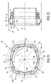
- the configuration of the centering devices 8a and 8b current is shown in Figures 2 and 3.
- the thin-walled tube 3 has an annular portion reinforced 3a, around which is mounted a sheath 9 which has at one end 9a an external thread 10 and at the other end 9b a conical peripheral wall 11 which diverges in the extension thread 10.
- a split elastic ring 12 the inner wall of which is also conical, is slid by the threaded end 9a on the sleeve 9.
- a nut 14 having an internal thread suitable for thread 10 advances the ring 12 on the conical wall 11. This which causes the ring 12 to expand.
- the split elastic ring 12 shown in detail in FIG. 3, presents a peripheral surface with a substantially square section with rounded corners 15 whose curvature is adapted according to the inner diameter of the shaft 2.
- the corners 15 abut against the inner wall of the shaft 2.
- the elastic ring 12 thus has four rigid pads of large radial section, delimited externally by the corners 15, and linked in pairs by smaller ring sections radial.
- the elastic ring 12 has a lateral slot 16 and is like the set of two cantilever beams and having their recess in zone 17 diametrically opposite to slot 16. Along these beams, the values of the moment bending and deflection are variable, the support forces are only therefore not the same for the four support points. It follows that the contact stresses between the elastic ring 12 and the shaft of turbine 2 are also different along the supports.
- the object of the invention is to propose a retention device a tube inside a tree, as mentioned in the introduction, which avoids marking the shaft bore.
- skates have thin cylindrical and elastic walls having at least rest an outside diameter slightly different from the diameter inside the hollow tree and following the inner wall of the tree after assembly.
- the radial section of the pads according to the invention is clearly decreased compared to that of the skates of the prior art.
- This arrangement ensures the distribution of the radial forces, due to the torque of clamping, over a larger area and reduces stresses contact between the pads and the bore of the turbine shaft.
- the ring is a split elastic ring and the means for enabling the expansion of the ring after assembly include a system of male / female cone formed on the sheath and the ring and a nut ensuring by clamping on the sheath the axial displacement of the ring, its radial expansion and the deformation of the thin walls skates.
- the split ring has a substantially inner wall cylindrical and each shoe is connected by its central axial zone to said cylindrical inner wall by means of a radial wall and has a flexible lip on each side of said radial wall.
- the outside diameter of the pads at rest is less than the inside diameter of the tree and increases when assembly.
- the split ring comprises several cylindrical sections alternating with the pads, the ends of each shoe being embedded respectively on the two adjacent cylindrical sections.
- the outside diameter of the pads at rest is also less than the inside diameter of the tree and increases during assembly.
- each skate has a thin cylindrical wall having at rest a outer diameter less than the inner diameter of the shaft, and, at each end of the thin wall, a sector-shaped body, and the bodies are held axially by two elastic rods to form a ring which, at rest, has an inside diameter less than outer diameter of the sheath.
- the sheath has a shoulder for axially retaining the body on a cylindrical portion of sheath, and the bodies have on the shoulder side a chamfer allowing the expansion of the ring and rods when mounting the ring by tightening a nut on the scabbard.
- skates are provided regularly distributed around the axis of rotation of the turbomachine.
- the means for allowing expansion of the ring during assembly have a male / female cone system formed on the sheath and the bodies and a nut ensuring by tightening on the sheath the axial displacement of the bodies, the radial expansion of the bodies and rushes, and the deformation of the thin walls of the skates.
- the circumscribed circle of all the pads has a diameter slightly smaller than the inside diameter of the shaft, to allow the installation of the device in the bore of the turbine shaft before mounting the tube.
- the tube 3 comprises, as in the prior state, a reinforced annular portion, not shown in Figures 4 to 14, around which is mounted a sheath 9 which has a first threaded end 9a and a second end 9b in the extension of the threaded end 9a intended to receive an expandable ring 20.
- the ring 20 is retained on the sleeve 9 by a nut 14 which has an internal thread cooperating with the thread of the end 9a of the sleeve 9.
- the ring 20 is interposed between the sheath 9 and the internal wall 21 of the turbine shaft 2.
- FIGS. 4 to 14 only the internal wall 21 of the turbine shaft 2 is shown for the sake of clarity.
- This internal wall 21 has a radius E / 2 in line with the ring 20 after introduction of the centering device into the bore of the turbine shaft 2 and mounting the tube 3.
- the ring 20 has a slot 22 as in the prior art described in introduction.
- the expandable ring 20 has a substantially cylindrical inner wall 23 which, after mounting, surround the sleeve 9.
- the inner wall 23 extend radially towards the outside in orthogonal planes intersecting along the axis of rotation X of the turbomachine, four radial walls 24 or more which support at their ends thin-walled shoes 25 and cylindrical.
- Each shoe 25 has on each side of the radial wall 24 support, a flexible lip, respectively 26a and 26b.
- each shoe 25 becomes equal to the radius E / 2 of the turbine shaft.
- Each pad 25 is therefore in homogeneous support against the internal wall 21 over its entire surface exterior.
- the ring 20 slides on the end 9b of the sleeve 9 and undergoes a radial expansion towards the exterior, thanks to a male / female cone system formed at the outer periphery of the sleeve end 9b and at the periphery inner ring 20.
- the four pads 25, which bear against the inner wall 21 of the turbine shaft are formed by walls thin cylindrical which, at rest, have an outside radius R2 smaller than the inner radius E / 2 of the turbine shaft.
- the radially inner part of the ring 20 comprises several cylindrical sections 27 circumferentially spaced one on the other and alternating with the pads 25.
- each shoe 25 is embedded respectively on two adjacent sections 27.
- a slot 22 is formed in one of the sections 27.
- This second variant of the centering in the turbine shaft is identical to that of the first variant described above.
- the middle zones 28 of the pads bend when applying a tightening torque using the nut 14 which causes an increase in the radius R2, until that the outer radius of the pads is equal to the radius E / 2 of the shaft of turbine. Then mount the tube 3.
- the bearing surfaces of the pads 25 against the internal wall 21 of the turbine shaft are significantly increased compared to those of the prior art described in the introduction, in which the pads are rigid non-deformable blocks alternating with sections of smaller section connection.
- the elastic ring 20 is constituted by four identical elements 30 independent assembled by means of two elastic ring rings 31.
- Each element 30 has in its middle region a shoe 25 consisting of a thin cylindrical wall whose outer radius R2 is less than the radius E / 2 of the turbine shaft.
- the extremities 25a and 25b of each shoe 25 are embedded respectively on two bodies 31a and 31b which form the lateral parts and radially interior of an element 30.
- the blocks 31a, 31b have the shape of a circle sector.
- Each set 30 is thus in the form of a sector which extends over 90 ° at most.
- the four elements 30 are assembled together by means of two rods 31 which are housed in grooves made on the wall external peripheral of the bodies 31a and 31b, one of the grooves being provided near the front face of the ring 20 and the other near its face back.
- Interstices 32 separate the four elements 30 retained by the rods 31. These interstices 32 widen when the ring 20 is expanded.
- Figure 12 shows an alternative embodiment of the mounting of the ring 20, described above, on the sleeve 9.
- the latter comprises a shoulder 33 which extends radially outwards, against which supports a front face of the ring 20.
- the ring 20 covers a cylindrical portion 34 of sheath, which has a diameter greater than the outside diameter of the threaded end 9a and greater the inside diameter of the ring 20 before mounting on the sleeve 9.
- the bodies 31a and 31b have, on the side of the shoulder 33, a chamfer 35 which allows the expansion of the ring 20 and the rods 31 when the ring rises on the cylindrical part 34 as a result tightening the nut 14.
- the circle circumscribed to four pads 25 has a radius smaller than the inner radius E / 2 of the turbine shaft.
- the central axial zones 28 of the pads 25 will be bent and the outer radius of the pads 25 will be substantially equal to the radius inside E / 2 of the turbine shaft.
- Figure 14 shows another alternative embodiment of the mounting the ring 20 on the sleeve 9.
- the sheath 9 and the bodies 31a and 31b have a male / female cone system which allows the expansion of the ring 20 and of the rods 31 when a tightening torque on nut 14.
- a washer 36 can naturally be interposed between the ring 20 and the nut 14 in all modes or variants of realization described above.
- each expandable ring 20 four pads are provided 25 on each expandable ring 20.
- the number of pads can obviously be different, and preferably this number is even. This what matters above all is that these skates are evenly distributed around the axis of rotation X of the turbine.
- the pads 25 are constituted by walls thin and deformable cylindrical, the bearing surfaces of these skates are relatively high, and the forces are distributed over a large area, without creating prohibitive contact constraints between the centering device and the bore of the turbine shaft. This avoids markings on the turbine shaft.
- the second embodiment of the invention allows a better distribution of forces on all skates, from does symmetry.
Landscapes
- Engineering & Computer Science (AREA)
- Chemical & Material Sciences (AREA)
- Combustion & Propulsion (AREA)
- Mechanical Engineering (AREA)
- General Engineering & Computer Science (AREA)
- Turbine Rotor Nozzle Sealing (AREA)
- Supercharger (AREA)
- Structures Of Non-Positive Displacement Pumps (AREA)
- Ultra Sonic Daignosis Equipment (AREA)
- A Measuring Device Byusing Mechanical Method (AREA)
- Mutual Connection Of Rods And Tubes (AREA)
- Shafts, Cranks, Connecting Bars, And Related Bearings (AREA)
Abstract
Description
et montage du tube 3.
Claims (11)
- Dispositif de centrage d'un tube (3) ou d'une pièce à l'intérieur d'un arbre (2) creux de turbine dans une turbomachine, ce tube (3) ou cette pièce étant solidarisé en rotation audit arbre (2) à ses extrémités, ce dispositif comportant un fourreau (9) solidaire dudit tube (3) ou de ladite pièce et entourant ce dernier, un anneau élastique (20) interposé entre le fourreau (9) et l'arbre (2) et présentant des paires de patins qui s'étendent radialement vers l'extérieur, et des moyens pour permettre l'expansion de l'anneau (20) après l'assemblage du dispositif afin que lesdits patins soient en appui contre la paroi intérieure de l'arbre,
caractérisé par le fait que les patins sont constitués par des parois minces (25) cylindriques et élastiques ayant au repos un diamètre extérieur légèrement différent du diamètre intérieur de l'arbre (2) creux et épousant la paroi interne (21) de l'arbre (2) après assemblage. - Dispositif selon la revendication 1, caractérisé par le fait que l'anneau (20) est un anneau élastique fendu et les moyens pour permettre l'expansion de l'anneau (20) après assemblage comportent un système de cône mâle/femelle formé sur le fourreau (9) et l'anneau (20) et un écrou (14) assurant par serrage sur le fourreau (9) le déplacement axial de l'anneau (20), son expansion radiale, et la déformation des parois minces des patins.
- Dispositif selon la revendication 2, caractérisé par le fait que l'anneau (20) comporte une paroi intérieure (23) sensiblement cylindrique et chaque patin est relié par sa zone axiale médiane à ladite paroi intérieure (23) cylindrique par une paroi radiale (24) et présente une lèvre flexible (26a, 26b) de chaque côté de ladite paroi radiale (24).
- Dispositif selon la revendication 3, caractérisé par le fait que le diamètre extérieur des patins (25) au repos est supérieur au diamètre intérieur de l'arbre (2) et décroít lors de l'assemblage.
- Dispositif selon la revendication 2, caractérisé par le fait que l'anneau (20) comporte plusieurs tronçons (27) cylindriques alternant avec les patins (25), les extrémités (25a, 25b) de chaque patin (25) étant encastrées respectivement sur les deux tronçons (27) cylindriques adjacents.
- Dispositif selon la revendication 5, caractérisé par le fait que le diamètre extérieur des patins (25) au repos est inférieur au diamètre intérieur de l'arbre (2) et croít lors de l'assemblage.
- Dispositif selon la revendication 1, caractérisé par le fait que chaque patin (25) comporte une paroi mince cylindrique ayant au repos un diamètre extérieur inférieur au diamètre intérieur de l'arbre (2), et, à chaque extrémité de ladite paroi mince, un corps (31a, 31b) en forme de secteur, et par le fait que lesdits corps (31a, 31b) sont retenus axialement par deux joncs élastiques (31) pour former un anneau (20) qui, au repos, a un diamètre intérieur inférieur au diamètre extérieur du fourreau (9).
- Dispositif selon la revendication 7, caractérisé par le fait que le fourreau (9) comporte un épaulement (33) pour retenir axialement les corps (31a, 31b) sur une portion cylindrique (34) de fourreau (9), lesdits corps (31a, 31b) présentant du côté de l'épaulement (33) un chanfrein (35) permettant l'expansion de l'anneau (20) et des joncs (31) lors du montage de l'anneau (20) par serrage d'un écrou (14) sur le fourreau (9).
- Dispositif selon la revendication 7, caractérisé par le fait que les moyens pour permettre l'expansion de l'anneau (20) lors du montage comportent un système de cône mâle/femelle formé sur le fourreau (9) et les corps (31a, 31b) et un écrou (14) assurant par serrage sur le fourreau (9) le déplacement axial des corps (31a, 31b), l'expansion radiale des corps (31a, 31b) et des joncs (31) , et la déformation des parois minces des patins (25).
- Dispositif selon l'une des revendications 1 à 9, caractérisé par le fait qu'au repos le cercle circonscrit de l'ensemble des patins (25) a un diamètre légèrement inférieur au diamètre intérieur de l'arbre (2).
- Dispositif selon l'une quelconque des revendications 1 à 10, caractérisé par le fait qu'il comporte quatre patins (25) régulièrement répartis autour de l'axe de rotation (X) de la turbomachine.
Applications Claiming Priority (2)
| Application Number | Priority Date | Filing Date | Title |
|---|---|---|---|
| FR0015473A FR2817289B1 (fr) | 2000-11-30 | 2000-11-30 | Dispositif de centrage d'un tube dans un arbre de turbine |
| FR0015473 | 2000-11-30 |
Publications (2)
| Publication Number | Publication Date |
|---|---|
| EP1225322A1 true EP1225322A1 (fr) | 2002-07-24 |
| EP1225322B1 EP1225322B1 (fr) | 2006-02-01 |
Family
ID=8857050
Family Applications (1)
| Application Number | Title | Priority Date | Filing Date |
|---|---|---|---|
| EP01403059A Expired - Lifetime EP1225322B1 (fr) | 2000-11-30 | 2001-11-29 | Dispositif de centrage d'un tube dans un arbre de turbine |
Country Status (11)
| Country | Link |
|---|---|
| US (1) | US7004725B2 (fr) |
| EP (1) | EP1225322B1 (fr) |
| JP (1) | JP4043944B2 (fr) |
| CN (1) | CN1250868C (fr) |
| AT (1) | ATE317060T1 (fr) |
| CA (1) | CA2430285C (fr) |
| DE (1) | DE60116987T2 (fr) |
| ES (1) | ES2253342T3 (fr) |
| FR (1) | FR2817289B1 (fr) |
| RU (1) | RU2249702C2 (fr) |
| WO (1) | WO2002044538A2 (fr) |
Families Citing this family (21)
| Publication number | Priority date | Publication date | Assignee | Title |
|---|---|---|---|---|
| FR2872218B1 (fr) * | 2004-06-29 | 2006-09-29 | Snecma Moteurs Sa | Tube de degazage pour arbre basse-pression de turbomachine |
| US7197877B2 (en) * | 2004-08-04 | 2007-04-03 | Siemens Power Generation, Inc. | Support system for a pilot nozzle of a turbine engine |
| FR2888897B1 (fr) * | 2005-07-21 | 2007-10-19 | Snecma | Dispositif d'amortissement des vibrations d'un anneau de retention axiale des aubes de soufflante d'une turbomachine |
| GB0701609D0 (en) | 2007-01-29 | 2007-03-07 | Boc Group Plc | Vacuum pump |
| EP1970532A1 (fr) * | 2007-03-12 | 2008-09-17 | Siemens Aktiengesellschaft | Rotor d'une turbomachine thermique tout comme turbine à gaz |
| EP1970533A1 (fr) * | 2007-03-12 | 2008-09-17 | Siemens Aktiengesellschaft | Turbine ayant au moins un rotor comprenant des disques rotoriques et un tirant |
| FR2926604B1 (fr) * | 2008-01-23 | 2010-03-26 | Snecma | Centrage d'une piece a l'interieur d'un arbre de rotor dans une turbomachine |
| US8215919B2 (en) * | 2008-02-22 | 2012-07-10 | Hamilton Sundstrand Corporation | Curved tooth coupling for a miniature gas turbine engine |
| CN103109044B (zh) * | 2010-03-26 | 2016-02-24 | 斯奈克玛 | 涡轮喷气式发动机通风管、安装该通风管的方法以及设置有该通风管的涡轮喷气式发动机 |
| CN102005855B (zh) * | 2010-12-16 | 2012-11-14 | 中国人民解放军91872部队 | 中空轴电机 |
| CN102720542B (zh) * | 2012-06-11 | 2014-09-03 | 东方电气集团东方汽轮机有限公司 | 一种汽轮机转子 |
| FR2997996B1 (fr) | 2012-11-12 | 2015-01-09 | Snecma | Support de tube d'evacuation d'air dans une turbomachine |
| FR3008135B1 (fr) * | 2013-07-08 | 2017-05-26 | Snecma | Centrage d'une piece a l'interieur d'un arbre de rotor dans une turbomachine |
| KR101509382B1 (ko) * | 2014-01-15 | 2015-04-07 | 두산중공업 주식회사 | 댐핑 클램프를 구비한 가스 터빈 |
| JP6183564B2 (ja) * | 2014-11-14 | 2017-08-23 | 株式会社Ihi | ジェットエンジン |
| JP6455179B2 (ja) | 2015-01-26 | 2019-01-23 | 株式会社Ihi | センターベントチューブ調芯機構及びセンターベントチューブ支持装置 |
| FR3058480B1 (fr) * | 2016-11-07 | 2018-12-07 | Safran Aircraft Engines | Support assurant une liaison complete entre un arbre turbine et un tube de degazage d'un turboreacteur |
| US11162457B2 (en) * | 2017-08-11 | 2021-11-02 | General Electric Company | Turbine fan system and method |
| WO2019069769A1 (fr) * | 2017-10-02 | 2019-04-11 | 株式会社Ihi | Dispositif de support de tube d'évent central pour moteur turbo à double flux |
| FR3094031B1 (fr) * | 2019-03-18 | 2021-05-14 | Safran Aircraft Engines | Ensemble pour une turbomachine |
| FR3126459A1 (fr) * | 2021-08-31 | 2023-03-03 | Safran Aircraft Engines | Turboréacteur d’aéronef comprenant un arbre de turboréacteur et un raidisseur d’arbre. |
Citations (3)
| Publication number | Priority date | Publication date | Assignee | Title |
|---|---|---|---|---|
| US4872767A (en) * | 1985-04-03 | 1989-10-10 | General Electric Company | Bearing support |
| US5073036A (en) * | 1990-03-30 | 1991-12-17 | Rockwell International Corporation | Hydrostatic bearing for axial/radial support |
| US5603574A (en) * | 1987-05-29 | 1997-02-18 | Kmc, Inc. | Fluid dampened support having variable stiffness and damping |
Family Cites Families (4)
| Publication number | Priority date | Publication date | Assignee | Title |
|---|---|---|---|---|
| US2222494A (en) * | 1938-12-14 | 1940-11-19 | Scovill Manufacturing Co | Slotted spider member |
| US2554368A (en) * | 1944-08-23 | 1951-05-22 | United Aircraft Corp | Turbine rotor cooling |
| US3556676A (en) * | 1968-08-28 | 1971-01-19 | Igor Konstantinovich Gorbunov | Liquid-cooling system of gas turbine rotors |
| DE19757945B4 (de) * | 1997-12-27 | 2006-11-30 | Alstom | Rotor für thermische Turbomaschine |
-
2000
- 2000-11-30 FR FR0015473A patent/FR2817289B1/fr not_active Expired - Fee Related
-
2001
- 2001-11-29 RU RU2003119157/06A patent/RU2249702C2/ru not_active IP Right Cessation
- 2001-11-29 CA CA002430285A patent/CA2430285C/fr not_active Expired - Fee Related
- 2001-11-29 EP EP01403059A patent/EP1225322B1/fr not_active Expired - Lifetime
- 2001-11-29 CN CN01804011.XA patent/CN1250868C/zh not_active Expired - Fee Related
- 2001-11-29 WO PCT/FR2001/003754 patent/WO2002044538A2/fr active Application Filing
- 2001-11-29 AT AT01403059T patent/ATE317060T1/de not_active IP Right Cessation
- 2001-11-29 JP JP2002546873A patent/JP4043944B2/ja not_active Expired - Fee Related
- 2001-11-29 ES ES01403059T patent/ES2253342T3/es not_active Expired - Lifetime
- 2001-11-29 DE DE60116987T patent/DE60116987T2/de not_active Expired - Lifetime
- 2001-11-29 US US10/416,161 patent/US7004725B2/en not_active Expired - Lifetime
Patent Citations (3)
| Publication number | Priority date | Publication date | Assignee | Title |
|---|---|---|---|---|
| US4872767A (en) * | 1985-04-03 | 1989-10-10 | General Electric Company | Bearing support |
| US5603574A (en) * | 1987-05-29 | 1997-02-18 | Kmc, Inc. | Fluid dampened support having variable stiffness and damping |
| US5073036A (en) * | 1990-03-30 | 1991-12-17 | Rockwell International Corporation | Hydrostatic bearing for axial/radial support |
Also Published As
| Publication number | Publication date |
|---|---|
| ATE317060T1 (de) | 2006-02-15 |
| CN1395649A (zh) | 2003-02-05 |
| ES2253342T3 (es) | 2006-06-01 |
| JP2004514841A (ja) | 2004-05-20 |
| DE60116987T2 (de) | 2006-09-21 |
| CA2430285A1 (fr) | 2002-06-06 |
| WO2002044538A2 (fr) | 2002-06-06 |
| FR2817289B1 (fr) | 2003-01-31 |
| DE60116987D1 (de) | 2006-04-13 |
| JP4043944B2 (ja) | 2008-02-06 |
| EP1225322B1 (fr) | 2006-02-01 |
| US7004725B2 (en) | 2006-02-28 |
| WO2002044538A3 (fr) | 2002-08-01 |
| CA2430285C (fr) | 2008-10-07 |
| US20040025494A1 (en) | 2004-02-12 |
| RU2249702C2 (ru) | 2005-04-10 |
| CN1250868C (zh) | 2006-04-12 |
| FR2817289A1 (fr) | 2002-05-31 |
Similar Documents
| Publication | Publication Date | Title |
|---|---|---|
| CA2430285C (fr) | Dispositif de centrage d'un tube dans un arbre de turbine | |
| EP1180580B1 (fr) | Dispositif de rétention d'une flasque annulaire contre une face radiale d'un disque à aubes | |
| EP1498624B1 (fr) | Dispositif perfectionné de fixation d'un arbre de moteur sur un support de palier | |
| EP2878873B1 (fr) | Dispositif de raccordement rapide de type cartouche | |
| EP2433044A1 (fr) | Dispositif de raccordement rapide pour circuits de fluide pouvant subir d'importantes variations de pression | |
| EP2923858A1 (fr) | Roue d'aéronef comportant un canal organisant un chemin de fuite dans la roue | |
| EP1807648A1 (fr) | Jonc de verrouillage segmente, assemblage et procede de montage correspondants | |
| WO2001094798A1 (fr) | Insert d'implantation d'un raccord de tube dans un logement taraude | |
| EP2480379B1 (fr) | Outil de prehension | |
| WO2014037547A2 (fr) | Joint circulaire d'etancheite a brosse | |
| FR2883802A1 (fr) | Anneau de verrouillage dans un ensemble de montage d'un pneumatique sur un moyeu de vehicule | |
| CA2603311C (fr) | Systeme de verrouillage d'un anneau de montage sur un moyeu de vehicule | |
| EP1855011B1 (fr) | Ensemble pour compresseur de moteur d'aéronef comprenant des aubes à attache marteau à pied incliné | |
| FR2743613A1 (fr) | Entretoise pour le soudage d'un tube a un raccord | |
| EP1294320A1 (fr) | Prothese articulee | |
| EP2320432B1 (fr) | Emballage pour le transport et/ou entreposage de matières radioactives conferant un transfert thermique renforce | |
| FR2759158A1 (fr) | Charge generatrice de noyau comportant des moyens de liaison du revetement et de l'enveloppe | |
| FR2741142A1 (fr) | Charge generatrice de noyau ayant une tenue a l'acceleration amelioree | |
| BE1012055A3 (fr) | Dispositif de fixation par ecrou. | |
| FR2900698A1 (fr) | Cheville de fixation d'un clou destine a etre fixe au sol, notamment d'un clou podotactile, et ensemble comprenant cette vheville et ce clou | |
| FR2869965A1 (fr) | Ensemble de roulement et joint homocinetique correspondant | |
| FR2877994A1 (fr) | Support de palier, et moteur d'aeronef equipe d'un tel support de palier. | |
| EP3623101A1 (fr) | Outil de centrage d'alésages et procédé de centrage des alésages d'une attache-moteur d'un aéronef utilisant un outil de centrage | |
| FR2766732A1 (fr) | Outil d'extraction d'un roulement, notamment pour roue de patin a roues en ligne | |
| FR2816515A1 (fr) | Baton telescopique de ski, randonnee ou autre |
Legal Events
| Date | Code | Title | Description |
|---|---|---|---|
| PUAI | Public reference made under article 153(3) epc to a published international application that has entered the european phase |
Free format text: ORIGINAL CODE: 0009012 |
|
| 17P | Request for examination filed |
Effective date: 20011206 |
|
| AK | Designated contracting states |
Kind code of ref document: A1 Designated state(s): AT BE CH CY DE DK ES FI FR GB GR IE IT LI LU MC NL PT SE TR |
|
| AX | Request for extension of the european patent |
Free format text: AL;LT;LV;MK;RO;SI |
|
| AKX | Designation fees paid |
Designated state(s): AT BE CH CY DE DK ES FI FR GB GR IE IT LI LU MC NL PT SE TR |
|
| 17Q | First examination report despatched |
Effective date: 20041124 |
|
| GRAP | Despatch of communication of intention to grant a patent |
Free format text: ORIGINAL CODE: EPIDOSNIGR1 |
|
| GRAS | Grant fee paid |
Free format text: ORIGINAL CODE: EPIDOSNIGR3 |
|
| RAP1 | Party data changed (applicant data changed or rights of an application transferred) |
Owner name: SNECMA |
|
| GRAA | (expected) grant |
Free format text: ORIGINAL CODE: 0009210 |
|
| AK | Designated contracting states |
Kind code of ref document: B1 Designated state(s): AT BE CH CY DE DK ES FI FR GB GR IE IT LI LU MC NL PT SE TR |
|
| PG25 | Lapsed in a contracting state [announced via postgrant information from national office to epo] |
Ref country code: IT Free format text: LAPSE BECAUSE OF FAILURE TO SUBMIT A TRANSLATION OF THE DESCRIPTION OR TO PAY THE FEE WITHIN THE PRESCRIBED TIME-LIMIT;WARNING: LAPSES OF ITALIAN PATENTS WITH EFFECTIVE DATE BEFORE 2007 MAY HAVE OCCURRED AT ANY TIME BEFORE 2007. THE CORRECT EFFECTIVE DATE MAY BE DIFFERENT FROM THE ONE RECORDED. Effective date: 20060201 Ref country code: NL Free format text: LAPSE BECAUSE OF FAILURE TO SUBMIT A TRANSLATION OF THE DESCRIPTION OR TO PAY THE FEE WITHIN THE PRESCRIBED TIME-LIMIT Effective date: 20060201 Ref country code: IE Free format text: LAPSE BECAUSE OF FAILURE TO SUBMIT A TRANSLATION OF THE DESCRIPTION OR TO PAY THE FEE WITHIN THE PRESCRIBED TIME-LIMIT Effective date: 20060201 Ref country code: AT Free format text: LAPSE BECAUSE OF FAILURE TO SUBMIT A TRANSLATION OF THE DESCRIPTION OR TO PAY THE FEE WITHIN THE PRESCRIBED TIME-LIMIT Effective date: 20060201 Ref country code: FI Free format text: LAPSE BECAUSE OF FAILURE TO SUBMIT A TRANSLATION OF THE DESCRIPTION OR TO PAY THE FEE WITHIN THE PRESCRIBED TIME-LIMIT Effective date: 20060201 |
|
| REG | Reference to a national code |
Ref country code: GB Ref legal event code: FG4D Free format text: NOT ENGLISH |
|
| REG | Reference to a national code |
Ref country code: CH Ref legal event code: EP |
|
| GBT | Gb: translation of ep patent filed (gb section 77(6)(a)/1977) |
Effective date: 20060201 |
|
| REG | Reference to a national code |
Ref country code: SE Ref legal event code: TRGR |
|
| REG | Reference to a national code |
Ref country code: IE Ref legal event code: FG4D Free format text: LANGUAGE OF EP DOCUMENT: FRENCH |
|
| REF | Corresponds to: |
Ref document number: 60116987 Country of ref document: DE Date of ref document: 20060413 Kind code of ref document: P |
|
| PG25 | Lapsed in a contracting state [announced via postgrant information from national office to epo] |
Ref country code: DK Free format text: LAPSE BECAUSE OF FAILURE TO SUBMIT A TRANSLATION OF THE DESCRIPTION OR TO PAY THE FEE WITHIN THE PRESCRIBED TIME-LIMIT Effective date: 20060501 |
|
| REG | Reference to a national code |
Ref country code: ES Ref legal event code: FG2A Ref document number: 2253342 Country of ref document: ES Kind code of ref document: T3 |
|
| NLV1 | Nl: lapsed or annulled due to failure to fulfill the requirements of art. 29p and 29m of the patents act | ||
| PG25 | Lapsed in a contracting state [announced via postgrant information from national office to epo] |
Ref country code: PT Free format text: LAPSE BECAUSE OF FAILURE TO SUBMIT A TRANSLATION OF THE DESCRIPTION OR TO PAY THE FEE WITHIN THE PRESCRIBED TIME-LIMIT Effective date: 20060703 |
|
| REG | Reference to a national code |
Ref country code: IE Ref legal event code: FD4D |
|
| PG25 | Lapsed in a contracting state [announced via postgrant information from national office to epo] |
Ref country code: CH Free format text: LAPSE BECAUSE OF NON-PAYMENT OF DUE FEES Effective date: 20061130 Ref country code: MC Free format text: LAPSE BECAUSE OF NON-PAYMENT OF DUE FEES Effective date: 20061130 Ref country code: LI Free format text: LAPSE BECAUSE OF NON-PAYMENT OF DUE FEES Effective date: 20061130 |
|
| PLBE | No opposition filed within time limit |
Free format text: ORIGINAL CODE: 0009261 |
|
| STAA | Information on the status of an ep patent application or granted ep patent |
Free format text: STATUS: NO OPPOSITION FILED WITHIN TIME LIMIT |
|
| 26N | No opposition filed |
Effective date: 20061103 |
|
| REG | Reference to a national code |
Ref country code: CH Ref legal event code: PL |
|
| PG25 | Lapsed in a contracting state [announced via postgrant information from national office to epo] |
Ref country code: GR Free format text: LAPSE BECAUSE OF FAILURE TO SUBMIT A TRANSLATION OF THE DESCRIPTION OR TO PAY THE FEE WITHIN THE PRESCRIBED TIME-LIMIT Effective date: 20060502 |
|
| PG25 | Lapsed in a contracting state [announced via postgrant information from national office to epo] |
Ref country code: TR Free format text: LAPSE BECAUSE OF FAILURE TO SUBMIT A TRANSLATION OF THE DESCRIPTION OR TO PAY THE FEE WITHIN THE PRESCRIBED TIME-LIMIT Effective date: 20060201 Ref country code: LU Free format text: LAPSE BECAUSE OF NON-PAYMENT OF DUE FEES Effective date: 20061129 |
|
| PG25 | Lapsed in a contracting state [announced via postgrant information from national office to epo] |
Ref country code: CY Free format text: LAPSE BECAUSE OF FAILURE TO SUBMIT A TRANSLATION OF THE DESCRIPTION OR TO PAY THE FEE WITHIN THE PRESCRIBED TIME-LIMIT Effective date: 20060201 |
|
| PGFP | Annual fee paid to national office [announced via postgrant information from national office to epo] |
Ref country code: ES Payment date: 20121114 Year of fee payment: 12 |
|
| REG | Reference to a national code |
Ref country code: ES Ref legal event code: FD2A Effective date: 20150331 |
|
| PG25 | Lapsed in a contracting state [announced via postgrant information from national office to epo] |
Ref country code: ES Free format text: LAPSE BECAUSE OF NON-PAYMENT OF DUE FEES Effective date: 20131130 |
|
| REG | Reference to a national code |
Ref country code: FR Ref legal event code: PLFP Year of fee payment: 15 |
|
| REG | Reference to a national code |
Ref country code: FR Ref legal event code: PLFP Year of fee payment: 16 |
|
| PGFP | Annual fee paid to national office [announced via postgrant information from national office to epo] |
Ref country code: DE Payment date: 20161020 Year of fee payment: 16 Ref country code: GB Payment date: 20161027 Year of fee payment: 16 |
|
| PGFP | Annual fee paid to national office [announced via postgrant information from national office to epo] |
Ref country code: IT Payment date: 20161025 Year of fee payment: 16 Ref country code: BE Payment date: 20161024 Year of fee payment: 16 Ref country code: SE Payment date: 20161024 Year of fee payment: 16 |
|
| REG | Reference to a national code |
Ref country code: FR Ref legal event code: PLFP Year of fee payment: 17 |
|
| REG | Reference to a national code |
Ref country code: FR Ref legal event code: CD Owner name: SAFRAN AIRCRAFT ENGINES Effective date: 20170713 |
|
| REG | Reference to a national code |
Ref country code: DE Ref legal event code: R119 Ref document number: 60116987 Country of ref document: DE |
|
| REG | Reference to a national code |
Ref country code: SE Ref legal event code: EUG |
|
| GBPC | Gb: european patent ceased through non-payment of renewal fee |
Effective date: 20171129 |
|
| PG25 | Lapsed in a contracting state [announced via postgrant information from national office to epo] |
Ref country code: SE Free format text: LAPSE BECAUSE OF NON-PAYMENT OF DUE FEES Effective date: 20171130 |
|
| REG | Reference to a national code |
Ref country code: BE Ref legal event code: MM Effective date: 20171130 |
|
| REG | Reference to a national code |
Ref country code: FR Ref legal event code: PLFP Year of fee payment: 18 |
|
| PG25 | Lapsed in a contracting state [announced via postgrant information from national office to epo] |
Ref country code: DE Free format text: LAPSE BECAUSE OF NON-PAYMENT OF DUE FEES Effective date: 20180602 Ref country code: IT Free format text: LAPSE BECAUSE OF NON-PAYMENT OF DUE FEES Effective date: 20171129 |
|
| PG25 | Lapsed in a contracting state [announced via postgrant information from national office to epo] |
Ref country code: BE Free format text: LAPSE BECAUSE OF NON-PAYMENT OF DUE FEES Effective date: 20171130 Ref country code: GB Free format text: LAPSE BECAUSE OF NON-PAYMENT OF DUE FEES Effective date: 20171129 |
|
| PGFP | Annual fee paid to national office [announced via postgrant information from national office to epo] |
Ref country code: FR Payment date: 20201021 Year of fee payment: 20 |