EP1225296B1 - Torantriebsdrehmomentübertragungsvorrichtung, damit versehene motorische Torantriebsvorrichtung sowie damit versehenes Tor - Google Patents
Torantriebsdrehmomentübertragungsvorrichtung, damit versehene motorische Torantriebsvorrichtung sowie damit versehenes Tor Download PDFInfo
- Publication number
- EP1225296B1 EP1225296B1 EP01111691A EP01111691A EP1225296B1 EP 1225296 B1 EP1225296 B1 EP 1225296B1 EP 01111691 A EP01111691 A EP 01111691A EP 01111691 A EP01111691 A EP 01111691A EP 1225296 B1 EP1225296 B1 EP 1225296B1
- Authority
- EP
- European Patent Office
- Prior art keywords
- door
- torque transmission
- drive torque
- door drive
- shaft
- Prior art date
- Legal status (The legal status is an assumption and is not a legal conclusion. Google has not performed a legal analysis and makes no representation as to the accuracy of the status listed.)
- Expired - Lifetime
Links
Images


Classifications
-
- E—FIXED CONSTRUCTIONS
- E06—DOORS, WINDOWS, SHUTTERS, OR ROLLER BLINDS IN GENERAL; LADDERS
- E06B—FIXED OR MOVABLE CLOSURES FOR OPENINGS IN BUILDINGS, VEHICLES, FENCES OR LIKE ENCLOSURES IN GENERAL, e.g. DOORS, WINDOWS, BLINDS, GATES
- E06B9/00—Screening or protective devices for wall or similar openings, with or without operating or securing mechanisms; Closures of similar construction
- E06B9/56—Operating, guiding or securing devices or arrangements for roll-type closures; Spring drums; Tape drums; Counterweighting arrangements therefor
- E06B9/68—Operating devices or mechanisms, e.g. with electric drive
- E06B9/70—Operating devices or mechanisms, e.g. with electric drive comprising an electric motor positioned outside the roller
-
- E—FIXED CONSTRUCTIONS
- E05—LOCKS; KEYS; WINDOW OR DOOR FITTINGS; SAFES
- E05F—DEVICES FOR MOVING WINGS INTO OPEN OR CLOSED POSITION; CHECKS FOR WINGS; WING FITTINGS NOT OTHERWISE PROVIDED FOR, CONCERNED WITH THE FUNCTIONING OF THE WING
- E05F15/00—Power-operated mechanisms for wings
- E05F15/60—Power-operated mechanisms for wings using electrical actuators
- E05F15/603—Power-operated mechanisms for wings using electrical actuators using rotary electromotors
-
- E—FIXED CONSTRUCTIONS
- E05—LOCKS; KEYS; WINDOW OR DOOR FITTINGS; SAFES
- E05F—DEVICES FOR MOVING WINGS INTO OPEN OR CLOSED POSITION; CHECKS FOR WINGS; WING FITTINGS NOT OTHERWISE PROVIDED FOR, CONCERNED WITH THE FUNCTIONING OF THE WING
- E05F15/00—Power-operated mechanisms for wings
- E05F15/60—Power-operated mechanisms for wings using electrical actuators
- E05F15/603—Power-operated mechanisms for wings using electrical actuators using rotary electromotors
- E05F15/665—Power-operated mechanisms for wings using electrical actuators using rotary electromotors for vertically-sliding wings
- E05F15/668—Power-operated mechanisms for wings using electrical actuators using rotary electromotors for vertically-sliding wings for overhead wings
- E05F15/681—Power-operated mechanisms for wings using electrical actuators using rotary electromotors for vertically-sliding wings for overhead wings operated by flexible elongated pulling elements, e.g. belts
- E05F15/686—Power-operated mechanisms for wings using electrical actuators using rotary electromotors for vertically-sliding wings for overhead wings operated by flexible elongated pulling elements, e.g. belts by cables or ropes
-
- E—FIXED CONSTRUCTIONS
- E05—LOCKS; KEYS; WINDOW OR DOOR FITTINGS; SAFES
- E05F—DEVICES FOR MOVING WINGS INTO OPEN OR CLOSED POSITION; CHECKS FOR WINGS; WING FITTINGS NOT OTHERWISE PROVIDED FOR, CONCERNED WITH THE FUNCTIONING OF THE WING
- E05F5/00—Braking devices, e.g. checks; Stops; Buffers
-
- E—FIXED CONSTRUCTIONS
- E05—LOCKS; KEYS; WINDOW OR DOOR FITTINGS; SAFES
- E05D—HINGES OR SUSPENSION DEVICES FOR DOORS, WINDOWS OR WINGS
- E05D13/00—Accessories for sliding or lifting wings, e.g. pulleys, safety catches
- E05D13/10—Counterbalance devices
- E05D13/12—Counterbalance devices with springs
- E05D13/1253—Counterbalance devices with springs with canted-coil torsion springs
- E05D13/1261—Counterbalance devices with springs with canted-coil torsion springs specially adapted for overhead wings
-
- E—FIXED CONSTRUCTIONS
- E05—LOCKS; KEYS; WINDOW OR DOOR FITTINGS; SAFES
- E05D—HINGES OR SUSPENSION DEVICES FOR DOORS, WINDOWS OR WINGS
- E05D15/00—Suspension arrangements for wings
- E05D15/16—Suspension arrangements for wings for wings sliding vertically more or less in their own plane
- E05D15/24—Suspension arrangements for wings for wings sliding vertically more or less in their own plane consisting of parts connected at their edges
-
- E—FIXED CONSTRUCTIONS
- E05—LOCKS; KEYS; WINDOW OR DOOR FITTINGS; SAFES
- E05D—HINGES OR SUSPENSION DEVICES FOR DOORS, WINDOWS OR WINGS
- E05D15/00—Suspension arrangements for wings
- E05D15/26—Suspension arrangements for wings for folding wings
-
- E—FIXED CONSTRUCTIONS
- E05—LOCKS; KEYS; WINDOW OR DOOR FITTINGS; SAFES
- E05F—DEVICES FOR MOVING WINGS INTO OPEN OR CLOSED POSITION; CHECKS FOR WINGS; WING FITTINGS NOT OTHERWISE PROVIDED FOR, CONCERNED WITH THE FUNCTIONING OF THE WING
- E05F15/00—Power-operated mechanisms for wings
- E05F15/60—Power-operated mechanisms for wings using electrical actuators
- E05F15/603—Power-operated mechanisms for wings using electrical actuators using rotary electromotors
- E05F15/665—Power-operated mechanisms for wings using electrical actuators using rotary electromotors for vertically-sliding wings
- E05F15/668—Power-operated mechanisms for wings using electrical actuators using rotary electromotors for vertically-sliding wings for overhead wings
- E05F15/681—Power-operated mechanisms for wings using electrical actuators using rotary electromotors for vertically-sliding wings for overhead wings operated by flexible elongated pulling elements, e.g. belts
- E05F15/684—Power-operated mechanisms for wings using electrical actuators using rotary electromotors for vertically-sliding wings for overhead wings operated by flexible elongated pulling elements, e.g. belts by chains
-
- E—FIXED CONSTRUCTIONS
- E05—LOCKS; KEYS; WINDOW OR DOOR FITTINGS; SAFES
- E05Y—INDEXING SCHEME ASSOCIATED WITH SUBCLASSES E05D AND E05F, RELATING TO CONSTRUCTION ELEMENTS, ELECTRIC CONTROL, POWER SUPPLY, POWER SIGNAL OR TRANSMISSION, USER INTERFACES, MOUNTING OR COUPLING, DETAILS, ACCESSORIES, AUXILIARY OPERATIONS NOT OTHERWISE PROVIDED FOR, APPLICATION THEREOF
- E05Y2201/00—Constructional elements; Accessories therefor
- E05Y2201/40—Motors; Magnets; Springs; Weights; Accessories therefor
- E05Y2201/47—Springs
-
- E—FIXED CONSTRUCTIONS
- E05—LOCKS; KEYS; WINDOW OR DOOR FITTINGS; SAFES
- E05Y—INDEXING SCHEME ASSOCIATED WITH SUBCLASSES E05D AND E05F, RELATING TO CONSTRUCTION ELEMENTS, ELECTRIC CONTROL, POWER SUPPLY, POWER SIGNAL OR TRANSMISSION, USER INTERFACES, MOUNTING OR COUPLING, DETAILS, ACCESSORIES, AUXILIARY OPERATIONS NOT OTHERWISE PROVIDED FOR, APPLICATION THEREOF
- E05Y2201/00—Constructional elements; Accessories therefor
- E05Y2201/40—Motors; Magnets; Springs; Weights; Accessories therefor
- E05Y2201/47—Springs
- E05Y2201/488—Traction springs
-
- E—FIXED CONSTRUCTIONS
- E05—LOCKS; KEYS; WINDOW OR DOOR FITTINGS; SAFES
- E05Y—INDEXING SCHEME ASSOCIATED WITH SUBCLASSES E05D AND E05F, RELATING TO CONSTRUCTION ELEMENTS, ELECTRIC CONTROL, POWER SUPPLY, POWER SIGNAL OR TRANSMISSION, USER INTERFACES, MOUNTING OR COUPLING, DETAILS, ACCESSORIES, AUXILIARY OPERATIONS NOT OTHERWISE PROVIDED FOR, APPLICATION THEREOF
- E05Y2201/00—Constructional elements; Accessories therefor
- E05Y2201/60—Suspension or transmission members; Accessories therefor
- E05Y2201/622—Suspension or transmission members elements
- E05Y2201/644—Flexible elongated pulling elements
- E05Y2201/646—Flexible elongated pulling elements continuous, e.g. closed loops
-
- E—FIXED CONSTRUCTIONS
- E05—LOCKS; KEYS; WINDOW OR DOOR FITTINGS; SAFES
- E05Y—INDEXING SCHEME ASSOCIATED WITH SUBCLASSES E05D AND E05F, RELATING TO CONSTRUCTION ELEMENTS, ELECTRIC CONTROL, POWER SUPPLY, POWER SIGNAL OR TRANSMISSION, USER INTERFACES, MOUNTING OR COUPLING, DETAILS, ACCESSORIES, AUXILIARY OPERATIONS NOT OTHERWISE PROVIDED FOR, APPLICATION THEREOF
- E05Y2201/00—Constructional elements; Accessories therefor
- E05Y2201/60—Suspension or transmission members; Accessories therefor
- E05Y2201/622—Suspension or transmission members elements
- E05Y2201/644—Flexible elongated pulling elements
- E05Y2201/654—Cables
-
- E—FIXED CONSTRUCTIONS
- E05—LOCKS; KEYS; WINDOW OR DOOR FITTINGS; SAFES
- E05Y—INDEXING SCHEME ASSOCIATED WITH SUBCLASSES E05D AND E05F, RELATING TO CONSTRUCTION ELEMENTS, ELECTRIC CONTROL, POWER SUPPLY, POWER SIGNAL OR TRANSMISSION, USER INTERFACES, MOUNTING OR COUPLING, DETAILS, ACCESSORIES, AUXILIARY OPERATIONS NOT OTHERWISE PROVIDED FOR, APPLICATION THEREOF
- E05Y2201/00—Constructional elements; Accessories therefor
- E05Y2201/60—Suspension or transmission members; Accessories therefor
- E05Y2201/622—Suspension or transmission members elements
- E05Y2201/644—Flexible elongated pulling elements
- E05Y2201/656—Chains
-
- E—FIXED CONSTRUCTIONS
- E05—LOCKS; KEYS; WINDOW OR DOOR FITTINGS; SAFES
- E05Y—INDEXING SCHEME ASSOCIATED WITH SUBCLASSES E05D AND E05F, RELATING TO CONSTRUCTION ELEMENTS, ELECTRIC CONTROL, POWER SUPPLY, POWER SIGNAL OR TRANSMISSION, USER INTERFACES, MOUNTING OR COUPLING, DETAILS, ACCESSORIES, AUXILIARY OPERATIONS NOT OTHERWISE PROVIDED FOR, APPLICATION THEREOF
- E05Y2201/00—Constructional elements; Accessories therefor
- E05Y2201/60—Suspension or transmission members; Accessories therefor
- E05Y2201/622—Suspension or transmission members elements
- E05Y2201/658—Members cooperating with flexible elongated pulling elements
- E05Y2201/66—Deflectors; Guides
-
- E—FIXED CONSTRUCTIONS
- E05—LOCKS; KEYS; WINDOW OR DOOR FITTINGS; SAFES
- E05Y—INDEXING SCHEME ASSOCIATED WITH SUBCLASSES E05D AND E05F, RELATING TO CONSTRUCTION ELEMENTS, ELECTRIC CONTROL, POWER SUPPLY, POWER SIGNAL OR TRANSMISSION, USER INTERFACES, MOUNTING OR COUPLING, DETAILS, ACCESSORIES, AUXILIARY OPERATIONS NOT OTHERWISE PROVIDED FOR, APPLICATION THEREOF
- E05Y2201/00—Constructional elements; Accessories therefor
- E05Y2201/60—Suspension or transmission members; Accessories therefor
- E05Y2201/622—Suspension or transmission members elements
- E05Y2201/658—Members cooperating with flexible elongated pulling elements
- E05Y2201/668—Pulleys; Wheels
-
- E—FIXED CONSTRUCTIONS
- E05—LOCKS; KEYS; WINDOW OR DOOR FITTINGS; SAFES
- E05Y—INDEXING SCHEME ASSOCIATED WITH SUBCLASSES E05D AND E05F, RELATING TO CONSTRUCTION ELEMENTS, ELECTRIC CONTROL, POWER SUPPLY, POWER SIGNAL OR TRANSMISSION, USER INTERFACES, MOUNTING OR COUPLING, DETAILS, ACCESSORIES, AUXILIARY OPERATIONS NOT OTHERWISE PROVIDED FOR, APPLICATION THEREOF
- E05Y2201/00—Constructional elements; Accessories therefor
- E05Y2201/60—Suspension or transmission members; Accessories therefor
- E05Y2201/622—Suspension or transmission members elements
- E05Y2201/71—Toothed gearing
- E05Y2201/716—Pinions
-
- E—FIXED CONSTRUCTIONS
- E05—LOCKS; KEYS; WINDOW OR DOOR FITTINGS; SAFES
- E05Y—INDEXING SCHEME ASSOCIATED WITH SUBCLASSES E05D AND E05F, RELATING TO CONSTRUCTION ELEMENTS, ELECTRIC CONTROL, POWER SUPPLY, POWER SIGNAL OR TRANSMISSION, USER INTERFACES, MOUNTING OR COUPLING, DETAILS, ACCESSORIES, AUXILIARY OPERATIONS NOT OTHERWISE PROVIDED FOR, APPLICATION THEREOF
- E05Y2600/00—Mounting or coupling arrangements for elements provided for in this subclass
- E05Y2600/10—Adjustable
- E05Y2600/13—Adjustable by motors, magnets, springs or weights
-
- E—FIXED CONSTRUCTIONS
- E05—LOCKS; KEYS; WINDOW OR DOOR FITTINGS; SAFES
- E05Y—INDEXING SCHEME ASSOCIATED WITH SUBCLASSES E05D AND E05F, RELATING TO CONSTRUCTION ELEMENTS, ELECTRIC CONTROL, POWER SUPPLY, POWER SIGNAL OR TRANSMISSION, USER INTERFACES, MOUNTING OR COUPLING, DETAILS, ACCESSORIES, AUXILIARY OPERATIONS NOT OTHERWISE PROVIDED FOR, APPLICATION THEREOF
- E05Y2800/00—Details, accessories and auxiliary operations not otherwise provided for
- E05Y2800/20—Combinations of elements
- E05Y2800/205—Combinations of elements forming a unit
-
- E—FIXED CONSTRUCTIONS
- E05—LOCKS; KEYS; WINDOW OR DOOR FITTINGS; SAFES
- E05Y—INDEXING SCHEME ASSOCIATED WITH SUBCLASSES E05D AND E05F, RELATING TO CONSTRUCTION ELEMENTS, ELECTRIC CONTROL, POWER SUPPLY, POWER SIGNAL OR TRANSMISSION, USER INTERFACES, MOUNTING OR COUPLING, DETAILS, ACCESSORIES, AUXILIARY OPERATIONS NOT OTHERWISE PROVIDED FOR, APPLICATION THEREOF
- E05Y2800/00—Details, accessories and auxiliary operations not otherwise provided for
- E05Y2800/20—Combinations of elements
- E05Y2800/22—Combinations of elements of not identical elements of the same category, e.g. combinations of not identical springs
-
- E—FIXED CONSTRUCTIONS
- E05—LOCKS; KEYS; WINDOW OR DOOR FITTINGS; SAFES
- E05Y—INDEXING SCHEME ASSOCIATED WITH SUBCLASSES E05D AND E05F, RELATING TO CONSTRUCTION ELEMENTS, ELECTRIC CONTROL, POWER SUPPLY, POWER SIGNAL OR TRANSMISSION, USER INTERFACES, MOUNTING OR COUPLING, DETAILS, ACCESSORIES, AUXILIARY OPERATIONS NOT OTHERWISE PROVIDED FOR, APPLICATION THEREOF
- E05Y2800/00—Details, accessories and auxiliary operations not otherwise provided for
- E05Y2800/20—Combinations of elements
- E05Y2800/23—Combinations of elements of elements of different categories
- E05Y2800/232—Combinations of elements of elements of different categories of motors and transmissions
-
- E—FIXED CONSTRUCTIONS
- E05—LOCKS; KEYS; WINDOW OR DOOR FITTINGS; SAFES
- E05Y—INDEXING SCHEME ASSOCIATED WITH SUBCLASSES E05D AND E05F, RELATING TO CONSTRUCTION ELEMENTS, ELECTRIC CONTROL, POWER SUPPLY, POWER SIGNAL OR TRANSMISSION, USER INTERFACES, MOUNTING OR COUPLING, DETAILS, ACCESSORIES, AUXILIARY OPERATIONS NOT OTHERWISE PROVIDED FOR, APPLICATION THEREOF
- E05Y2900/00—Application of doors, windows, wings or fittings thereof
-
- E—FIXED CONSTRUCTIONS
- E05—LOCKS; KEYS; WINDOW OR DOOR FITTINGS; SAFES
- E05Y—INDEXING SCHEME ASSOCIATED WITH SUBCLASSES E05D AND E05F, RELATING TO CONSTRUCTION ELEMENTS, ELECTRIC CONTROL, POWER SUPPLY, POWER SIGNAL OR TRANSMISSION, USER INTERFACES, MOUNTING OR COUPLING, DETAILS, ACCESSORIES, AUXILIARY OPERATIONS NOT OTHERWISE PROVIDED FOR, APPLICATION THEREOF
- E05Y2900/00—Application of doors, windows, wings or fittings thereof
- E05Y2900/10—Application of doors, windows, wings or fittings thereof for buildings or parts thereof
- E05Y2900/106—Application of doors, windows, wings or fittings thereof for buildings or parts thereof for garages
Definitions
- the invention relates to a door drive torque transmission device for transmission of torques between a door drive motor unit, in particular one Gear motor, and a door shaft connected to a door leaf according to the generic term of the appended claim 1.
- the invention also relates to one with such Gate drive torque transmission device provided motorized gate drive device according to the preamble of the appended claim 10.
- the Invention with such a door drive torque transmission device or such gate drive device provided gate according to the preamble of the attached Claim 12.
- Such a door drive torque transmission device, such Gate drive device and such a gate are from WO94 / 00665, to which hereinafter is known in more detail
- EP 0 405 059 A1 discloses a door leaf with a door drive motor unit, between its output shaft and one for actuating and / or holding the door leaf provided door shaft as a door drive torque transmission device a traction mechanism transmission with a transmission input shaft as a drive member and one Transmission output shaft is connected as an output member.
- the two links are in one supported by a gear housing bearing device, which consists of two identical constructed half shells fixed to each other and the traction mechanism surrounds.
- the gearbox and thus the overall gearbox is total perpendicular to the parallel axes of rotation of the transmission shafts - transmission input and - Output shaft - rotatably supported around the axis of the gate shaft and by reaction force of the door leaf to be actuated against an attenuator and / or an elastic element pivotable in the form of a spring.
- the door drive motor unit is in turn carried by the transmission input shaft and thus connected to the housing. at Starting up the door drive motor unit results in a shock-like force (torsional impact) that by the pivoting movement of the known door drive torque transmission device is absorbed damped overall against the elastic element. This Swiveling movement is also used for an overload shutdown.
- the WO 94/00665 mentioned at the beginning looks up on the basis of the prior art EP 0 405 059 A1 to improve the same a door drive torque transmission device the type mentioned in the preamble of claim 1.
- This well-known Door drive torque transmission device is according to WO 94/00665 as a traction mechanism and formed part of a door drive device for a door leaf, the one with the door leaf has a gear shaft connected to the output shaft of the in a Drive housing accommodated door drive motor unit with intermediate connection of the traction mechanism gearbox accommodated in a gearbox housing is.
- the known door drive torque transmission device has as a drive member an input shaft connected to the output shaft of the door drive motor unit and an output shaft connected to the gate shaft as an output member, the Axes of rotation of input and output shaft from each other by a multiple of the radius of gear wheels which are located on the shafts and are connected by the traction mechanism are spaced.
- the drive housing of the door drive motor unit held stationary and with the gear housing and thus the door drive torque transmission device overall connected in a torsion-proof manner such that torques between the door shaft and the output shaft of the door drive motor unit according to Art a rigid lever are included.
- the object of the invention is to provide a door drive torque transmission device in Preamble of claim 1 mentioned type, a motorized door drive device provided with it the type mentioned in the preamble of claim 10 and provided with it Gate of the type mentioned in the preamble of claim 12 with regard to smooth running, Improve service life and need for repair.
- the Torques transmitted in the manner of a rigid lever a bearing device with two separately executed bearing parts provided, one for the drive member and one for the Output member of the door drive torque transmission device, which is not rigid, but are elastically connected to one another in such a way that torsional shocks or vibrations are transmitted damped between the drive and output member.
- the two links preferably in the rotational plane at least one of the two links in this way elastically connected to each other so that they are at least to a small extent (a few millimeters, for example, about 0.5 to 5 mm millimeters or a few degrees) relative to each other are movable and in particular pivotable.
- the two bearing parts are in Selectable distance to each other elastically connectable, so that the door drive torque transmission device to different distances to be bridged is adjustable between the door drive motor unit and the door shaft and larger Freedom to assemble the door drive motor unit exist.
- the two bearing parts (5, 6) at least in one perpendicular to at least one of the two axes of rotation, in particular the axis of rotation of the output member, extending plane are elastically connected to one another such that they can be angled or pivoted. torsional vibrations around this axis of rotation can be achieved by elastic relative pivoting dampen.
- An elastic connection that allows relative pivoting can be achieved in different ways.
- the two bearing parts pivotally connected to one another via an axis or a joint (also a ball joint) be what pivoting against some kind of elastic element like Compression or tension spring, rubber block, torsion bar, torsion spring or the like.
- connection points are elastically connected to one another, so that not only one dampen circumferential vibration around an axis of rotation, additionally Bearing parts also translationally to each other against the elastic connection in the connection points dampened move, though the connection through the two spaced Connection points can be designed stiff enough to the required torques to actually be able to transmit.
- shocks and vibrations radial to an axis of rotation which is caused, for example, by "egg" of the door shaft, dampen.
- Multiple connection points spaced apart from each other can be for example by an extensive elastic connecting element, for example a rubber strip, over which the bearing parts with each other in flat or line-like Are intervention.
- connection points pass through two spaced apart connection blocks or connection sockets are formed from elastic material, via which the two bearing parts together are connected.
- One of the two bearing parts can e.g. with in as connection sockets used rubber bushes engaging bolts, the other with the rubber bushings surrounding or extensive e.g. be provided with tubular edging.
- the Stiffness and the damping characteristics can be - depending on the direction - By position, orientation and arrangement of the connection sockets - also relative to each other - And by selecting the dimensions and the material of the connecting bushes (for example rubber bushes with different Shore hardness and / or diameters) selectively influence.
- An advantageous embodiment of the invention is characterized in this way through an assortment of elastic connecting elements for connecting of the two bearing parts with different, in particular through different hardnesses and / or dimensions such as elastic properties achieved outside diameter, from which range specifically for setting the stiffness and / or the torsional vibration damping characteristics Fasteners for use in storage facilities are selectable.
- the bearing parts can be constructed differently, provided that they are only for storing the links and to connect with each other in such a way that torsional shocks and other shocks or vibrations in the drive train are absorbable, are suitable. Accordingly, could you e.g. also by plate-like stamped parts or by profile parts etc. with one Be formed storage area and a connection area, the gear connection between the limbs by an additional e.g. also multi-part cover e.g. could be covered from plastic. Additional coverage is avoidable if the two bearing parts are elastically coupled to one another, in particular telescopically preferably with interlocking, individual parts of a torque transmission housing are, preferably such that the individual parts are each essentially made of two, in particular identical, interconnected housing shells are formed.
- the gear connection can also take various forms; a would also be possible Gear transmission, a cardan shaft or the like.
- the greatest degrees of freedom in relation on the dimensions to be bridged and the possibilities of movement of the bearing parts for damping offers as in principle also from the aforementioned state of the Technology known training in which the gear connection by at least one Endless traction means such as a chain, tooth belt or belt is formed and each of the two links has a traction wheel, which is in positive or frictional engagement with the at least one traction means Intervention is.
- one by the at least one Traction means and the traction mechanism gears formed by the housing shells the individual parts of the torque transmission housing is surrounded, in particular a traction device tensioning device which pulls the two strands of the traction device elastically to one another is provided within the torque transmission housing.
- the drive member bearing part with a stationary drive housing the door drive motor unit, in particular in a selectable orientation, firmly connected is, the driven member bearing part due to the elastic connection of the two bearing parts but elastic from the drive housing for damping torsional vibrations is decoupled. So it only vibrates the output member bearing part when torsional vibrations or radial vibrations occur on the door shaft.
- the drive link bearing part is decoupled from it and by the connection to the stationary drive housing arranged stationary. This reduces running noise and the risk of damage reduced by bumps.
- the invention relates in particular to a door drive torque transmission device, as is known from WO 94/00665.
- WO 94/00665 On this document and on EP 0 405 059 A1 is expressly referred to for further details of the invention not explained here. The described invention is based on the state of knowledge of these publications on.
- Transmission housing has the door drive torque transmission device according to the invention preferably in both the circumferential and radial directions - possibly even on the axial direction - seen decoupled with respect to the gate shaft and only elastically connected drive and output elements, for example in the form of gear or Sprockets on.
- the invention thus includes an elastic decoupling between one Drive member and an output member of the torque transmission device in the way that torque between an input shaft and an output shaft is straight not in the manner of a rigid lever, but rather elastically insulated. For this is between the bearings of the drive and output member - also a rotation in a plane perpendicular to the drive and driven axes of rotation in certain Dimensional - elastic connection provided.
- the door drive torque transmission device 20 shown in FIG. 1 comprises as Drive member a drive sprocket 1, a traction device in the form of an end chain 2 and as Output link an output sprocket 3, which is driven by the endless chain 2 with the drive sprocket 1 is connected.
- the drive sprocket 1 and the driven sprocket 3 are stored in a storage facility, which due to their shape and function in the following as Chain bone 4 is called.
- the chain bone 4 forms an elastic connection between the two sprockets 1 and 3.
- the chain bone 4 comprises two bearing parts for supporting the chain wheels 1 and 3 in the form of two telescopically pushed rectangular profiles, an outer profile 5 acting here as a drive link bearing part and an inner profile 6 acting here as a driven member bearing part.
- the inner profile 6 is accommodated with play within the outer profile 5, so that the two profiles 6 and 5 within the chain plane K e can be angled relative to each other in both directions by rotation about the respective axes of rotation of the chain wheels 1, 3 from the illustrated aligned position.
- the elastic connection also allows a certain relative displacement in the direction of the longitudinal axis L in the sense of pushing the two profiles 5, 6 apart or pulling them apart.
- the elastic connection between the two profiles 5 and 6 takes place via two elastic connecting points 7 and 8.
- These connecting points 7, 8 each have an outer bush connected to one of the two profiles 5, 6, for example formed by a steel tube 9 connected to the inner profile 6, an engaging element connected to the second of the two profiles, for example formed by a bolt 10 connected to the outer profile 5, and an elastic element in between, for example an elastic connecting bushing in the form of a rubber bushing 11 between the tube 9 and the bolt 10.
- an elastic element 11 By varying the elastic element 11, different stiffnesses of the elastic connection in the chain bone 4 can be achieved. This is done, for example, by varying the outside diameter and / or the Shore hardness of the rubber bushing 11.
- the fitter and / or manufacturer of the door drive torque transmission device 20 can select two suitable ones from a range of rubber bushings (not shown).
- One of the two profiles can be referred to later drive housing of a door drive motor unit, for example a geared motor.
- a door drive motor unit for example a geared motor.
- the entire door operator torque transmission device 20 is further with a transmission housing, not shown provided which the transmission device against contamination and interference from protects the outside and thus prevents injuries.
- This transmission housing is on the Part 6 of the chain bone 4 not connected to the drive motor is fixed and fastened. By the described way of fastening the torque transmission housing this is decoupled from the drive motor unit. This allows for reinforcement the engine noise through a rigidly connected to the drive housing and thus Prevent transmission box acting as a resonance body.
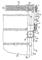
- Fig. 4 is a sectional door 30 with a door leaf 31, a frame 32, a torsion spring shaft 33 and a door drive device 34 are shown.
- the torsion spring shaft 33 is with the door leaf 31 is connected in a known manner via a cable with a cable drum 35.
- the door drive device 34 has a door drive motor unit in the form of a self-locking worm gear, which can be decoupled for emergencies 36 and the gate drive torque transmission device 20 or as shown a second embodiment 40 of a gate drive torque transmission device for the transmission of torques between the geared motor 36 and the Torsion spring shaft 33. Via the door drive torque transmission device 40, the torsion spring shaft 33 and the cable 35 drives the door drive device 34 the opening and closing movement of the door leaf 31.
- the geared motor 36 has one with the Frame 32 stationary drive housing 37, the connection between the frame 32 and drive housing 37 is shown at 38.
- the second embodiment of the door drive torque transmission device 40 is different from the first embodiment 20 only by the type of connection between the bearing parts 5 and 6.
- the two profiles 5 and 6 are in the second embodiment of the door drive torque transmission device 40 connected only by a single elastic junction 41, the same is constructed as the junctions 7 and 8 of the first embodiment.
- the connection point 41 42 In the circumferential direction to a pivot axis thus created by the connection point 41 42 are the two profiles 5 and 6 against an elastic element, not shown in FIG Form of a compression spring between the profiles 5 and 6 or the like relative to each other pivotable.
- At 43 there is another hole for a further selectable arrangement of the bolt 10 of the connection point 41 indicated in the outer profile 5.
- the Outer profile 5 is with a screw connection 44 in a suitable selectable orientation the drive housing 37 firmly connected.
- Embodiment 50 for the gate drive torque transmission device of the gate drive device 34 for the transmission of torques between the door drive motor unit, such as the gear motor 36 of a shaft gate drive, and a gate shaft, such as the torsion spring shaft 33, using the same reference numerals for corresponding Parts as explained in the previously described embodiments 20 and 40 in more detail.
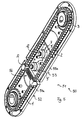
- the third embodiment of the door drive torque transmission device 50 is comparable in function and essential structure to first embodiment 20, wherein the two bearing parts for storing the drive member and the driven member however not by individual parts 5 and 6 of a chain bone 4, but as individual parts one acting as a storage device and at the same time protecting the chain transmission Transmission housing 51 are formed. Accordingly, the transmission case 51 by two separately executed, decoupled and only elastic to each other connected bearing parts, a drive link bearing part 52 and an output link bearing part 53 formed. Both bearing parts 52, 53 are essentially identical by two constructed, mirror-image interconnected housing shells 54a and 54b or 55a and 55b, each of which holds one of the sprockets 1 and 3 between them educated.
- the bearing parts 52 and 53 engage with a few millimeters of play between them telescopically.
- the drive link bearing part 52 is provided with bores 12a, 12b, 12c for connection to the drive housing 37 of the 3 shown in Fig. Geared motor.
- the two bearing parts 52, 53 are over the two elastic connection points 7 and 8 an elastic pivoting movement and translatory sliding movement in particular parallel to the chain plane or connected perpendicular to the axes of rotation of the sprockets 1 and 3.
- the door drive torque transmission device 50 is removed halved housing shells 54b and 55b shown.
- the chain 2 is within the bearing parts 52, 53 and outside the connection points 7 and 8.
- a tensioning device 56 tensions the two strands of chain 2 by elastic contraction.
- the two Junctions 7 and 8 are integral with the housing shells 55a and 55b of the output member bearing part 53 executed tubes 9 'with the housing shells 54a and 54b of the drive member bearing part 52 connectable bolts 10 and between the tubes 9 'and the bolts 10 arranged rubber bushings 11 are formed.
- the output shaft of the geared motor 36 and the torsion spring shaft for detection of the respective sprocket 1 or 3 is adapted in this form.
- Gate drive torque transmission device 50 become torsional vibrations and Impacts as well as a non-circular running of the door shaft due to the elastic connection points 7 and 8 damped relative movement and in particular relative pivoting between cushioned the individual parts 52, 53 of the transmission housing. This protects it Gate and gate drive motor assembly 36 and also the gate drive torque transmission device 50 themselves.
- Exemplary Shore hardnesses for the rubber bushings 11 are between approx. 50 and 100, Shore hardness 90 is currently preferred.
Landscapes
- Engineering & Computer Science (AREA)
- Structural Engineering (AREA)
- Architecture (AREA)
- Civil Engineering (AREA)
- Power-Operated Mechanisms For Wings (AREA)
- Elevator Door Apparatuses (AREA)
- Portable Nailing Machines And Staplers (AREA)
- Devices For Conveying Motion By Means Of Endless Flexible Members (AREA)
Description
- Fig. 1
- eine Torantriebsdrehmomentübertragungsvorrichtung zum Übertragen eines Drehmoments von einer Abtriebswelle eines Getriebemotors auf eine mit einem zu öffnenden und zu schließenden Tor verbundenen Torwelle;
- Fig. 2
- einen Schnitt entlang der Linie A - A von Fig. 1.
- Fig. 3
- eine Teilrückansicht auf ein mit einer Torantriebsvorrichtung mit einer Torantriebsdrehmomentübertragungsvorrichtung in einer weiteren Ausführungsform versehenes Tor;
- Fig. 4
- eine perspektivische Ansicht einer Torantriebsdrehmomentübertragungsvorrichtung für eine Torantriebsvorrichtung in noch einer weiteren Ausführungsform; und
- Fig. 5
- eine perspektivische Ansicht der Torantriebsdrehmomentübertragungsvorrichtung nach Fig. 4 mit geöffnetem Gehäuse.
Claims (12)
- Torantriebsdrehmomentübertragungsvorrichtung (20, 40, 50) zur Übertragung von Drehmomenten zwischen einem Torantriebsmotoraggregat, insbesondere einem Getriebemotor (36), und einer mit einem Torblatt (31) verbundenen Torwelle (33) mit einem mit dem Torantriebsmotoraggregat (36) in Eingriff bringbaren, um eine erste Drehachse drehbaren Antriebsglied (1) und einem mit der Torwelle (33) in Eingriff bringbaren, um eine zweite Drehachse drehbaren Abtriebsglied (3), einer Lagereinrichtung (4, 51), in der die beiden Glieder (1, 3) mit voneinander beabstandeten Drehachsen gelagert sind, und einer getrieblichen Verbindung (2) zwischen diesen Gliedern (1, 3),
dadurch gekennzeichnet, dass die Lagereinrichtung (4, 51) mit einem Antriebsgliedlagerteil (5, 52) zum Lagern des Antriebsglieds (1) und einem davon getrennt ausgeführten Abtriebsgliedlagerteil (6, 53) zum Lagern des Abtriebsgliedes (3) versehen ist und dass die Lagerteile (5, 6; 52, 53) zur Dämpfung von Torsionsschwingungen oder Torsionsstößen miteinander elastisch verbunden sind. - Torantriebsdrehmomentübertragungsvorrichtung nach Anspruch 1,
dass die beiden Lagerteile (5, 6) in wählbarem Abstand zueinander elastisch miteinander verbindbar sind. - Torantriebsdrehmomentübertragungsvorrichtung nach einem der voranstehenden Ansprüche,
dadurch gekennzeichnet, dass die beiden Lagerteile (5, 6; 52, 53) wenigstens in einer senkrecht zu wenigstens einer der beiden Drehachsen verlaufenden Ebene (Ke) zueinander abwinkelbar oder verschwenkbar elastisch miteinander verbunden sind. - Torantriebsdrehmomentübertragungsvorrichtung nach einem der voranstehenden Ansprüche,
dadurch gekennzeichnet, dass die beiden Lagerteile (5, 6; 52, 53) über wenigstens zwei voneinander beabstandete Verbindungspunkte (7, 8) elastisch miteinander verbunden sind. - Torantriebsdrehmomentübertragungsvorrichtung nach Anspruch 4,
dadurch gekennzeichnet, dass die beiden Verbindungspunkte (7, 8) durch zwei voneinander beabstandet angeordnete Verbindungsblöcke oder -buchsen (11) aus elastischem Material gebildet werden, über die die beiden Lagerteile (5, 6; 52, 53) miteinander verbunden sind. - Torantriebsdrehmomentübertragungsvorrichtung nach einem der voranstehenden Ansprüche,
gekennzeichnet durch ein Sortiment von elastischen Verbindungselementen (11) zum Verbinden der beiden Lagerteile (5, 6; 52, 53) mit verschiedenen, insbesondere durch verschiedene Härten und/oder Abmessungen wie Außendurchmessern erzielten, elastischen Eigenschaften zur gezielten Einstellung der Steifigkeit und/oder der Torsionsschwingungsdämpfungscharakteristik durch Verwendung aus dem Sortiment ausgewählter Verbindungselemente (11) in der Lagereinrichtung (4, 51). - Torantriebsdrehmomentübertragungsvorrichtung nach einem der voranstehenden Ansprüche,
dadurch gekennzeichnet, dass die beiden Lagerteile (52, 53) miteinander elastisch gekoppelte, insbesondere teleskopartig eine relative Verschwenkung zulassend mit Spiel ineinandergreifende, Einzelteile eines als Lagereinrichtung wirkenden Drehmomentübertragungsgehäuses (51) sind; vorzugsweise dergestalt, dass die Einzelteile (52, 53) jeweils im wesentlichen aus zwei, insbesondere identischen, miteinander verbundenen Gehäuseschalen (54a, 54b; 55a, 55b) gebildet sind. - Torantriebsdrehmomentübertragungsvorrichtung nach einem der voranstehenden Ansprüche,
dadurch gekennzeichnet, dass die getriebliche Verbindung durch wenigstens ein Endlos-Zugmittel wie Kette (2), Zahngurt oder Riemen gebildet ist und jedes der beiden Glieder ein Zugmittelrad (1, 3) aufweist, das mit dem wenigstens einen Zugmittel in form- oder reibschlüssigen Eingriff ist. - Torantriebsdrehmomentübertragungsvorrichtung nach Anspruch 7 und 8,
dadurch gekennzeichnet, dass ein durch das wenigstens eine Zugmittel (2) und die Zugmittelräder (1, 3) gebildete Zugmittelgetriebe von den Gehäuseschalen (54a, 54b; 55a, 55b) des Drehmomentübertragungsgehäuses (51) umgeben ist, wobei insbesondere eine die beiden Trume des Zugmittels (2) elastisch zueinander ziehende Zugmittelspannvorrichtung (56) innerhalb des Drehmomentübertragungsgehäuses (51) vorgesehen ist. - Motorische Torantriebsvorrichtung (34) zum Antreiben eines Torblatts (31) über eine mit dem Torblatt (31) verbundene Torwelle, wie Torsionsfederwelle (33) eines Überkopftores (30) oder Wickelwelle eines Rolltores, mit einem Torantriebsmotoraggregat, insbesondere einem Getriebemotor (36),
gekennzeichnet durch eine Torantriebsdrehmomentübertragungsvorrichtung (20, 40, 50) nach einem der voranstehenden Ansprüche zur Übertragung von Drehmomenten zwischen dem Torantriebsmotoraggregat (36) und der Torwelle (33). - Torantriebsvorrichtung nach Anspruch 10,
dadurch gekennzeichnet, dass das Antriebsgliedlagerteil (5, 52) mit einem ortsfest angeordneten Antriebsgehäuse (37) des Torantriebsmotoraggregats (36), insbesondere in wählbarer Ausrichtung, fest verbindbar ist, das Abtriebsgliedlagerteil (6, 53) aufgrund der elastischen Verbindung der beiden Lagerteile (5, 6; 52, 53) aber von dem Antriebsgehäuse (37) zur Dämpfung von Torsionsschwingungen und -stößen elastisch entkoppelt ist. - Tor, insbesondere Überkopftor - wie Sektionaltor (30) - oder Rolltor, mit einem zwischen seiner Offen- und Schließstellung hin und her beweglichen Torblatt (31) und einer zum Antreiben oder Unterstützung der Torblattbewegung mit dem Torblatt (31) verbunden Torwelle, wie insbesondere Torsionsfederwelle (33) des Überkopftores (30) oder Wickelwelle des Rolltores,
gekennzeichnet durch eine Torantriebsdrehmomentübertragungsvorrichtung (20, 40, 50) nach einem der Ansprüche 1 bis 9 und/oder eine Torantriebsvorrichtung (34) nach einem der Ansprüche 10 oder 11.
Priority Applications (2)
| Application Number | Priority Date | Filing Date | Title |
|---|---|---|---|
| PL352627A PL200369B1 (pl) | 2001-03-19 | 2002-03-05 | Urządzenie do podnoszenia bramy |
| US10/105,127 US6789599B2 (en) | 2001-03-19 | 2002-03-15 | Door driving-mechanism torque transmission, motorized door driving mechanism provided therewith, and door provided therewith |
Applications Claiming Priority (4)
| Application Number | Priority Date | Filing Date | Title |
|---|---|---|---|
| DE10113229 | 2001-03-19 | ||
| DE10113229 | 2001-03-19 | ||
| DE10114288 | 2001-03-23 | ||
| DE10114288 | 2001-03-23 |
Publications (2)
| Publication Number | Publication Date |
|---|---|
| EP1225296A1 EP1225296A1 (de) | 2002-07-24 |
| EP1225296B1 true EP1225296B1 (de) | 2002-07-31 |
Family
ID=26008824
Family Applications (1)
| Application Number | Title | Priority Date | Filing Date |
|---|---|---|---|
| EP01111691A Expired - Lifetime EP1225296B1 (de) | 2001-03-19 | 2001-05-14 | Torantriebsdrehmomentübertragungsvorrichtung, damit versehene motorische Torantriebsvorrichtung sowie damit versehenes Tor |
Country Status (4)
| Country | Link |
|---|---|
| EP (1) | EP1225296B1 (de) |
| AT (1) | ATE221611T1 (de) |
| DE (1) | DE50100013D1 (de) |
| DK (1) | DK1225296T3 (de) |
Cited By (1)
| Publication number | Priority date | Publication date | Assignee | Title |
|---|---|---|---|---|
| WO2026032650A1 (en) * | 2024-08-05 | 2026-02-12 | Assa Abloy Entrance Systems Ab | Transmission assembly for jackshaft conversion from a ceiling garage door opener |
Families Citing this family (3)
| Publication number | Priority date | Publication date | Assignee | Title |
|---|---|---|---|---|
| DE102008034359B4 (de) * | 2008-07-23 | 2014-07-31 | Hörmann KG Antriebstechnik | Verfahren zur Herstellung eines Wellentorantriebs sowie eines damit versehenen Tores und Wellentorantriebssystem zum Durchführen dieses Verfahrens |
| DE102017106444A1 (de) * | 2017-03-24 | 2018-09-27 | Hörmann KG Antriebstechnik | Drehmomentübertragungsvorrichtung, Torantriebsvorrichtung und damit versehenes Tor |
| CN116537689B (zh) * | 2023-06-13 | 2025-10-17 | 广州市煦雅家居用品有限公司 | 一种伸缩防护门栏 |
Family Cites Families (3)
| Publication number | Priority date | Publication date | Assignee | Title |
|---|---|---|---|---|
| GB2005761B (en) * | 1977-10-12 | 1982-02-17 | Marshall P B | Door operating appliance |
| DE3943758C2 (de) | 1989-05-12 | 1996-01-04 | Hoermann Kg Antrieb Steuertec | Getriebe |
| DE4221000C2 (de) | 1992-06-26 | 1995-09-21 | Marantec Antrieb Steuerung | Motorische Antriebseinrichtung für ein Torblatt |
-
2001
- 2001-05-14 DE DE50100013T patent/DE50100013D1/de not_active Expired - Lifetime
- 2001-05-14 DK DK01111691T patent/DK1225296T3/da active
- 2001-05-14 AT AT01111691T patent/ATE221611T1/de not_active IP Right Cessation
- 2001-05-14 EP EP01111691A patent/EP1225296B1/de not_active Expired - Lifetime
Cited By (1)
| Publication number | Priority date | Publication date | Assignee | Title |
|---|---|---|---|---|
| WO2026032650A1 (en) * | 2024-08-05 | 2026-02-12 | Assa Abloy Entrance Systems Ab | Transmission assembly for jackshaft conversion from a ceiling garage door opener |
Also Published As
| Publication number | Publication date |
|---|---|
| DE50100013D1 (de) | 2002-09-05 |
| ATE221611T1 (de) | 2002-08-15 |
| DK1225296T3 (da) | 2002-11-11 |
| EP1225296A1 (de) | 2002-07-24 |
Similar Documents
| Publication | Publication Date | Title |
|---|---|---|
| DE19934935B4 (de) | Umschlingungsmittel | |
| EP1437528A2 (de) | Riemenspannvorrichtung | |
| DE102014003222B4 (de) | Koaxiale Federanordnung | |
| EP2029843A1 (de) | Vorrichtung zur übertragung eines drehmomentes | |
| DE10325232B4 (de) | Scharniervorrichtung | |
| EP2064465B1 (de) | Getriebevorrichtung | |
| DE102018215451A1 (de) | Kraftrad mit einer Spannvorrichtung zum Spannen eines Zugorgans und Spannvorrichtung für ein Kraftrad | |
| EP1475503A2 (de) | Klappenantrieb für eine Klappe | |
| EP2212499B1 (de) | Verfahren zur herstellung eines torantriebs; torantriebssystem zum durchführen dieses verfahrens sowie verwendung eines damit hergestellten torantriebs | |
| DE102008026707A1 (de) | Drehwellenanordnung für ein Tor, insbesondere für ein Rolltor, und ein solches Tor | |
| EP1558859B1 (de) | Feder- und dämpfungsvorrichtung | |
| EP1225296A1 (de) | Torantriebsdrehmomentübertragungsvorrichtung, damit versehene motorische Torantriebsvorrichtung sowie damit versehenes Tor | |
| DE4036900A1 (de) | Antreibbares schwenkgelenk fuer klappen o. dgl. an kraftfahrzeugen | |
| DE4210523A1 (de) | Kombinierter Schub- und Zugantrieb | |
| EP0766794B1 (de) | Kupplung | |
| DE102017216220B4 (de) | Verstellbarer Stabilisator | |
| DE202005007605U1 (de) | Tor mit Wellentorantrieb | |
| EP4136366B1 (de) | Getriebe, antriebsanordnung und spinnereimaschine | |
| DE3614096C2 (de) | ||
| DE3804861A1 (de) | Einrichtung zum antrieb eines gelenkelementes eines roboters | |
| DE102017103796B4 (de) | Öffnungsmechanismus für einen schmetterlingsdeckel | |
| EP2905409A1 (de) | Stellvorrichtung für einen Flügel sowie Vorrichtung zur Einstellung von mehreren Flügeln | |
| DE19524308A1 (de) | Rollenbahn | |
| DE19505688C2 (de) | Antriebssystem mit zwei Endlos-Kraftübertragungsmittel | |
| DE10209723B4 (de) | Einrichtung zur Dämpfung von Schwingungen in Zugmittelantrieben |
Legal Events
| Date | Code | Title | Description |
|---|---|---|---|
| GRAG | Despatch of communication of intention to grant |
Free format text: ORIGINAL CODE: EPIDOS AGRA |
|
| GRAG | Despatch of communication of intention to grant |
Free format text: ORIGINAL CODE: EPIDOS AGRA |
|
| GRAG | Despatch of communication of intention to grant |
Free format text: ORIGINAL CODE: EPIDOS AGRA |
|
| GRAH | Despatch of communication of intention to grant a patent |
Free format text: ORIGINAL CODE: EPIDOS IGRA |
|
| GRAH | Despatch of communication of intention to grant a patent |
Free format text: ORIGINAL CODE: EPIDOS IGRA |
|
| PUAI | Public reference made under article 153(3) epc to a published international application that has entered the european phase |
Free format text: ORIGINAL CODE: 0009012 |
|
| GRAA | (expected) grant |
Free format text: ORIGINAL CODE: 0009210 |
|
| 17P | Request for examination filed |
Effective date: 20010606 |
|
| AK | Designated contracting states |
Kind code of ref document: A1 Designated state(s): AT BE CH CY DE DK ES FI FR GB GR IE IT LI LU MC NL PT SE TR |
|
| AX | Request for extension of the european patent |
Free format text: AL;LT;LV;MK;RO;SI |
|
| AK | Designated contracting states |
Kind code of ref document: B1 Designated state(s): AT BE CH CY DE DK ES FI FR GB GR IE IT LI LU MC NL PT SE TR |
|
| AX | Request for extension of the european patent |
Free format text: AL;LT;LV;MK;RO;SI |
|
| PG25 | Lapsed in a contracting state [announced via postgrant information from national office to epo] |
Ref country code: FI Free format text: LAPSE BECAUSE OF FAILURE TO SUBMIT A TRANSLATION OF THE DESCRIPTION OR TO PAY THE FEE WITHIN THE PRESCRIBED TIME-LIMIT Effective date: 20020731 Ref country code: GB Free format text: LAPSE BECAUSE OF FAILURE TO SUBMIT A TRANSLATION OF THE DESCRIPTION OR TO PAY THE FEE WITHIN THE PRESCRIBED TIME-LIMIT Effective date: 20020731 Ref country code: IE Free format text: LAPSE BECAUSE OF FAILURE TO SUBMIT A TRANSLATION OF THE DESCRIPTION OR TO PAY THE FEE WITHIN THE PRESCRIBED TIME-LIMIT Effective date: 20020731 Ref country code: TR Free format text: LAPSE BECAUSE OF FAILURE TO SUBMIT A TRANSLATION OF THE DESCRIPTION OR TO PAY THE FEE WITHIN THE PRESCRIBED TIME-LIMIT Effective date: 20020731 Ref country code: GR Free format text: LAPSE BECAUSE OF FAILURE TO SUBMIT A TRANSLATION OF THE DESCRIPTION OR TO PAY THE FEE WITHIN THE PRESCRIBED TIME-LIMIT Effective date: 20020731 |
|
| REF | Corresponds to: |
Ref document number: 221611 Country of ref document: AT Date of ref document: 20020815 Kind code of ref document: T |
|
| REG | Reference to a national code |
Ref country code: CH Ref legal event code: EP Ref country code: GB Ref legal event code: FG4D Free format text: NOT ENGLISH |
|
| REG | Reference to a national code |
Ref country code: IE Ref legal event code: FG4D Free format text: GERMAN |
|
| REF | Corresponds to: |
Ref document number: 50100013 Country of ref document: DE Date of ref document: 20020905 |
|
| REG | Reference to a national code |
Ref country code: DK Ref legal event code: T3 |
|
| PG25 | Lapsed in a contracting state [announced via postgrant information from national office to epo] |
Ref country code: PT Free format text: LAPSE BECAUSE OF FAILURE TO SUBMIT A TRANSLATION OF THE DESCRIPTION OR TO PAY THE FEE WITHIN THE PRESCRIBED TIME-LIMIT Effective date: 20021118 |
|
| ET | Fr: translation filed | ||
| GBV | Gb: ep patent (uk) treated as always having been void in accordance with gb section 77(7)/1977 [no translation filed] |
Effective date: 20020731 |
|
| PG25 | Lapsed in a contracting state [announced via postgrant information from national office to epo] |
Ref country code: ES Free format text: LAPSE BECAUSE OF FAILURE TO SUBMIT A TRANSLATION OF THE DESCRIPTION OR TO PAY THE FEE WITHIN THE PRESCRIBED TIME-LIMIT Effective date: 20030130 |
|
| REG | Reference to a national code |
Ref country code: IE Ref legal event code: FD4D Ref document number: 1225296E Country of ref document: IE |
|
| AKX | Designation fees paid |
Designated state(s): AT BE CH CY DE DK ES FI FR GB GR IE IT LI LU MC NL PT SE TR |
|
| PLBI | Opposition filed |
Free format text: ORIGINAL CODE: 0009260 |
|
| PLBQ | Unpublished change to opponent data |
Free format text: ORIGINAL CODE: EPIDOS OPPO |
|
| PG25 | Lapsed in a contracting state [announced via postgrant information from national office to epo] |
Ref country code: LU Free format text: LAPSE BECAUSE OF NON-PAYMENT OF DUE FEES Effective date: 20030514 Ref country code: CY Free format text: LAPSE BECAUSE OF FAILURE TO SUBMIT A TRANSLATION OF THE DESCRIPTION OR TO PAY THE FEE WITHIN THE PRESCRIBED TIME-LIMIT Effective date: 20030514 |
|
| PG25 | Lapsed in a contracting state [announced via postgrant information from national office to epo] |
Ref country code: MC Free format text: LAPSE BECAUSE OF NON-PAYMENT OF DUE FEES Effective date: 20030531 Ref country code: BE Free format text: LAPSE BECAUSE OF NON-PAYMENT OF DUE FEES Effective date: 20030531 |
|
| PLBF | Reply of patent proprietor to notice(s) of opposition |
Free format text: ORIGINAL CODE: EPIDOS OBSO |
|
| 26 | Opposition filed |
Opponent name: MARANTEC ANTRIEBS- UND STEUERUNGSTECHNIK GMBH & Effective date: 20030415 |
|
| NLR1 | Nl: opposition has been filed with the epo |
Opponent name: MARANTEC ANTRIEBS- UND STEUERUNGSTECHNIK GMBH & CO |
|
| PLBB | Reply of patent proprietor to notice(s) of opposition received |
Free format text: ORIGINAL CODE: EPIDOSNOBS3 |
|
| BERE | Be: lapsed |
Owner name: *HORMANN K.G. ANTRIEBSTECHNIK Effective date: 20030531 |
|
| PLCK | Communication despatched that opposition was rejected |
Free format text: ORIGINAL CODE: EPIDOSNREJ1 |
|
| PG25 | Lapsed in a contracting state [announced via postgrant information from national office to epo] |
Ref country code: LI Free format text: LAPSE BECAUSE OF NON-PAYMENT OF DUE FEES Effective date: 20050531 Ref country code: CH Free format text: LAPSE BECAUSE OF NON-PAYMENT OF DUE FEES Effective date: 20050531 |
|
| PLBN | Opposition rejected |
Free format text: ORIGINAL CODE: 0009273 |
|
| STAA | Information on the status of an ep patent application or granted ep patent |
Free format text: STATUS: OPPOSITION REJECTED |
|
| 27O | Opposition rejected |
Effective date: 20050316 |
|
| NLR2 | Nl: decision of opposition |
Effective date: 20050316 |
|
| REG | Reference to a national code |
Ref country code: CH Ref legal event code: PL |
|
| PGFP | Annual fee paid to national office [announced via postgrant information from national office to epo] |
Ref country code: DK Payment date: 20100525 Year of fee payment: 10 |
|
| PGFP | Annual fee paid to national office [announced via postgrant information from national office to epo] |
Ref country code: NL Payment date: 20100527 Year of fee payment: 10 Ref country code: AT Payment date: 20100512 Year of fee payment: 10 |
|
| PGFP | Annual fee paid to national office [announced via postgrant information from national office to epo] |
Ref country code: SE Payment date: 20100520 Year of fee payment: 10 |
|
| REG | Reference to a national code |
Ref country code: NL Ref legal event code: V1 Effective date: 20111201 |
|
| REG | Reference to a national code |
Ref country code: DK Ref legal event code: EBP |
|
| REG | Reference to a national code |
Ref country code: SE Ref legal event code: EUG |
|
| PG25 | Lapsed in a contracting state [announced via postgrant information from national office to epo] |
Ref country code: NL Free format text: LAPSE BECAUSE OF NON-PAYMENT OF DUE FEES Effective date: 20111201 |
|
| REG | Reference to a national code |
Ref country code: AT Ref legal event code: MM01 Ref document number: 221611 Country of ref document: AT Kind code of ref document: T Effective date: 20110514 |
|
| PG25 | Lapsed in a contracting state [announced via postgrant information from national office to epo] |
Ref country code: AT Free format text: LAPSE BECAUSE OF NON-PAYMENT OF DUE FEES Effective date: 20110514 |
|
| PG25 | Lapsed in a contracting state [announced via postgrant information from national office to epo] |
Ref country code: DK Free format text: LAPSE BECAUSE OF NON-PAYMENT OF DUE FEES Effective date: 20110531 |
|
| PG25 | Lapsed in a contracting state [announced via postgrant information from national office to epo] |
Ref country code: SE Free format text: LAPSE BECAUSE OF NON-PAYMENT OF DUE FEES Effective date: 20110515 |
|
| REG | Reference to a national code |
Ref country code: DE Ref legal event code: R082 Ref document number: 50100013 Country of ref document: DE Representative=s name: KASTEL PATENTANWAELTE PARTG MBB, DE Ref country code: DE Ref legal event code: R082 Ref document number: 50100013 Country of ref document: DE Representative=s name: KASTEL PATENTANWAELTE, DE |
|
| REG | Reference to a national code |
Ref country code: FR Ref legal event code: PLFP Year of fee payment: 16 |
|
| PGFP | Annual fee paid to national office [announced via postgrant information from national office to epo] |
Ref country code: IT Payment date: 20160524 Year of fee payment: 16 Ref country code: FR Payment date: 20160523 Year of fee payment: 16 |
|
| REG | Reference to a national code |
Ref country code: FR Ref legal event code: ST Effective date: 20180131 |
|
| PG25 | Lapsed in a contracting state [announced via postgrant information from national office to epo] |
Ref country code: FR Free format text: LAPSE BECAUSE OF NON-PAYMENT OF DUE FEES Effective date: 20170531 Ref country code: IT Free format text: LAPSE BECAUSE OF NON-PAYMENT OF DUE FEES Effective date: 20170514 |
|
| PGFP | Annual fee paid to national office [announced via postgrant information from national office to epo] |
Ref country code: DE Payment date: 20190729 Year of fee payment: 19 |
|
| REG | Reference to a national code |
Ref country code: DE Ref legal event code: R119 Ref document number: 50100013 Country of ref document: DE |
|
| PG25 | Lapsed in a contracting state [announced via postgrant information from national office to epo] |
Ref country code: DE Free format text: LAPSE BECAUSE OF NON-PAYMENT OF DUE FEES Effective date: 20201201 |