EP1225071A1 - Einheit zur Klimatisierung und Verteilung von Luft in der Fahrgastzelle eines Kraftfahrzeuges - Google Patents
Einheit zur Klimatisierung und Verteilung von Luft in der Fahrgastzelle eines Kraftfahrzeuges Download PDFInfo
- Publication number
- EP1225071A1 EP1225071A1 EP01129081A EP01129081A EP1225071A1 EP 1225071 A1 EP1225071 A1 EP 1225071A1 EP 01129081 A EP01129081 A EP 01129081A EP 01129081 A EP01129081 A EP 01129081A EP 1225071 A1 EP1225071 A1 EP 1225071A1
- Authority
- EP
- European Patent Office
- Prior art keywords
- air flow
- air
- flow
- mixing
- unit
- Prior art date
- Legal status (The legal status is an assumption and is not a legal conclusion. Google has not performed a legal analysis and makes no representation as to the accuracy of the status listed.)
- Withdrawn
Links
Images
Classifications
-
- B—PERFORMING OPERATIONS; TRANSPORTING
- B60—VEHICLES IN GENERAL
- B60H—ARRANGEMENTS OF HEATING, COOLING, VENTILATING OR OTHER AIR-TREATING DEVICES SPECIALLY ADAPTED FOR PASSENGER OR GOODS SPACES OF VEHICLES
- B60H1/00—Heating, cooling or ventilating [HVAC] devices
- B60H1/00007—Combined heating, ventilating, or cooling devices
- B60H1/00021—Air flow details of HVAC devices
- B60H1/00064—Air flow details of HVAC devices for sending air streams of different temperatures into the passenger compartment
- B60H1/00071—Air flow details of HVAC devices for sending air streams of different temperatures into the passenger compartment the air passing only one heat exchanger
-
- B—PERFORMING OPERATIONS; TRANSPORTING
- B60—VEHICLES IN GENERAL
- B60H—ARRANGEMENTS OF HEATING, COOLING, VENTILATING OR OTHER AIR-TREATING DEVICES SPECIALLY ADAPTED FOR PASSENGER OR GOODS SPACES OF VEHICLES
- B60H1/00—Heating, cooling or ventilating [HVAC] devices
- B60H1/00007—Combined heating, ventilating, or cooling devices
- B60H1/00021—Air flow details of HVAC devices
- B60H2001/00114—Heating or cooling details
- B60H2001/00128—Electric heaters
-
- B—PERFORMING OPERATIONS; TRANSPORTING
- B60—VEHICLES IN GENERAL
- B60H—ARRANGEMENTS OF HEATING, COOLING, VENTILATING OR OTHER AIR-TREATING DEVICES SPECIALLY ADAPTED FOR PASSENGER OR GOODS SPACES OF VEHICLES
- B60H1/00—Heating, cooling or ventilating [HVAC] devices
- B60H1/00007—Combined heating, ventilating, or cooling devices
- B60H1/00021—Air flow details of HVAC devices
- B60H2001/0015—Temperature regulation
- B60H2001/00164—Temperature regulation with more than one by-pass
-
- B—PERFORMING OPERATIONS; TRANSPORTING
- B60—VEHICLES IN GENERAL
- B60H—ARRANGEMENTS OF HEATING, COOLING, VENTILATING OR OTHER AIR-TREATING DEVICES SPECIALLY ADAPTED FOR PASSENGER OR GOODS SPACES OF VEHICLES
- B60H1/00—Heating, cooling or ventilating [HVAC] devices
- B60H1/00007—Combined heating, ventilating, or cooling devices
- B60H1/00021—Air flow details of HVAC devices
- B60H2001/00185—Distribution of conditionned air
- B60H2001/002—Distribution of conditionned air to front and rear part of passenger compartment
Definitions
- This invention relates to a unit for conditioning and distributing air in the passenger compartment of a motor vehicle, with front and rear seats. More precisely, the invention relates to a unit which can be used to independently adjust the temperature and distribution of the conditioned air flow directed to the front seats and to the rear seats.
- the objective of this invention is to provide an air conditioning and distributing system with separate adjustment for the driver, the front passenger and the rear passengers, which is simpler and more compact than the known solutions.
- this objective is attained by means of a unit which characteristics are described in the main claim.
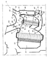
- numeral 10 generically indicates a unit for conditioning and distributing air in the passenger compartment of a motor vehicle.
- the unit 10 comprises a plastic material enclosure 12, containing air flow conditioning means, consisting of an evaporator 14 and a heating unit 16.
- the heating unit 16 comprises a radiator 18 and an electrical heater 20.
- a filter 22 is arranged upstream to the evaporator.
- the enclosure 12 creates an inlet chamber 24 for the air to be conditioned and, downstream to the evaporator 14, a cold air flow collection chamber 26.
- the enclosure 12 also creates a hot air collection chamber 28, downstream to the heater unit 18, 20, and a front seat air flow mixing chamber 30.
- the mixing chamber 30 is arranged over the heater 18, 20 and communicates with the cold air collection chamber 26 and with the cold air flow collection chamber 28 via apertures 32, 34 equipped with adjustable mixing flaps 36, 38.
- the front seat air flow mixing chamber 30 also communicates with a distribution channel 40, which sends the air flow to the base of the windscreen and with a channel 42 for distributing the air flow to the front seats.
- the channel 42 is split into a channel 44, which sends the air flow to the front vents (not shown), and into a channel 46, which sends the air flow to the feet of the passengers occupying the front seats.
- the distribution channels 40, 44 and 46 are equipped with respective distribution flaps 48, 50, 52.
- the part of the air flow conditioning and distributing unit described to this point can be used to adjust the temperature and the distribution of the air flow directed towards the front seats.
- this part of the conditioning and distributing unit presents a longitudinal separation wall (not shown), splitting the unit 10 in the transversal direction in two areas which can be adjusted in a reciprocally separate way for mixing and distributing the air flows destined to the driver and to the front seat passenger in the motor vehicle.
- the conditioning and distributing unit 10 also comprises a chamber 54 for mixing the flow of air destined to be sent to the rear seat passengers in the vehicle.
- the mixing chamber 54 is arranged under the channel 46 for distributing the air flow towards the feet of the passengers in the front seats.
- the mixing chamber 54 communicates with the hot air flow collection chamber 28 via an aperture 56, which is equipped with a flap 58 which can assume an open position (shown with the dotted line) and a closed position (shown with the solid line). As shown below, the flap 58 is closed when the user wants to exploit the maximum power of the heater unit 18, 20, for fast windscreen defrosting.
- the conditioning and distributing unit 10 comprises a channel 60 for collecting the cold air flow for the rear seats.
- the collection channel is extended under the heater unit 18, 20.
- One end communicates with the cold air flow collection chamber 26 and a second end 64 communicates with the rear seat air flow mixing chamber 54.
- An adjustable mixing flap 66 is arranged on the first end of the collection chamber 60.
- the rear seat air flow mixing chamber 54 communicates with two outlet conduits 68, 70, which convey the air flow towards the upper part and towards the feet of the rear seat passengers, respectively.
- An adjustable distribution flap 72 is used to adjust the air flows directed to the distribution conduits 68, 70.
- a fan (not shown) sends a flow of air to be conditioned into the inlet chamber 24. This flow of air is filtered by the filter 24 and cooled and dehumidified during the passage through the evaporator 14.
- the mixing flaps 36, 38 are used to adjust the air flow temperature, which is collected in the front seat air flow mixing chamber 30, considering that the cold air from collection chamber 26 is mixed with the hot air from chamber 28 (downstream to the heater unit 18, 20) in the mixing chamber 30.
- the opening or closing angle of the mixing flap 66 is used to adjust the temperature of the air flow, which is collected in the rear seat air flow mixing chamber 54. This is because, when the mixing flap 66 is in the position illustrated by the solid line, the collection channel 60 is not crossed by a flow of cold air, and when the flap 58 is in the position illustrated by the dotted line, a flow of hot air, which has crossed the lower part of the heater unit 18, 20, reaches the mixing chamber 54. By varying the position of the distribution flap 72, the flow of air can be directed towards the rear seats either to the upper part or to the feet of the rear seat passengers.
- the distribution flap 66 When the distribution flap 66 is in the position illustrated with a dotted line, only a flow of cold air reaches the mixing chamber 54 because the flap 66 entirely cuts off the flow of air which would cross the lower part of the heater unit 18, 20.
- the flap 66 can assume any intermediate position between the extreme positions shown in the figure to vary the temperature of the flow of air which is collected in the mixing chamber 54 between a minimum temperature and a maximum temperature.
- the fast windscreen defrosting function can be obtained very simply with the unit according to this invention.
- the flow of air which would normally be used for the rear seats, is directed towards the distribution conduit 40.
- the flaps 66 and 58 are arranged in the position shown with the solid line in which they close apertures 62 and 56 respectively. In this way, the entire flow of air is collected in the upper mixing chamber 30. This flow can consequently be directed towards the base of the window by closing the distribution flaps 50, 52.
Applications Claiming Priority (2)
| Application Number | Priority Date | Filing Date | Title |
|---|---|---|---|
| ITTO010036 | 2001-01-19 | ||
| IT2001TO000036A ITTO20010036A1 (it) | 2001-01-19 | 2001-01-19 | Gruppo per il trattamento e la distribuzione di aria nell'abitacolo di un veicolo. |
Publications (1)
| Publication Number | Publication Date |
|---|---|
| EP1225071A1 true EP1225071A1 (de) | 2002-07-24 |
Family
ID=11458400
Family Applications (1)
| Application Number | Title | Priority Date | Filing Date |
|---|---|---|---|
| EP01129081A Withdrawn EP1225071A1 (de) | 2001-01-19 | 2001-12-07 | Einheit zur Klimatisierung und Verteilung von Luft in der Fahrgastzelle eines Kraftfahrzeuges |
Country Status (7)
| Country | Link |
|---|---|
| US (1) | US20020108385A1 (de) |
| EP (1) | EP1225071A1 (de) |
| JP (1) | JP2002248925A (de) |
| BR (1) | BR0200090A (de) |
| CZ (1) | CZ2002130A3 (de) |
| IT (1) | ITTO20010036A1 (de) |
| PL (1) | PL351721A1 (de) |
Cited By (8)
| Publication number | Priority date | Publication date | Assignee | Title |
|---|---|---|---|---|
| WO2004014677A1 (de) * | 2002-07-29 | 2004-02-19 | Behr Gmbh & Co. | Kilmagehäuse |
| FR2844483A1 (fr) * | 2002-09-17 | 2004-03-19 | Denso Corp | Systeme de changement de direction d'air destine a des conduites d'air de vehicule |
| EP1535770A1 (de) * | 2003-11-28 | 2005-06-01 | Valeo Climatisation | Vorrichtung zum Belüften, Beheizen und/oder Kühlen von Fahrzeugräumen mit Zonentemperaturregelung |
| EP2030816A2 (de) | 2007-09-03 | 2009-03-04 | Behr GmbH & Co. KG | Klimaanlage für ein Kraftfahrzeug mit einer Fondraumklappe zum Mischen und Verteilen der Luft |
| EP2108535A1 (de) * | 2008-04-11 | 2009-10-14 | Behr France Rouffach SAS | Klimaanlage für ein Kraftfahrzeug |
| DE102014208698A1 (de) * | 2014-05-09 | 2015-11-12 | Mahle International Gmbh | Klimatisierungsanlage |
| WO2016008684A1 (en) | 2014-07-15 | 2016-01-21 | Valeo Klimasysteme Gmbh | Multi-zone air-conditioning device |
| EP2815906B1 (de) | 2012-02-14 | 2017-03-29 | Japan Climate Systems Corporation | Klimaanlagevorrichtung für fahrzeug |
Families Citing this family (3)
| Publication number | Priority date | Publication date | Assignee | Title |
|---|---|---|---|---|
| DE102005009325B4 (de) * | 2005-02-22 | 2014-08-28 | Halla Visteon Climate Control Corporation 95 | Luftbehandlungsanlage |
| US9145041B2 (en) * | 2007-07-31 | 2015-09-29 | Mahle International Gmbh | Air mixing apparatus for HVAC system |
| KR101492154B1 (ko) | 2008-12-09 | 2015-02-10 | 한라비스테온공조 주식회사 | 차량용 공조장치 |
Citations (4)
| Publication number | Priority date | Publication date | Assignee | Title |
|---|---|---|---|---|
| US4390124A (en) * | 1980-02-27 | 1983-06-28 | Saab-Scania Aktiebolag | Heating and ventilation system for vehicles |
| FR2778152A1 (fr) * | 1998-04-30 | 1999-11-05 | Valeo Climatisation | Installation de chauffage, ventilation et/ou climatisation d'un habitacle, notamment de vehicule automobile, a reglage de temperature par zones |
| JP2000062441A (ja) * | 1998-08-25 | 2000-02-29 | Denso Corp | 車両用空調装置 |
| JP2000062442A (ja) * | 1998-08-25 | 2000-02-29 | Denso Corp | 車両用空調装置 |
-
2001
- 2001-01-19 IT IT2001TO000036A patent/ITTO20010036A1/it unknown
- 2001-12-07 EP EP01129081A patent/EP1225071A1/de not_active Withdrawn
-
2002
- 2002-01-08 JP JP2002001487A patent/JP2002248925A/ja active Pending
- 2002-01-11 CZ CZ2002130A patent/CZ2002130A3/cs unknown
- 2002-01-15 PL PL02351721A patent/PL351721A1/xx not_active Application Discontinuation
- 2002-01-17 BR BR0200090-3A patent/BR0200090A/pt not_active Application Discontinuation
- 2002-01-18 US US10/050,569 patent/US20020108385A1/en not_active Abandoned
Patent Citations (4)
| Publication number | Priority date | Publication date | Assignee | Title |
|---|---|---|---|---|
| US4390124A (en) * | 1980-02-27 | 1983-06-28 | Saab-Scania Aktiebolag | Heating and ventilation system for vehicles |
| FR2778152A1 (fr) * | 1998-04-30 | 1999-11-05 | Valeo Climatisation | Installation de chauffage, ventilation et/ou climatisation d'un habitacle, notamment de vehicule automobile, a reglage de temperature par zones |
| JP2000062441A (ja) * | 1998-08-25 | 2000-02-29 | Denso Corp | 車両用空調装置 |
| JP2000062442A (ja) * | 1998-08-25 | 2000-02-29 | Denso Corp | 車両用空調装置 |
Non-Patent Citations (1)
| Title |
|---|
| PATENT ABSTRACTS OF JAPAN vol. 2000, no. 05 14 September 2000 (2000-09-14) * |
Cited By (15)
| Publication number | Priority date | Publication date | Assignee | Title |
|---|---|---|---|---|
| US7708055B2 (en) | 2002-07-29 | 2010-05-04 | Behr Gmbh & Co. Kg | Air-conditioner housing |
| WO2004014677A1 (de) * | 2002-07-29 | 2004-02-19 | Behr Gmbh & Co. | Kilmagehäuse |
| JP2005534566A (ja) * | 2002-07-29 | 2005-11-17 | ベール ゲーエムベーハー ウント コー カーゲー | 空調ハウジング |
| CN100341718C (zh) * | 2002-07-29 | 2007-10-10 | 贝洱两合公司 | 空调壳体 |
| FR2844483A1 (fr) * | 2002-09-17 | 2004-03-19 | Denso Corp | Systeme de changement de direction d'air destine a des conduites d'air de vehicule |
| DE10342811B4 (de) | 2002-09-17 | 2019-09-12 | Denso Corporation | Fahrzeug-Klimasystem |
| FR2862911A1 (fr) * | 2003-11-28 | 2005-06-03 | Valeo Climatisation | Dispositif de chauffage-ventilation et/ou climatisation d'un habitacle de vehicule avec reglage de temperature par zones |
| EP1535770A1 (de) * | 2003-11-28 | 2005-06-01 | Valeo Climatisation | Vorrichtung zum Belüften, Beheizen und/oder Kühlen von Fahrzeugräumen mit Zonentemperaturregelung |
| DE102007041689A1 (de) | 2007-09-03 | 2009-03-05 | Behr Gmbh & Co. Kg | Klimaanlage für ein Kraftfahrzeug mit einer Fondraumklappe zum Mischen und Verteilen der Luft |
| EP2030816A2 (de) | 2007-09-03 | 2009-03-04 | Behr GmbH & Co. KG | Klimaanlage für ein Kraftfahrzeug mit einer Fondraumklappe zum Mischen und Verteilen der Luft |
| EP2108535A1 (de) * | 2008-04-11 | 2009-10-14 | Behr France Rouffach SAS | Klimaanlage für ein Kraftfahrzeug |
| EP2815906B1 (de) | 2012-02-14 | 2017-03-29 | Japan Climate Systems Corporation | Klimaanlagevorrichtung für fahrzeug |
| DE102014208698A1 (de) * | 2014-05-09 | 2015-11-12 | Mahle International Gmbh | Klimatisierungsanlage |
| WO2016008684A1 (en) | 2014-07-15 | 2016-01-21 | Valeo Klimasysteme Gmbh | Multi-zone air-conditioning device |
| DE102014109925A1 (de) | 2014-07-15 | 2016-01-21 | Valeo Klimasysteme Gmbh | Mehrzonen-Klimatisierungseinrichtung |
Also Published As
| Publication number | Publication date |
|---|---|
| BR0200090A (pt) | 2002-10-22 |
| ITTO20010036A1 (it) | 2002-07-19 |
| ITTO20010036A0 (it) | 2001-01-19 |
| JP2002248925A (ja) | 2002-09-03 |
| CZ2002130A3 (cs) | 2002-09-11 |
| PL351721A1 (en) | 2002-07-29 |
| US20020108385A1 (en) | 2002-08-15 |
Similar Documents
| Publication | Publication Date | Title |
|---|---|---|
| JP3990556B2 (ja) | 2つの混合領域を有する自動車用空調装置 | |
| US7540321B2 (en) | Air conditioner for vehicle | |
| US5186237A (en) | Multi-zone HVAC system with an air bypass for individual flow control | |
| EP1564047B1 (de) | Fahrzeugklimaanlage | |
| US7819178B2 (en) | Vehicle air conditioner with flow diverting means | |
| EP1308326B1 (de) | Fahrzeugheizungs-, Lüftungs- und Klimaanlage mit verbesserter Heizungs- und Enteisungsleistung | |
| JPH1191336A (ja) | 自動車の暖房または空調装置 | |
| EP1225071A1 (de) | Einheit zur Klimatisierung und Verteilung von Luft in der Fahrgastzelle eines Kraftfahrzeuges | |
| US4898325A (en) | Automobile air conditioner with separate flow adjustment for central and side vents | |
| EP1361088A1 (de) | Luftverteilklappe mit Leitschaufeln für die Heiz- und Lüftungseinrichtung eines Kraftfahrzeugs | |
| US4343230A (en) | Auxiliary device for climate-control units in motor vehicles | |
| US6994157B1 (en) | Air conditioner | |
| US5050486A (en) | Air-conditioning system for vehicles | |
| JP3990276B2 (ja) | 空気ガイドボックス | |
| US20040014418A1 (en) | Air partitioning device for air conditioning system | |
| EP2036749B1 (de) | Klima- und Belüftungsanlage für ein Kraftfahrzeug | |
| US6634938B2 (en) | Air-conditioning installation with separate treatment for the rear of passenger compartment | |
| JP3857406B2 (ja) | 自動車用空気調和装置 | |
| JPS602965Y2 (ja) | 自動車用空調装置 | |
| JP2007526170A (ja) | 自動車用の空調装置 | |
| JP3972445B2 (ja) | 車両用空調装置 | |
| JP3972492B2 (ja) | 車両用空調装置 | |
| JPS6315043Y2 (de) | ||
| JPH062444B2 (ja) | 車両用空調装置 | |
| JP4551585B2 (ja) | 自動車用空気調和装置 |
Legal Events
| Date | Code | Title | Description |
|---|---|---|---|
| PUAI | Public reference made under article 153(3) epc to a published international application that has entered the european phase |
Free format text: ORIGINAL CODE: 0009012 |
|
| AK | Designated contracting states |
Kind code of ref document: A1 Designated state(s): AT BE CH CY DE DK ES FI FR GB GR IE IT LI LU MC NL PT SE TR |
|
| AX | Request for extension of the european patent |
Free format text: AL;LT;LV;MK;RO;SI |
|
| 17P | Request for examination filed |
Effective date: 20030107 |
|
| AKX | Designation fees paid |
Designated state(s): AT BE CH CY DE DK ES FI FR GB GR IE IT LI LU MC NL PT SE TR |
|
| 17Q | First examination report despatched |
Effective date: 20030505 |
|
| STAA | Information on the status of an ep patent application or granted ep patent |
Free format text: STATUS: THE APPLICATION IS DEEMED TO BE WITHDRAWN |
|
| 18D | Application deemed to be withdrawn |
Effective date: 20030916 |