EP1224458B1 - The meso sniffer: a device and method for active gas sampling using alternating flow - Google Patents
The meso sniffer: a device and method for active gas sampling using alternating flow Download PDFInfo
- Publication number
- EP1224458B1 EP1224458B1 EP00991851A EP00991851A EP1224458B1 EP 1224458 B1 EP1224458 B1 EP 1224458B1 EP 00991851 A EP00991851 A EP 00991851A EP 00991851 A EP00991851 A EP 00991851A EP 1224458 B1 EP1224458 B1 EP 1224458B1
- Authority
- EP
- European Patent Office
- Prior art keywords
- pump
- port
- chamber
- sensor head
- diaphragm pump
- Prior art date
- Legal status (The legal status is an assumption and is not a legal conclusion. Google has not performed a legal analysis and makes no representation as to the accuracy of the status listed.)
- Expired - Lifetime
Links
- 238000005070 sampling Methods 0.000 title claims abstract description 36
- 238000000034 method Methods 0.000 title claims description 15
- 239000012491 analyte Substances 0.000 claims abstract description 49
- 239000012530 fluid Substances 0.000 claims abstract description 29
- 238000010926 purge Methods 0.000 claims abstract description 23
- 230000004044 response Effects 0.000 claims abstract description 8
- 238000001914 filtration Methods 0.000 claims abstract 2
- 239000000126 substance Substances 0.000 claims description 35
- 238000005086 pumping Methods 0.000 abstract description 19
- 230000009471 action Effects 0.000 description 14
- 239000000463 material Substances 0.000 description 8
- 238000001514 detection method Methods 0.000 description 6
- 230000003993 interaction Effects 0.000 description 6
- 238000011896 sensitive detection Methods 0.000 description 6
- 230000008901 benefit Effects 0.000 description 4
- 230000002427 irreversible effect Effects 0.000 description 4
- 230000029058 respiratory gaseous exchange Effects 0.000 description 4
- 230000001360 synchronised effect Effects 0.000 description 4
- 230000000694 effects Effects 0.000 description 3
- 230000002441 reversible effect Effects 0.000 description 3
- 241001465754 Metazoa Species 0.000 description 2
- 230000008859 change Effects 0.000 description 2
- 238000006243 chemical reaction Methods 0.000 description 2
- 238000011109 contamination Methods 0.000 description 2
- 238000009792 diffusion process Methods 0.000 description 2
- 238000009825 accumulation Methods 0.000 description 1
- 230000002411 adverse Effects 0.000 description 1
- 230000009286 beneficial effect Effects 0.000 description 1
- 230000000903 blocking effect Effects 0.000 description 1
- 238000004140 cleaning Methods 0.000 description 1
- 238000003795 desorption Methods 0.000 description 1
- 230000008030 elimination Effects 0.000 description 1
- 238000003379 elimination reaction Methods 0.000 description 1
- 239000002360 explosive Substances 0.000 description 1
- 230000010354 integration Effects 0.000 description 1
- 230000007774 longterm Effects 0.000 description 1
- 238000004020 luminiscence type Methods 0.000 description 1
- 238000005259 measurement Methods 0.000 description 1
- 230000007935 neutral effect Effects 0.000 description 1
- 230000003287 optical effect Effects 0.000 description 1
- 239000002245 particle Substances 0.000 description 1
- 230000000704 physical effect Effects 0.000 description 1
- 238000000053 physical method Methods 0.000 description 1
- 229920000642 polymer Polymers 0.000 description 1
- 230000008569 process Effects 0.000 description 1
- 238000003672 processing method Methods 0.000 description 1
- 230000005855 radiation Effects 0.000 description 1
- 230000002829 reductive effect Effects 0.000 description 1
- 230000000717 retained effect Effects 0.000 description 1
- 230000035945 sensitivity Effects 0.000 description 1
- 238000000926 separation method Methods 0.000 description 1
- 238000001179 sorption measurement Methods 0.000 description 1
- 241000894007 species Species 0.000 description 1
Images

Classifications
-
- G—PHYSICS
- G01—MEASURING; TESTING
- G01N—INVESTIGATING OR ANALYSING MATERIALS BY DETERMINING THEIR CHEMICAL OR PHYSICAL PROPERTIES
- G01N33/00—Investigating or analysing materials by specific methods not covered by groups G01N1/00 - G01N31/00
- G01N33/0004—Gaseous mixtures, e.g. polluted air
- G01N33/0009—General constructional details of gas analysers, e.g. portable test equipment
- G01N33/0026—General constructional details of gas analysers, e.g. portable test equipment using an alternating circulation of another gas
-
- G—PHYSICS
- G01—MEASURING; TESTING
- G01N—INVESTIGATING OR ANALYSING MATERIALS BY DETERMINING THEIR CHEMICAL OR PHYSICAL PROPERTIES
- G01N1/00—Sampling; Preparing specimens for investigation
- G01N1/02—Devices for withdrawing samples
- G01N1/22—Devices for withdrawing samples in the gaseous state
- G01N1/24—Suction devices
-
- G—PHYSICS
- G01—MEASURING; TESTING
- G01N—INVESTIGATING OR ANALYSING MATERIALS BY DETERMINING THEIR CHEMICAL OR PHYSICAL PROPERTIES
- G01N33/00—Investigating or analysing materials by specific methods not covered by groups G01N1/00 - G01N31/00
- G01N33/0004—Gaseous mixtures, e.g. polluted air
- G01N33/0009—General constructional details of gas analysers, e.g. portable test equipment
- G01N33/0011—Sample conditioning
-
- Y—GENERAL TAGGING OF NEW TECHNOLOGICAL DEVELOPMENTS; GENERAL TAGGING OF CROSS-SECTIONAL TECHNOLOGIES SPANNING OVER SEVERAL SECTIONS OF THE IPC; TECHNICAL SUBJECTS COVERED BY FORMER USPC CROSS-REFERENCE ART COLLECTIONS [XRACs] AND DIGESTS
- Y10—TECHNICAL SUBJECTS COVERED BY FORMER USPC
- Y10T—TECHNICAL SUBJECTS COVERED BY FORMER US CLASSIFICATION
- Y10T436/00—Chemistry: analytical and immunological testing
- Y10T436/11—Automated chemical analysis
-
- Y—GENERAL TAGGING OF NEW TECHNOLOGICAL DEVELOPMENTS; GENERAL TAGGING OF CROSS-SECTIONAL TECHNOLOGIES SPANNING OVER SEVERAL SECTIONS OF THE IPC; TECHNICAL SUBJECTS COVERED BY FORMER USPC CROSS-REFERENCE ART COLLECTIONS [XRACs] AND DIGESTS
- Y10—TECHNICAL SUBJECTS COVERED BY FORMER USPC
- Y10T—TECHNICAL SUBJECTS COVERED BY FORMER US CLASSIFICATION
- Y10T436/00—Chemistry: analytical and immunological testing
- Y10T436/25—Chemistry: analytical and immunological testing including sample preparation
- Y10T436/25375—Liberation or purification of sample or separation of material from a sample [e.g., filtering, centrifuging, etc.]
-
- Y—GENERAL TAGGING OF NEW TECHNOLOGICAL DEVELOPMENTS; GENERAL TAGGING OF CROSS-SECTIONAL TECHNOLOGIES SPANNING OVER SEVERAL SECTIONS OF THE IPC; TECHNICAL SUBJECTS COVERED BY FORMER USPC CROSS-REFERENCE ART COLLECTIONS [XRACs] AND DIGESTS
- Y10—TECHNICAL SUBJECTS COVERED BY FORMER USPC
- Y10T—TECHNICAL SUBJECTS COVERED BY FORMER US CLASSIFICATION
- Y10T436/00—Chemistry: analytical and immunological testing
- Y10T436/25—Chemistry: analytical and immunological testing including sample preparation
- Y10T436/2575—Volumetric liquid transfer
-
- Y—GENERAL TAGGING OF NEW TECHNOLOGICAL DEVELOPMENTS; GENERAL TAGGING OF CROSS-SECTIONAL TECHNOLOGIES SPANNING OVER SEVERAL SECTIONS OF THE IPC; TECHNICAL SUBJECTS COVERED BY FORMER USPC CROSS-REFERENCE ART COLLECTIONS [XRACs] AND DIGESTS
- Y10—TECHNICAL SUBJECTS COVERED BY FORMER USPC
- Y10T—TECHNICAL SUBJECTS COVERED BY FORMER US CLASSIFICATION
- Y10T436/00—Chemistry: analytical and immunological testing
- Y10T436/25—Chemistry: analytical and immunological testing including sample preparation
- Y10T436/25875—Gaseous sample or with change of physical state
Definitions
- the present invention relates to a sampling pump for a chemical sensing system. More particularly the invention relates to a sensing system using a sniffing mode, alternately inhaling and exhaling in each pumping cycle to expose the sensor or other chemically responsive surface to doses of reference gas and analyte.
- a large number of chemical and biological sensors are based on changes in the properties of a chemically sensitive material, such as changes in conductivity, surface charge or luminescence, that occur upon adsorption of analyte molecules.
- Analytes are, of course, the gas to be chemically analyzed. These changes can be monitored through physical methods and are related to the concentration of the analyte in the environment.
- sampling methods are used which force the air from the environment into direct contact with the sensitive polymer or other sensor material.
- a typical present day configuration includes a material having physical properties that change when its surface is exposed to a gas containing certain chemical or biological species. These properties may be optical, electrical or mechanical, for example.
- a gas sampling system is used to bring fresh gas samples into contact with the surface of the material. Then, a read-out and signal processing system of electronics is used to convert the physical change to a useful output.
- EP-A-0372429 discloses a method and apparatus for measuring interactions, e.g. respiration, between a sample and a selected component of a fluid sample, and sensor drift is compensated for in the calculations through the use of multiple reference chamber readings and through volume determinations for the reference and sample chambers and the sensors.
- the present invention provides a sampling system for a chemical sensor that works in a sniffing mode, that is, it produces an alternating flow pattern that alternately exposes the sensor head to a dose of reference gas and then to a dose of analyte gas during each sampling cycle.
- the sampling system also functions in a purge mode to restore the baseline output of the sensor.
- the present invention permits the use of signal processing techniques that suppress background and sensor baseline drift, and thus significantly improve the sensitivity and usefulness of chemical sensors.
- the diaphragm pump used in the present invention operates in two different modes to accomplish the goals of the invention. In a DC mode, the pump produces a gas flow in one direction through a filter or other cleaning device. This cleaned air is further used as a reference gas for the second mode, known as the AC operation regime.
- the second or AC operation mode performs the sniffing function by causing the direction of flow to alternate during each cycle. Gas flow in this regime is analogous to the electric current in an AC electrical circuit.
- operation sequence first includes filling the whole sampling system with cleaned reference gas using the above referenced pumping cycle.
- An intake phase of the sniffing mode follows, where a fresh sample of analyte gas from the environment of interest is brought into the sensing head. Outside air is kept from getting into the pumping chamber, avoiding contamination of the pump.
- the cycle starts over again by inhaling another sample.
- a gas sampling system for detecting the presence of an analyte in the proximate atmosphere, the gas sampling system comprising
- the mesosniffer system consists only of a diaphragm pump working in the AC mode and a chemical sensor.
- the AC mode pump moves air back and forth across a sensor surface which is responsive to the desired analyte.
- the interaction between the analyte and the sensor is assumed to have an irreversible component, so that all the absorbed analyte is not desorbed. This causes a slowly increasing output which cannot be distinguished from baseline drift.
- AC signal processing eliminates the effect of the slowly changing baseline and provides an output proportional to the concentration of analyte.
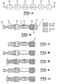
- Fig. 1a illustrates a sampling system 10 generally, showing a pump 11 for AC pumping, a separate pump 25 for DC pumping and a valve 15 to enable the switching from DC pumping to AC pumping.
- Pumps 11 and 25 and valve 15 all may be elements of the pump generically known as a mesopump, such as that described in commonly owned U.S. Patent No. 5,835,750 .
- a sensing device 23 connected to pump 11 through a buffer chamber 19 and a filter 21 that cleans the gas entering the sampling system during the purging phase of the operation cycle as disclosed below.
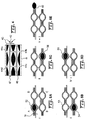
- Figs. 1b to 1f are schematic representations of the different phases of the operation cycle of the sampling system.
- Fig. 1b shows the purging phase of the operation.
- valve 15 is opened, allowing the gas to move from the purging port 27 to the sampling port 29.
- the gas filling the system from purging port 27 is cleaned by filter 21, serving as a reference gas for the following phases of the operation cycle.
- Fig. 1c shows the end of the purging phase.
- Valve 21 is closed, blocking the flow to and from the purging port 27.
- pump 11 can contribute to the pumping action by suitable synchronization with pump 25 or can be kept inactive, in a neutral position.
- Figs. 1b, 1d, 1e, 1f and 1g show the operation of the diaphragm pump with arrows indicating the induced air flow outside the system.
- a volume of gas equal to the pump chamber 17 and proportionally larger than the volume of sensing chamber 23 is expelled out of the system in pump 11b by movement of diaphragm 13 in pump chamber 17, downward in the drawing.
- Fig. 1d the base-line level and drift of the chemical sensor located in sampling chamber 23 are established as shown as phase d of Fig. 2 .
- Fig. le which is of course phase e of the cycle, wherein a fresh sample of analyte gas from the environment is brought into sampling chamber 23, functioning in the inhaling phase of the sniffing mode.
- Diaphragm 13 moves up with valve 15 closed, so sample air is drawn into sensor head 23.
- Buffer chamber 19 is used to prevent outside air from getting into pump chamber 17, thus avoiding contamination of the pump 11 with particles and with the analyte gas.
- the sensor in sampling chamber 23 will produce an output indicating the analyte concentration.
- Fig. If illustrates the exhaling phase of the sniffing system, where rapid movement of diaphragm 13, by electrostatic action for example, causes a jet-formation regime to expel everything from sensor head 23 to insure a fresh sample during the next intake phase.
- the action of diaphragm 13 pushes the sample out of the sensor head and fills the sampling chamber 23 again with the reference air from buffer chamber 19 and pump chamber 17.
- this phase shown as Fig. If, the reading from the sensor in sampling chamber 23 will correspond to the reference gas and is expected to be stable. Any variation in the output of the sensor during this phase will indicate base-line drift of the chemical sensor used in sensor head 23 as phase f of Fig. 2 .
- the cycle then begins again by inhaling another sample as shown in Fig 1g and phase g of Fig. 2 .
- the analyte may accumulate in the sensing device after a certain number of cycles or until a saturation level is detected.
- a purging cycle is initiated, as shown in Fig. 1b , where valve 15 is opened to permit DC cycle operation purging using purge pump 25 and filter 21.
- the dimensions of the device and flow rates conform to certain constraints.
- the flow pattern is highly irreversible.
- the flow in the sampling chamber 23 must be fast enough to provide sufficient momentum to the air so that it is expelled into the open space away from the sensor head.
- this air will not be drawn back into the sensor during an inhaling phase which brings in fresh analyte.
- the inhaled air comes from the near neighborhood of the sensor head and is therefore different and fresher than the exhaled air. This principle, though used by all breathing animals to avoid breathing in their own exhaled air, has not been used to date in active sampling systems.
- the sensing chamber 23 is small enough and the inhale phase, Fig. 1e , is of long enough duration that most of the analyte molecules diffuse to and absorb onto the sensing surface therein.
- the exhaling phase is fast enough and the sensing head opening is small enough to generate an exhaust jet with sufficient momentum to avoid being drawn in during the next inhale cycle.
- the air from the environment is retained in the sensor head 23 for a time long enough to diffuse to the walls but short enough to avoid diffusion into pump chamber 17.
- sampling chamber 23 would have a preferred volume of two microliters for each centimeter length of the chamber, such as 10 microliters for 5 centimeters of sampling chamber.
- Pump chamber 17 would have a volume of 3 microliters for a pump chamber with a 7.5 mm diameter, or 10 microliters for the 10 mm chamber. With these dimensions, mesopumps have functioned in the AC mode at a period of operation of 50 Hz.
- an AC mode flow at high frequency of about 20 Hz to 50 Hz, can be maintained for about ten seconds, resulting in a 2 ml total sample volume for the 10 mm chamber, followed by purging at a higher pump speed, such as 100 ml/min, achieved by using the purging pump.
- heaters may be used for the purging phase to assist in desorption.
- a heater may be placed in buffer chamber 19, for example, to accomplish this step.
- Output (1) illustrates the case where the analyte molecules have reacted irreversibly with the sensor material, so a dosimeter-type response is obtained.
- the chemical sensor output will increase during inhaling and will remain constant during exhaling, with the base-line monotonically increasing.
- the output of the chemical sensor will have a Fourier component at the sniffing frequency, proportional to the concentration of analyte but out of phase with the pumping action.
- Phase-sensitive detection or other means of correlating the pumping action with the sensor output allows the separation of the montonically increasing signal from the output, producing an output proportional to the analyte concentration. Without the active sniffing action, it would be very hard to distinguish between the analyte response and the base-line drift of the sensor. Output variations due to temperature changes, for example, will be much slower than the pumping action and can be subtracted by AC signal processing.
- Figs. 3a and 3b illustrate the intake mode and output mode of a single chamber diaphragm pump operating in the AC regime.
- Molded pump body 31 includes a port 32 for input in Fig. 3a and output in Fig. 3b , leading to a chamber 33 which is filled or emptied by movement of diaphragm 34 upon action of a driving signal from signal source 36 to create electrostatic forces on electrodes 37.
- Back pressure vent 38 is included in pump body 31 to facilitate movement of diaphragm 34 and elimination of back pressure.
- Pump body 31 is, of course, connected via port 32 to a sensing chamber 37.
- the dimensions and frequency of operation are chosen so that most of the analyte is absorbed during the inhaling cycle. The resulting clean air provides the referernce for the exhale cycle.
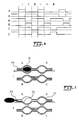
- Fig. 4 illustrates one mesopump channel 41, draws air into inlet 42 through filter 43, through chambers 44a, 44b, 44c and 44d to produce flow in the direction of arrow 46, for discharge via port 47.
- this mesopump which of course can be in an array, four chambers 44a-d operate electrostatically to move fluid through the sequence in the manner of mesopump operation.
- Fig. 7 Operation of the mesopump of Fig. 4 in the AC regime is shown in Fig. 7 , where pump 71 is operated with one diaphragm 73 operating to intake and exhale fluid at port 74, while diaphragms 75, 76 and 77, acting as valves, are kept in a fixed position to close the inter-chamber conduits.
- a first output occurs during exposure to the fresh sample of analyte gas, and the sensor can typically be read at a frequency much higher than the frequency of the sampling cycle.
- the sensor output will indicate the accumulation of analyte in the sensing layer during this phase of the sampling cycle.
- the sensor output during exposure to reference (cleaned) air will occur without analyte being attached to the sensing layer and the output of the sensor during this exposure to clean air should be stable or decrease as analyte is desorbed. If, however, an increase in the level of the analyte during exposure to clean air samples would be detected, this would indicate a drift in the base-line and could be accounted for in the measurement process.
- IR detection a chopper is used, and the IR sensor is alternately exposed to the shutter and to the IR source. It is commonly used to detect infrared radiation through the use of a mechanical chopper. In this example, the infrared imager alternately sees the scene and the chopper blade that presents it with a reference temperature.
- phase-sensitive detection methods the temperature of the chopper blade is subtracted from the temperature of the scene, providing a thermal image in which full contrast corresponds to a few degrees of temperature difference in the scene.
- the meso-sniffer of this invention has been discovered to function as the equivalent of a chopper blade to enable phase sensitive detection for a chemicl sensor.
- phase-sensitive detection provides two output signals instead of one: the in-phase and the out-of-phase components of teh signals.
- these two components provide information on the reversibiltiy of the chemical interaction between the analyte molecules and the material of the chemical sensor.
- the analyte molecules adsorbed during inhaling will be desorbed during the exhaling phase and the sensor output will be in phase with the pumping motion. See Fig. 2 , detector output (1).
- detector output (2) if the analyte molecules react irreversibly with the sensor material a dosimeter-type response is obtained, as in Fig. 2 , detector output (2).
- the chemical sensor output will increase during inhaling and wil remain constant during exhaling, with the baseline monitonically increasing.
- the output of the chemical sensor will have a Fourier component at the sniffing frequency, proportional to the concentration of analyte but out of phase with the pumping action. Phase-sensitived detection subtracts the monotonically increasing signal from the output, producing an output proportional to the analyte concentration as shown in Fig. 2 , detector output (3). Without the active sniffing action, it is very hard to distinguish the monotonic increase from baseline drift of the sensor. Output variations due to temperature changes, for example, will be much slower than the sniffing action and are much reduced by AC signal processing.
- phase-sensitive detection or equivalent signal processing methods significantly advances the state of the art of chemical sensing, since the present invention can be applied to many types of chemical sensors. This mode of operation is especially beneficial to the problem of land mine detection, where rapid detection of very low levels of explosives is needed.
Landscapes
- Chemical & Material Sciences (AREA)
- Life Sciences & Earth Sciences (AREA)
- Health & Medical Sciences (AREA)
- Engineering & Computer Science (AREA)
- Analytical Chemistry (AREA)
- General Physics & Mathematics (AREA)
- Pathology (AREA)
- Physics & Mathematics (AREA)
- Immunology (AREA)
- Biochemistry (AREA)
- General Health & Medical Sciences (AREA)
- Combustion & Propulsion (AREA)
- Food Science & Technology (AREA)
- Medicinal Chemistry (AREA)
- Biomedical Technology (AREA)
- Molecular Biology (AREA)
- Sampling And Sample Adjustment (AREA)
- Reciprocating Pumps (AREA)
Applications Claiming Priority (3)
| Application Number | Priority Date | Filing Date | Title |
|---|---|---|---|
| US09/430,425 US6432721B1 (en) | 1999-10-29 | 1999-10-29 | Meso sniffer: a device and method for active gas sampling using alternating flow |
| US430425 | 1999-10-29 | ||
| PCT/US2000/029435 WO2001030497A2 (en) | 1999-10-29 | 2000-10-26 | The meso sniffer: a device and method for active gas sampling using alternating flow |
Publications (2)
| Publication Number | Publication Date |
|---|---|
| EP1224458A2 EP1224458A2 (en) | 2002-07-24 |
| EP1224458B1 true EP1224458B1 (en) | 2009-11-18 |
Family
ID=23707507
Family Applications (1)
| Application Number | Title | Priority Date | Filing Date |
|---|---|---|---|
| EP00991851A Expired - Lifetime EP1224458B1 (en) | 1999-10-29 | 2000-10-26 | The meso sniffer: a device and method for active gas sampling using alternating flow |
Country Status (8)
| Country | Link |
|---|---|
| US (2) | US6432721B1 (enExample) |
| EP (1) | EP1224458B1 (enExample) |
| JP (1) | JP2003512632A (enExample) |
| AT (1) | ATE449328T1 (enExample) |
| AU (1) | AU3634101A (enExample) |
| CA (1) | CA2389338A1 (enExample) |
| DE (1) | DE60043353D1 (enExample) |
| WO (1) | WO2001030497A2 (enExample) |
Families Citing this family (28)
| Publication number | Priority date | Publication date | Assignee | Title |
|---|---|---|---|---|
| US6432721B1 (en) * | 1999-10-29 | 2002-08-13 | Honeywell International Inc. | Meso sniffer: a device and method for active gas sampling using alternating flow |
| DE19960174A1 (de) * | 1999-12-14 | 2001-06-28 | Leybold Vakuum Gmbh | Verfahren zur Lecksuche und Lecklokalisierung sowie zur Durchführung dieser Verfahren geeignete Vorrichtungen |
| US6568286B1 (en) * | 2000-06-02 | 2003-05-27 | Honeywell International Inc. | 3D array of integrated cells for the sampling and detection of air bound chemical and biological species |
| US7420659B1 (en) | 2000-06-02 | 2008-09-02 | Honeywell Interantional Inc. | Flow control system of a cartridge |
| US7061595B2 (en) * | 2000-08-02 | 2006-06-13 | Honeywell International Inc. | Miniaturized flow controller with closed loop regulation |
| US7465425B1 (en) * | 2002-09-09 | 2008-12-16 | Yizhong Sun | Sensor and method for detecting analytes in fluids |
| AU2003294535A1 (en) * | 2002-12-20 | 2004-07-14 | Fiso Technologies Inc. | Polarisation interferometric method and sensor for detecting a chemical substance |
| US20050084893A1 (en) * | 2003-10-16 | 2005-04-21 | Smiths Detection Inc. | Automated bioaerosol analysis platform |
| US7168675B2 (en) * | 2004-12-21 | 2007-01-30 | Honeywell International Inc. | Media isolated electrostatically actuated valve |
| US20060134510A1 (en) * | 2004-12-21 | 2006-06-22 | Cleopatra Cabuz | Air cell air flow control system and method |
| US7216048B2 (en) * | 2004-12-30 | 2007-05-08 | Honeywell International Inc. | Calibrated pressure sensor |
| US7328882B2 (en) | 2005-01-06 | 2008-02-12 | Honeywell International Inc. | Microfluidic modulating valve |
| US7445017B2 (en) * | 2005-01-28 | 2008-11-04 | Honeywell International Inc. | Mesovalve modulator |
| US7654129B2 (en) * | 2005-05-17 | 2010-02-02 | Honeywell International Inc. | Sensor with an analyte modulator |
| US7320338B2 (en) * | 2005-06-03 | 2008-01-22 | Honeywell International Inc. | Microvalve package assembly |
| US7517201B2 (en) | 2005-07-14 | 2009-04-14 | Honeywell International Inc. | Asymmetric dual diaphragm pump |
| US20070045128A1 (en) * | 2005-08-19 | 2007-03-01 | Honeywell International Inc. | Chlorine dioxide sensor |
| US20070051415A1 (en) * | 2005-09-07 | 2007-03-08 | Honeywell International Inc. | Microvalve switching array |
| US8549934B2 (en) * | 2008-03-25 | 2013-10-08 | Flownamics Analytical Instruments, Inc. | Segmented online sampling apparatus and method of use |
| DE102008024769B4 (de) | 2008-05-23 | 2014-01-30 | Eads Deutschland Gmbh | Vorrichtung und Verfahren zum Erfassen von Spurengasen |
| US10282965B2 (en) * | 2014-12-11 | 2019-05-07 | Intel Corporation | Synthetic jet delivering controlled flow to sensor system |
| WO2016183016A1 (en) | 2015-05-08 | 2016-11-17 | Flownamics Analytical Instruments, Inc. | Method & apparatus for continuous automated perfusion system harvesting from in-situ filtration probe |
| JP6651753B2 (ja) * | 2015-09-09 | 2020-02-19 | 富士電機株式会社 | 微粒子組成分析装置 |
| EP3479114B1 (de) * | 2016-07-04 | 2020-08-19 | Fraunhofer Gesellschaft zur Förderung der angewandten Forschung E.V. | Gerät mit mikrofluidaktor |
| US10302599B2 (en) * | 2016-10-27 | 2019-05-28 | Infineon Technologies Ag | Photoacoustic gas detector |
| WO2018191703A1 (en) | 2017-04-14 | 2018-10-18 | Johnson Controls Technology Company | Thermostat with preemptive heating, cooling, and ventilation in response to elevated occupancy detection via proxy |
| EP3527826B1 (en) * | 2018-02-16 | 2020-07-08 | ams AG | Pumping structure, particle detector and method for pumping |
| CN110457296B (zh) * | 2019-07-05 | 2021-12-03 | 中国船舶重工集团公司第七一九研究所 | 一种定速泵运行数据的清洗方法 |
Family Cites Families (26)
| Publication number | Priority date | Publication date | Assignee | Title |
|---|---|---|---|---|
| CH579418A5 (en) | 1974-06-12 | 1976-09-15 | Sicpa Int Sa | Pumping and mixing liquids with single pump - using three way valves and jet mixer with rotating arms |
| JPS5681451A (en) * | 1979-12-07 | 1981-07-03 | Olympus Optical Co Ltd | Separately-injecting nozzle |
| US4478096A (en) * | 1983-06-29 | 1984-10-23 | The United States Of America As Represented By The Secretary Of Agriculture | Shielded sniffing device |
| US5158868A (en) * | 1987-07-17 | 1992-10-27 | Iniziative Marittime 1991, S.R.L. | Method of sample analysis |
| US4997627A (en) * | 1987-07-17 | 1991-03-05 | Fisher Scientific Company | Sample analysis |
| US4920263A (en) * | 1988-01-26 | 1990-04-24 | Gemini Research, Inc. | Radon detection system |
| US4947339A (en) | 1988-12-01 | 1990-08-07 | Jan Czekajewski | Method and apparatus for measuring respiration, oxidation and similar interacting between a sample and a selected component of a fluid medium |
| US5133937A (en) * | 1989-06-01 | 1992-07-28 | Iniziative Marittime, 1991 S.R.L. | Analysis system having a removable reaction cartridge and temperature control |
| DE3925749C1 (enExample) | 1989-08-03 | 1990-10-31 | Fraunhofer-Gesellschaft Zur Foerderung Der Angewandten Forschung Ev, 8000 Muenchen, De | |
| SE508435C2 (sv) | 1993-02-23 | 1998-10-05 | Erik Stemme | Förträngningspump av membranpumptyp |
| US5659171A (en) * | 1993-09-22 | 1997-08-19 | Northrop Grumman Corporation | Micro-miniature diaphragm pump for the low pressure pumping of gases |
| US5758823A (en) * | 1995-06-12 | 1998-06-02 | Georgia Tech Research Corporation | Synthetic jet actuator and applications thereof |
| US5875823A (en) * | 1995-08-22 | 1999-03-02 | National Safety Advisors Inc. | Siphoning device for use in basting, measuring or immiscible liquid separation |
| DE69717075T2 (de) | 1996-02-09 | 2003-07-24 | Westonbridge International Ltd., Wellington Quay | Mikropumpe mit einem mikrobearbeiteten filter |
| US5900216A (en) * | 1996-06-19 | 1999-05-04 | Earth Resources Corporation | Venturi reactor and scrubber with suckback prevention |
| KR100210224B1 (ko) | 1996-07-03 | 1999-07-15 | 김성철 | 다이어프램 펌프 |
| US5720330A (en) * | 1997-01-23 | 1998-02-24 | Schmalz, Jr.; John W. | Squeeze bulb for liquid extraction device |
| US6037592A (en) * | 1997-02-14 | 2000-03-14 | Underground Systems, Inc. | System for measuring gases dissolved in a liquid |
| NL1006211C2 (nl) * | 1997-06-03 | 1998-12-04 | Applikon B V | Analyse-inrichting. |
| US6082185A (en) * | 1997-07-25 | 2000-07-04 | Research International, Inc. | Disposable fluidic circuit cards |
| US5836750A (en) | 1997-10-09 | 1998-11-17 | Honeywell Inc. | Electrostatically actuated mesopump having a plurality of elementary cells |
| US6085576A (en) * | 1998-03-20 | 2000-07-11 | Cyrano Sciences, Inc. | Handheld sensing apparatus |
| US6179586B1 (en) * | 1999-09-15 | 2001-01-30 | Honeywell International Inc. | Dual diaphragm, single chamber mesopump |
| US6432721B1 (en) * | 1999-10-29 | 2002-08-13 | Honeywell International Inc. | Meso sniffer: a device and method for active gas sampling using alternating flow |
| US6703241B1 (en) * | 1999-11-15 | 2004-03-09 | Cyrano Sciences, Inc. | Referencing and rapid sampling in artificial olfactometry |
| US6568286B1 (en) * | 2000-06-02 | 2003-05-27 | Honeywell International Inc. | 3D array of integrated cells for the sampling and detection of air bound chemical and biological species |
-
1999
- 1999-10-29 US US09/430,425 patent/US6432721B1/en not_active Expired - Lifetime
-
2000
- 2000-10-26 CA CA002389338A patent/CA2389338A1/en not_active Abandoned
- 2000-10-26 AU AU36341/01A patent/AU3634101A/en not_active Abandoned
- 2000-10-26 DE DE60043353T patent/DE60043353D1/de not_active Expired - Lifetime
- 2000-10-26 AT AT00991851T patent/ATE449328T1/de not_active IP Right Cessation
- 2000-10-26 WO PCT/US2000/029435 patent/WO2001030497A2/en not_active Ceased
- 2000-10-26 EP EP00991851A patent/EP1224458B1/en not_active Expired - Lifetime
- 2000-10-26 JP JP2001532902A patent/JP2003512632A/ja active Pending
-
2002
- 2002-04-02 US US10/115,305 patent/US7197949B2/en not_active Expired - Fee Related
Also Published As
| Publication number | Publication date |
|---|---|
| US7197949B2 (en) | 2007-04-03 |
| EP1224458A2 (en) | 2002-07-24 |
| WO2001030497A3 (en) | 2002-01-17 |
| CA2389338A1 (en) | 2001-05-03 |
| ATE449328T1 (de) | 2009-12-15 |
| JP2003512632A (ja) | 2003-04-02 |
| WO2001030497A2 (en) | 2001-05-03 |
| US6432721B1 (en) | 2002-08-13 |
| DE60043353D1 (de) | 2009-12-31 |
| US20030186462A1 (en) | 2003-10-02 |
| AU3634101A (en) | 2001-05-08 |
Similar Documents
| Publication | Publication Date | Title |
|---|---|---|
| EP1224458B1 (en) | The meso sniffer: a device and method for active gas sampling using alternating flow | |
| US6889567B2 (en) | 3D array integrated cells for the sampling and detection of air bound chemical and biological species | |
| EP2102628B1 (en) | Gas sensor with an analyte modulator | |
| CN101441143B (zh) | 移动采集化学分析用大气样品的装置 | |
| US9658196B2 (en) | Gas collection and analysis system with front-end and back-end pre-concentrators and moisture removal | |
| US6455003B1 (en) | Preconcentrator for chemical detection | |
| US8721892B2 (en) | Integrated chromatography devices and systems for monitoring analytes in real time and methods for manufacturing the same | |
| CN101128728B (zh) | 用于化学分析的大气样品移动收集设备和方法 | |
| US6656738B1 (en) | Internal heater for preconcentrator | |
| EP1440309B1 (en) | Ram-air sample collection device for a chemical warfare agent sensor | |
| JPH09506284A (ja) | 流体分析用測定装置 | |
| CA2391452A1 (en) | Apparatus and method for collecting and detecting chemicals | |
| US3509771A (en) | Breath sampling apparatus | |
| AU2665999A (en) | A valveless gas chromatographic system with pulsed injection and temperature programmed elution | |
| JP4225545B2 (ja) | マスタード検出装置 | |
| JP4172779B2 (ja) | ルイサイト検出装置 |
Legal Events
| Date | Code | Title | Description |
|---|---|---|---|
| PUAI | Public reference made under article 153(3) epc to a published international application that has entered the european phase |
Free format text: ORIGINAL CODE: 0009012 |
|
| 17P | Request for examination filed |
Effective date: 20020425 |
|
| AK | Designated contracting states |
Kind code of ref document: A2 Designated state(s): AT BE CH CY DE DK ES FI FR GB GR IE IT LI LU MC NL PT SE |
|
| AX | Request for extension of the european patent |
Free format text: AL;LT;LV;MK;RO;SI |
|
| 17Q | First examination report despatched |
Effective date: 20061218 |
|
| GRAP | Despatch of communication of intention to grant a patent |
Free format text: ORIGINAL CODE: EPIDOSNIGR1 |
|
| GRAS | Grant fee paid |
Free format text: ORIGINAL CODE: EPIDOSNIGR3 |
|
| GRAA | (expected) grant |
Free format text: ORIGINAL CODE: 0009210 |
|
| AK | Designated contracting states |
Kind code of ref document: B1 Designated state(s): AT BE CH CY DE DK ES FI FR GB GR IE IT LI LU MC NL PT SE |
|
| REG | Reference to a national code |
Ref country code: GB Ref legal event code: FG4D |
|
| REG | Reference to a national code |
Ref country code: CH Ref legal event code: EP |
|
| REG | Reference to a national code |
Ref country code: IE Ref legal event code: FG4D |
|
| REF | Corresponds to: |
Ref document number: 60043353 Country of ref document: DE Date of ref document: 20091231 Kind code of ref document: P |
|
| REG | Reference to a national code |
Ref country code: NL Ref legal event code: VDEP Effective date: 20091118 |
|
| PG25 | Lapsed in a contracting state [announced via postgrant information from national office to epo] |
Ref country code: FI Free format text: LAPSE BECAUSE OF FAILURE TO SUBMIT A TRANSLATION OF THE DESCRIPTION OR TO PAY THE FEE WITHIN THE PRESCRIBED TIME-LIMIT Effective date: 20091118 Ref country code: SE Free format text: LAPSE BECAUSE OF FAILURE TO SUBMIT A TRANSLATION OF THE DESCRIPTION OR TO PAY THE FEE WITHIN THE PRESCRIBED TIME-LIMIT Effective date: 20091118 Ref country code: ES Free format text: LAPSE BECAUSE OF FAILURE TO SUBMIT A TRANSLATION OF THE DESCRIPTION OR TO PAY THE FEE WITHIN THE PRESCRIBED TIME-LIMIT Effective date: 20100228 Ref country code: PT Free format text: LAPSE BECAUSE OF FAILURE TO SUBMIT A TRANSLATION OF THE DESCRIPTION OR TO PAY THE FEE WITHIN THE PRESCRIBED TIME-LIMIT Effective date: 20100318 |
|
| PG25 | Lapsed in a contracting state [announced via postgrant information from national office to epo] |
Ref country code: CY Free format text: LAPSE BECAUSE OF FAILURE TO SUBMIT A TRANSLATION OF THE DESCRIPTION OR TO PAY THE FEE WITHIN THE PRESCRIBED TIME-LIMIT Effective date: 20091118 |
|
| PG25 | Lapsed in a contracting state [announced via postgrant information from national office to epo] |
Ref country code: BE Free format text: LAPSE BECAUSE OF FAILURE TO SUBMIT A TRANSLATION OF THE DESCRIPTION OR TO PAY THE FEE WITHIN THE PRESCRIBED TIME-LIMIT Effective date: 20091118 Ref country code: AT Free format text: LAPSE BECAUSE OF FAILURE TO SUBMIT A TRANSLATION OF THE DESCRIPTION OR TO PAY THE FEE WITHIN THE PRESCRIBED TIME-LIMIT Effective date: 20091118 |
|
| PG25 | Lapsed in a contracting state [announced via postgrant information from national office to epo] |
Ref country code: DK Free format text: LAPSE BECAUSE OF FAILURE TO SUBMIT A TRANSLATION OF THE DESCRIPTION OR TO PAY THE FEE WITHIN THE PRESCRIBED TIME-LIMIT Effective date: 20091118 Ref country code: NL Free format text: LAPSE BECAUSE OF FAILURE TO SUBMIT A TRANSLATION OF THE DESCRIPTION OR TO PAY THE FEE WITHIN THE PRESCRIBED TIME-LIMIT Effective date: 20091118 |
|
| PLBE | No opposition filed within time limit |
Free format text: ORIGINAL CODE: 0009261 |
|
| STAA | Information on the status of an ep patent application or granted ep patent |
Free format text: STATUS: NO OPPOSITION FILED WITHIN TIME LIMIT |
|
| 26N | No opposition filed |
Effective date: 20100819 |
|
| PG25 | Lapsed in a contracting state [announced via postgrant information from national office to epo] |
Ref country code: GR Free format text: LAPSE BECAUSE OF FAILURE TO SUBMIT A TRANSLATION OF THE DESCRIPTION OR TO PAY THE FEE WITHIN THE PRESCRIBED TIME-LIMIT Effective date: 20100219 |
|
| PG25 | Lapsed in a contracting state [announced via postgrant information from national office to epo] |
Ref country code: IT Free format text: LAPSE BECAUSE OF FAILURE TO SUBMIT A TRANSLATION OF THE DESCRIPTION OR TO PAY THE FEE WITHIN THE PRESCRIBED TIME-LIMIT Effective date: 20091118 |
|
| PG25 | Lapsed in a contracting state [announced via postgrant information from national office to epo] |
Ref country code: MC Free format text: LAPSE BECAUSE OF NON-PAYMENT OF DUE FEES Effective date: 20101031 |
|
| REG | Reference to a national code |
Ref country code: CH Ref legal event code: PL |
|
| GBPC | Gb: european patent ceased through non-payment of renewal fee |
Effective date: 20101026 |
|
| PG25 | Lapsed in a contracting state [announced via postgrant information from national office to epo] |
Ref country code: LI Free format text: LAPSE BECAUSE OF NON-PAYMENT OF DUE FEES Effective date: 20101031 Ref country code: CH Free format text: LAPSE BECAUSE OF NON-PAYMENT OF DUE FEES Effective date: 20101031 |
|
| PG25 | Lapsed in a contracting state [announced via postgrant information from national office to epo] |
Ref country code: GB Free format text: LAPSE BECAUSE OF NON-PAYMENT OF DUE FEES Effective date: 20101026 |
|
| PG25 | Lapsed in a contracting state [announced via postgrant information from national office to epo] |
Ref country code: IE Free format text: LAPSE BECAUSE OF NON-PAYMENT OF DUE FEES Effective date: 20101026 |
|
| PG25 | Lapsed in a contracting state [announced via postgrant information from national office to epo] |
Ref country code: LU Free format text: LAPSE BECAUSE OF NON-PAYMENT OF DUE FEES Effective date: 20101026 |
|
| REG | Reference to a national code |
Ref country code: FR Ref legal event code: PLFP Year of fee payment: 17 |
|
| REG | Reference to a national code |
Ref country code: FR Ref legal event code: PLFP Year of fee payment: 18 |
|
| PGFP | Annual fee paid to national office [announced via postgrant information from national office to epo] |
Ref country code: FR Payment date: 20171031 Year of fee payment: 18 |
|
| PGFP | Annual fee paid to national office [announced via postgrant information from national office to epo] |
Ref country code: DE Payment date: 20171229 Year of fee payment: 18 |
|
| REG | Reference to a national code |
Ref country code: DE Ref legal event code: R119 Ref document number: 60043353 Country of ref document: DE |
|
| PG25 | Lapsed in a contracting state [announced via postgrant information from national office to epo] |
Ref country code: DE Free format text: LAPSE BECAUSE OF NON-PAYMENT OF DUE FEES Effective date: 20190501 |
|
| PG25 | Lapsed in a contracting state [announced via postgrant information from national office to epo] |
Ref country code: FR Free format text: LAPSE BECAUSE OF NON-PAYMENT OF DUE FEES Effective date: 20181031 |