EP1224366B1 - Joint bridging device - Google Patents
Joint bridging device Download PDFInfo
- Publication number
- EP1224366B1 EP1224366B1 EP00975913A EP00975913A EP1224366B1 EP 1224366 B1 EP1224366 B1 EP 1224366B1 EP 00975913 A EP00975913 A EP 00975913A EP 00975913 A EP00975913 A EP 00975913A EP 1224366 B1 EP1224366 B1 EP 1224366B1
- Authority
- EP
- European Patent Office
- Prior art keywords
- joint
- profile
- legs
- arrangement according
- bridging arrangement
- Prior art date
- Legal status (The legal status is an assumption and is not a legal conclusion. Google has not performed a legal analysis and makes no representation as to the accuracy of the status listed.)
- Expired - Lifetime
Links
Images


Classifications
-
- E—FIXED CONSTRUCTIONS
- E04—BUILDING
- E04F—FINISHING WORK ON BUILDINGS, e.g. STAIRS, FLOORS
- E04F19/00—Other details of constructional parts for finishing work on buildings
- E04F19/02—Borders; Finishing strips, e.g. beadings; Light coves
- E04F19/06—Borders; Finishing strips, e.g. beadings; Light coves specially designed for securing panels or masking the edges of wall- or floor-covering elements
- E04F19/065—Finishing profiles with a T-shaped cross-section or the like
- E04F19/067—Finishing profiles with a T-shaped cross-section or the like with means preventing a tipping movement
-
- E—FIXED CONSTRUCTIONS
- E04—BUILDING
- E04F—FINISHING WORK ON BUILDINGS, e.g. STAIRS, FLOORS
- E04F19/00—Other details of constructional parts for finishing work on buildings
- E04F19/02—Borders; Finishing strips, e.g. beadings; Light coves
- E04F19/06—Borders; Finishing strips, e.g. beadings; Light coves specially designed for securing panels or masking the edges of wall- or floor-covering elements
- E04F19/062—Borders; Finishing strips, e.g. beadings; Light coves specially designed for securing panels or masking the edges of wall- or floor-covering elements used between similar elements
-
- E—FIXED CONSTRUCTIONS
- E04—BUILDING
- E04F—FINISHING WORK ON BUILDINGS, e.g. STAIRS, FLOORS
- E04F19/00—Other details of constructional parts for finishing work on buildings
- E04F19/02—Borders; Finishing strips, e.g. beadings; Light coves
- E04F19/06—Borders; Finishing strips, e.g. beadings; Light coves specially designed for securing panels or masking the edges of wall- or floor-covering elements
- E04F19/065—Finishing profiles with a T-shaped cross-section or the like
- E04F19/066—Finishing profiles with a T-shaped cross-section or the like fixed onto a base profile by means of a separate connector
Definitions
- the invention relates to a joint bridging arrangement for a floor, in particular for bridging a joint in a parquet floor with different heights opposite joint edges according to the preamble of Claim 1.
- the invention is therefore based on the object of a joint bridging arrangement of the type described above create one in terms of height adjustability has expanded scope.
- the invention encompasses the general technical teaching that Not to attach the cover profile directly to the base profile, but between the base profile and the cover profile Arrange intermediate part.
- the intermediate part is preferably stackable so that the scope in terms of height adjustability Almost any number of intermediate parts can be expanded as required.
- the intermediate part on its underside two legs arranged side by side on the upstanding leg of the base profile reach around to the side.
- the intermediate part points to the top on the other hand preferably on one leg of two arranged on the underside of the cover profile Thighs are gripped laterally to provide a side guide guarantee.
- the attachment of the cover profile to the intermediate part or the attachment of the intermediate part to the base profile can are done in different ways.
- the intermediate part on the base profile screwed tight being in the upstanding leg the base profile is preferably a threaded drive channel Socket for the screw is provided.
- Socket for the screw
- the attachment of the cover profile on the intermediate part by a screw connection or Latching.
- the present invention is in terms of its application not limited to floor joints, but can be done in general use to bridge joints, with the Joint bridging arrangement according to the invention is particularly advantageous suitable for bridging joints in parquet floors.
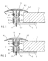
- the cross-sectional representation of a preferred embodiment of the joint bridging arrangement according to the invention is preferably used for bridging of joints in a parquet floor 1, the parquet floor 1 for simplicity only on one side the fugue is shown.
- Joint bridging arrangement on a base profile 2 the by a screw 3 shown only schematically on the Floor is screwed.
- the basic profile 2 is essentially L-shaped and has two legs 4.1 and 4.2 on that from the base plate of the base profile 2 so protrude at right angles into the joint, whereby the two legs 4.1 and 4.2 in the longitudinal direction in extend substantially over the entire length of the joint.
- joint bridging arrangement according to the invention 1, a cover profile 5 with two cover wings 6.1 and 6.2, with the two cover wings 6.1 and 6.2 rest on both sides of the joint on the parquet floor 1.
- an intermediate part 7 is arranged, the Scope regarding the height adjustability of the joint bridging arrangement compared to those described at the beginning known joint bridging arrangements expanded. So points the intermediate part 7 on its underside two legs 8.1 and 8.2 on, the two legs in the assembled state 4.1 and 4.2 of the base profile 2 reach around the outside and thereby a lateral guide of the intermediate part 2 relative to effect the basic profile 2. In addition, the intermediate part on its top two legs 9.1 and 9.2 on that on the outside of two at the bottom of the Cover profile 5 arranged legs 10.1 and 10.2 encompassed so that the leg pairs 9.1, 10.1 or 9.2, 10.2 a side guide of the cover profile 5 relative to effect the intermediate part 7.
- the fastening of the cover profile 5 and the intermediate part 7 on the base profile 2 is carried out by a screw 11 through appropriate holes in the cover profile 5 and Intermediate part 7 is introduced.
- the scope for height adjustability is further expanded be vertical by several intermediate parts 7 stacked on top of each other. That of the two legs 8.1 and 8.2 of the intermediate part included clear width therefore essentially equal to the outside width of the two Legs 9.1 and 9.2 of the intermediate part 7 to make them stackable to ensure.
- a major difference from that shown in Figure 2 Joint bridging arrangement compared to that shown in Figure 1 Joint bridging arrangement is that the Attachment of the cover profile 5 to the intermediate part 7 is not by a screw connection, but by locking. In this embodiment, this is on the underside of the cover profile 5 a leg 12 is formed, the also has a detent on both sides, the in the assembled state in the locking of the legs 9.1 and 9.2 of the intermediate part engages.
- the intermediate part 7 For fastening the intermediate part 7 to the base profile 2 has the intermediate part 7 in this embodiment on it Bottom of a single leg 13 on the Lateral surfaces along the joint a detent is attached.
- the two upstanding legs 4.1, 4.2 of the base profile 2 wear on the inside along the Add a notch in which the notch of the leg 13 engages, and the intermediate part 7 thus vertical fixed.
- the joint bridging arrangement according to Figure 3 enables advantageous assembly without tools, since the attachment only by locking.
- the intermediate part 7 points accordingly two legs 15.1 and 15.2 arranged side by side, while at the top of the base plate of the base profile 2 a leg 16 projecting upward at right angles is formed is that in the assembled state of the two legs 15.1 and 15.2 of the intermediate part 7 is gripped laterally and thereby a lateral guide of the intermediate part 7 relative to the base profile 2.
- the on the inside of the legs 15.1, 15.2 and on the outside of the leg 16 arranged detents a vertical Fixing the intermediate part 7 relative to the base profile Second
- cover profile 5 is attached to the Base profile 2 also with a screw connection.
- the peculiarity of the embodiment shown in Figure 6 is that for the connection of the cover profile 5 with the intermediate part 7 and for fastening the A separate part 7 on the base profile 2 Screw 18, 19 is provided.
- the base profile 2 is first replaced by a only schematically illustrated screw 3 on the floor screwed.
- the intermediate part 7 is on the base profile 2 placed that the two legs projecting downwards 8.1, 8.2 of the intermediate part 7, the two projecting upwards Grip legs 4.1, 4.2 of base profile 2 laterally.
- the screw 19 is then replaced by a screw in the intermediate part 7 centrally arranged bore passed through the two legs 4.1, 4.2 of the base profile 2 have a threaded bore (The tapped hole can also be through a threaded drive channel be formed) for the screw 19.
- the screw 19 is then corresponding to that to be bridged Height difference and the thickness of the floor covering 1 attracted.
- the screw 19 can only be slightly tightened, so that the legs 4.1, 4.2 of the base profile 2 are not on the intermediate part 7, just a side guide cause. With a thin floor covering 1 Screw 19, however, may be tightened so far that the legs 4.1, 4.2 of the base profile 2 at the top of the intermediate part Strike 7.
- the cover profile 5 will be like this placed on the intermediate part 7 that the legs 10.1, 10.2 of the cover profile 5, the legs 9.1, 9.2 of the intermediate part 7 reach around the side.
- the second screw 18 by a mounted in the cover profile 5 Countersunk hole inserted, with the upstanding Legs 9.1, 9.2 of the intermediate part 7 a threaded bore (The tapped hole can also be through a threaded drive channel be formed) for the second screw 18.
- the Screw 18 is then tightened until the cover wing 6.2 of the cover profile 5 with the desired tension lies on the floor covering.
Abstract
Description
Die Erfindung betrifft eine Fugenüberbrückungsanordnung für
einen Fußboden, insbesondere zur Überbrückung einer Fuge in
einem Parkettfußboden mit unterschiedlicher Höhenlage der
gegenüberliegenden Fugenränder gemäß dem Oberbegriff des
Anspruchs 1.The invention relates to a joint bridging arrangement for
a floor, in particular for bridging a joint in
a parquet floor with different heights
opposite joint edges according to the preamble of
Aus der europäischen Patentschrift EP 0 321 634 B1 ist eine derartige Fugenüberbrückungsanordnung bekannt, die aus einem L-förmigen Basisprofil und einem an dem Basisprofil befestigten Abdeckprofil besteht. Das Basisprofil wird hierbei durch eine Verschraubung an dem Fußboden befestigt, wobei der eine Schenkel des L-förmigen Basisprofils nach oben in die Fuge hineinragt. Das Abdeckprofil überdeckt hierbei die Fuge und weist zwei nach unten in die Fuge hineinragende Schenkel auf, die den Schenkel des L-förmigen Profils seitlich umgreifen und dadurch eine Seitenführung des Abdeckprofils bewirken. Die Befestigung des Abdeckprofils an dem Basisprofil erfolgt durch eine Schraube, die durch eine Bohrung in dem Abdeckprofil in einen Gewindetreibkanal eingeschraubt wird, der in dem nach oben in die Fuge hineinragenden Schenkel des Basisprofils angeordnet ist. Die vorstehend beschriebene bekannte Fugenüberbrückungsanordnung ermöglicht vorteilhaft eine Überbrückung von Fugen unterschiedlicher Tiefe, da die beiden Schenkel des Abdeckprofils unabhängig von der Höhenlage des Abdeckprofils eine Seitenführung bewirken.From European patent specification EP 0 321 634 B1 is one such joint bridging arrangement is known, which from a L-shaped base profile and one attached to the base profile Cover profile exists. The basic profile is here attached to the floor by a screw connection, whereby one leg of the L-shaped base profile upwards protrudes into the joint. The cover profile covers this the joint and has two protruding downwards into the joint Thighs on the thigh of the L-shaped profile reach around the side and thereby a side guide of the cover profile cause. The fastening of the cover profile the base profile is done by a screw that by a Drilled hole in the cover profile in a threaded drive channel the one that protrudes upwards into the joint Leg of the base profile is arranged. The above known joint bridging arrangement described advantageously enables bridging of different joints Depth because the two legs of the cover profile regardless of the height of the cover profile Effect lateral guidance.
Nachteilig an der vorstehend beschriebenen bekannten Fugenüberbrückungsanordnung ist jedoch die Tatsache, daß hinsichtlich der Höhenverstellbarkeit der Fugenüberbrückungsanordnung nur ein relativ geringer Spielraum besteht, da die beiden Schenkel des Abdeckprofils den nach oben ragenden Schenkel des Basisprofils seitlich umfassen müssen, um eine Seitenführung zu gewährleisten.A disadvantage of the known joint bridging arrangement described above however, the fact is that the height adjustability of the joint bridging arrangement there is only relatively little scope because the two legs of the cover profile projecting upwards Legs of the base profile must include laterally to ensure lateral guidance.
Der Erfindung liegt somit die Aufgabe zugrunde, eine Fugenüberbrückungsanordnung der vorstehend beschriebenen Art zu schaffen, die hinsichtlich der Höhenverstellbarkeit einen erweiterten Spielraum aufweist.The invention is therefore based on the object of a joint bridging arrangement of the type described above create one in terms of height adjustability has expanded scope.
Diese Aufgabe wird, ausgehend von der vorstehend beschriebenen
bekannten Fugenüberbrückungsanordnung gemäß dem Oberbegriff
des Anspruchs 1, durch die kennzeichnenden Merkmale
des Anspruchs 1 gelöst.This task is based on that described above
known joint bridging arrangement according to the preamble
of
Die Erfindung umfaßt die allgemeine technische Lehre, das Abdeckprofil nicht direkt an dem Basisprofil zu befestigen, sondern zwischen dem Basisprofil und dem Abdeckprofil ein Zwischenteil anzuordnen.The invention encompasses the general technical teaching that Not to attach the cover profile directly to the base profile, but between the base profile and the cover profile Arrange intermediate part.
Vorzugsweise ist das Zwischenteil hierbei stapelbar, so daß der Spielraum hinsichtlich der Höhenverstellbarkeit durch Einsetzen einer beliebigen Anzahl von Zwischenteilen nahezu beliebig erweitert werden kann.The intermediate part is preferably stackable so that the scope in terms of height adjustability Almost any number of intermediate parts can be expanded as required.
In der bevorzugten Ausführungsform weist das Zwischenteil an seiner Unterseite zwei nebeneinander angeordnete Schenkel auf, die den nach oben ragenden Schenkel des Basisprofils seitlich umgreifen. An der Oberseite weist das Zwischenteil dagegen vorzugsweise einen Schenkel auf, der von zwei an der Unterseite des Abdeckprofils angeordneten Schenkeln seitlich umgriffen wird, um eine Seitenführung zu gewährleisten.In the preferred embodiment, the intermediate part on its underside two legs arranged side by side on the upstanding leg of the base profile reach around to the side. The intermediate part points to the top on the other hand preferably on one leg of two arranged on the underside of the cover profile Thighs are gripped laterally to provide a side guide guarantee.
Die Befestigung des Abdeckprofils an dem Zwischenteil bzw. die Befestigung des Zwischenteils an dem Basisprofil kann hierbei in verschiedener Weise erfolgen. In einer Variante der Erfindung wird das Zwischenteil an dem Basisprofil festgeschraubt, wobei in dem nach oben ragenden Schenkel des Basisprofils vorzugsweise ein Gewindetreibkanal als Fassung für die Schraube vorgesehen ist. Es ist jedoch auch möglich, an den aneinander anliegenden Schenkeln von Basisprofil und Zwischenteil Rastungen vorzusehen, so daß das Zwischenteil lediglich auf das Basisteil aufgedrückt werden muß. In gleicher Weise kann die Befestigung des Abdeckprofils an dem Zwischenteil durch eine Verschraubung oder eine Verrastung erfolgen. Neben den vorstehend beschriebenen Befestigungsarten sind selbstverständlich auch andere Befestigungsarten möglich, die dem Fachmann geläufig sind.The attachment of the cover profile to the intermediate part or the attachment of the intermediate part to the base profile can are done in different ways. In a variant the invention is the intermediate part on the base profile screwed tight, being in the upstanding leg the base profile is preferably a threaded drive channel Socket for the screw is provided. However, it is also possible on the adjacent legs of the base profile and intermediate part to provide detents, so that Intermediate part can only be pressed onto the base part got to. In the same way, the attachment of the cover profile on the intermediate part by a screw connection or Latching. In addition to the types of fastening described above are of course other types of fastening possible that are familiar to the expert.
Die vorliegende Erfindung ist hinsichtlich ihrer Anwendung nicht auf Fußbodenfugen beschränkt, sondern läßt sich allgemein zur Überbrückung von Fugen verwenden, wobei sich die erfindungsgemäße Fugenüberbrückungsanordnung besonders vorteilhaft zur Überbrückung von Fugen in Parkettfußböden eignet.The present invention is in terms of its application not limited to floor joints, but can be done in general use to bridge joints, with the Joint bridging arrangement according to the invention is particularly advantageous suitable for bridging joints in parquet floors.
Andere vorteilhafte Weiterbildungen der Erfindung sind in den Unteransprüchen gekennzeichnet bzw. werden nachstehend zusammen mit der Beschreibung der bevorzugten Ausführungsbeispiele der Erfindung anhand der Figuren näher dargestellt. Es zeigen:
Figur 1- eine Querschnittsdarstellung einer erfindungsgemäßen Fugenüberbrückungsanordnung mit einer Befestigung von Abdeckprofil, Zwischenteil und Basisprofil durch eine einzige Schraube,
Figur 2- eine Querschnittsdarstellung einer anderen Ausführungsform einer erfindungsgemäßen Fugenüberbrückungsanordnung, bei der das Zwischenteil an dem Basisprofil festgeschraubt wird, während das Abdeckprofil durch eine Verrastung an dem Zwischenteil befestigt ist,
Figur 3- eine Querschnittsdarstellung eines weiteren erfindungsgemäßen Ausführungsbeispiels, bei dem sämtliche Bauteile durch Verrastung miteinander verbunden sind,
Figur 4- ein anderes Ausführungsbeispiel mit einer gegenüber
Figur 3 umgekehrten Anordnung der Schenkel, Figur 5- ein erfindungsgemäßes Ausführungsbeispiel, bei dem das Zwischenteil durch eine Verrastung an dem Basisprofil befestigt ist, wohingegen das Abdeckprofil an dem Zwischenteil festgeschraubt ist sowie
- Figur 6
- ein erfindungsgemäßes Ausführungsbeispiel, bei dem das Abdeckprofil mit dem Zwischenteil verschraubt wird, während das Zwischenteil durch eine separate Schraube an dem Basisprofil festgeschraubt wird.
- Figure 1
- 2 shows a cross-sectional illustration of a joint bridging arrangement according to the invention with a fastening of the cover profile, intermediate part and base profile by means of a single screw,
- Figure 2
- 2 shows a cross-sectional representation of another embodiment of a joint bridging arrangement according to the invention, in which the intermediate part is screwed tightly to the base profile, while the cover profile is fastened to the intermediate part by means of a catch,
- Figure 3
- 2 shows a cross-sectional illustration of a further exemplary embodiment according to the invention, in which all components are connected to one another by latching,
- Figure 4
- another exemplary embodiment with a reverse arrangement of the legs compared to FIG. 3,
- Figure 5
- an embodiment according to the invention, in which the intermediate part is fastened to the base profile by a catch, whereas the cover profile is screwed to the intermediate part and
- Figure 6
- an embodiment of the invention, in which the cover profile is screwed to the intermediate part, while the intermediate part is screwed to the base profile by a separate screw.
Die in Figur 1 wiedergegebene Querschnittsdarstellung eines
bevorzugten Ausführungsbeispiels der erfindungsgemäßen Fugenüberbrückungsanordnung
dient vorzugsweise zur Überbrükkung
von Fugen in einem Parkettfußboden 1, wobei der Parkettfußboden
1 zur Vereinfachung lediglich auf einer Seite
der Fuge dargestellt ist. Zur Fixierung der Fugenüberbrükkungsanordnung
an dem Fußboden weist die erfindungsgemäße
Fugenüberbrückungsanordnung ein Basisprofil 2 auf, das
durch eine nur schematisch dargestellte Schraube 3 an dem
Fußboden festgeschraubt wird. Das Basisprofil 2 ist im wesentlichen
L-förmig ausgebildet und weist zwei Schenkel 4.1
und 4.2 auf, die von der Grundplatte des Basisprofils 2 so
rechtwinklig nach oben in die Fuge hinein abstehen, wobei
sich die beiden Schenkel 4.1 und 4.2 in Längsrichtung im
wesentlichen über die gesamte Länge der Fuge erstrecken.The cross-sectional representation of a
preferred embodiment of the joint bridging arrangement according to the invention
is preferably used for bridging
of joints in a
Weiterhin weist die erfindungsgemäße Fugenüberbrückungsanordnung
gemäß Figur 1 ein Abdeckprofil 5 mit zwei Abdeckflügeln
6.1 und 6.2 auf, wobei die beiden Abdeckflügel 6.1
und 6.2 beidseitig der Fuge auf dem Parkettfußboden 1 aufliegen.Furthermore, the joint bridging arrangement according to the
Wenn ein Abschlußprofil anstelle des gezeichneten Abdeckprofils eingesetzt wird, so liegt nur der eine Abdeckflügel auf dem Parkett- oder Laminatfußboden auf.If an end profile instead of the drawn cover profile only one cover wing is used on the parquet or laminate floor.
In vertikaler Richtung zwischen dem Abdeckprofil 5 und dem
Basisprofil 2 ist ein Zwischenteil 7 angeordnet, das den
Spielraum hinsichtlich der Höhenverstellbarkeit der Fugenüberbrückungsanordnung
gegenüber den eingangs beschriebenen
bekannten Fugenüberbrückungsanordnungen erweitert. So weist
das Zwischenteil 7 an seiner Unterseite zwei Schenkel 8.1
und 8.2 auf, die im montierten Zustand die beiden Schenkel
4.1 und 4.2 des Basisprofils 2 seitlich außen umgreifen und
dadurch eine Seitenführung des Zwischenteils 2 relativ zu
dem Basisprofil 2 bewirken. Darüber hinaus weist das Zwischenteil
an seiner Oberseite zwei Schenkel 9.1 und 9.2
auf, die an ihrer Außenseite von zwei an der Unterseite des
Abdeckprofils 5 angeordneten Schenkeln 10.1 und 10.2 umgriffen
werden, so daß die Schenkelpaare 9.1, 10.1 bzw.
9.2, 10.2 eine Seitenführung des Abdeckprofils 5 relativ zu
dem Zwischenteil 7 bewirken.In the vertical direction between the
Die Befestigung des Abdeckprofils 5 und des Zwischenteils 7
an dem Basisprofil 2 erfolgt durch eine Schraube 11, die
durch entsprechende Bohrungen in dem Abdeckprofil 5 und dem
Zwischenteil 7 eingeführt wird.The fastening of the
Bei dem vorstehend beschriebenen Ausführungsbeispiel der
erfindungsgemäßen Fugenüberbrückungsanordnung kann der
Spielraum hinsichtlich der Höhenverstellbarkeit weiter ausgedehnt
werden, indem mehrere Zwischenteile 7 vertikal
übereinander gestapelt werden. Die von den beiden Schenkeln
8.1 und 8.2 des Zwischenteils umfaßte lichte Breite ist
deshalb im wesentlichen gleich der Außenbreite der beiden
Schenkel 9.1 und 9.2 des Zwischenteils 7, um eine Stapelbarkeit
zu gewährleisten.In the embodiment of the
Joint bridging arrangement according to the invention can
The scope for height adjustability is further expanded
be vertical by several
Das in Figur 2 dargestellte Ausführungsbeispiel einer erfindungsgemäßen Fugenüberbrückungsanordnung stimmt weitgehend mit dem vorstehend beschriebenen und in Figur 1 dargestellten Ausführungsbeispiel überein, so daß im folgenden für übereinstimmende Bauteile dieselben Bezugszeichen verwendet werden und diesbezüglich zur Vermeidung von Wiederholungen auf die vorstehende Beschreibung verwiesen wird.The embodiment shown in Figure 2 of an inventive Joint bridging arrangement is largely correct with that described above and shown in Figure 1 Embodiment match, so that in the following the same reference numerals are used for matching components and in this regard to avoid repetitions reference is made to the above description.
Ein wesentlicher Unterschied der in Figur 2 dargestellten
Fugenüberbrückungsanordnung gegenüber der in Figur 1 dargestellten
Fugenüberbrückungsanordnung besteht darin, daß die
Befestigung des Abdeckprofils 5 an dem Zwischenteil 7 nicht
durch eine Verschraubung, sondern durch eine Verrastung erfolgt.
Hierzu ist bei diesem Ausführungsbeispiel an der Unterseite
des Abdeckprofils 5 ein Schenkel 12 angeformt, der
an seinen beiden Seitenflächen ebenfalls eine Rastung aufweist,
die im montierten Zustand in die Rastung der Schenkel
9.1 und 9.2 des Zwischenteils eingreift.A major difference from that shown in Figure 2
Joint bridging arrangement compared to that shown in Figure 1
Joint bridging arrangement is that the
Attachment of the
Die Befestigung des Zwischenteils 7 an dem Basisprofil 2
erfolgt jedoch in herkömmlicher und vorstehend beschriebener
Weise durch eine Schraube 11. Bei der Montage der erfindungsgemäßen
Fugenüberbrückungsanordnung wird also zunächst
das Zwischenteil 7 an dem Basisprofil 2 festgeschraubt,
was ohne das Abdeckprofil 5 einfach möglich ist.
Anschließend wird das Abdeckprofil 5 dann in einfacher Weise
auf das Zwischenteil 7 aufgedrückt.The attachment of the
Das in Figur 3 wiedergegebene Ausführungsbeispiel stimmt ebenfalls weitgehend mit den vorstehend beschriebenen Ausführungsbeispielen überein, so daß im folgenden ebenfalls dieselben Bezugszeichen verwendet werden und zur Vermeidung von Wiederholungen auf die vorstehende Beschreibung verwiesen wird.The embodiment shown in Figure 3 is correct also largely with the exemplary embodiments described above agree, so that in the following also the same reference numerals are used and to avoid of repetitions referred to the above description becomes.
Der Unterschied des in Figur 3 dargestellten Ausführungsbeispiels
gegenüber den vorstehend beschriebenen Ausführungsbeispielen
besteht im wesentlichen darin, daß die Befestigung
des Abdeckprofils 5, des Zwischenteils 7 und des
Basisprofils 2 aneinander ausschließlich durch Verrastungen
erfolgt. Die Befestigung des Abdeckprofils 5 an dem Zwischenteil
7 erfolgt hierbei in derselben Weise wie in Figur
2, so daß diesbezüglich auf die vorstehende Beschreibung
verwiesen wird.The difference of the embodiment shown in Figure 3
compared to the exemplary embodiments described above
consists essentially in that the attachment
the
Zur Befestigung des Zwischenteils 7 an dem Basisprofil 2
weist das Zwischenteil 7 in dieser Ausführungsform an seiner
Unterseite einen einzigen Schenkel 13 auf, an dessen
Seitenflächen entlang der Fuge eine Rastung angebracht ist.
Die beiden nach oben ragenden Schenkel 4.1, 4.2 des Basisprofils
2 tragen hierbei an ihrer Innenseite entlang der
Fuge ebenfalls eine Rastung, in die die Rastung des Schenkels
13 eingreift, und das Zwischenteil 7 somit vertikal
fixiert.For fastening the
Die Fugenüberbrückungsanordnung gemäß Figur 3 ermöglicht vorteilhaft eine Montage ohne Werkzeug, da die Befestigung ausschließlich durch Verrastung erfolgt.The joint bridging arrangement according to Figure 3 enables advantageous assembly without tools, since the attachment only by locking.
Das in Figur 4 dargestellte Ausführungsbeispiel einer erfindungsgemäßen Fugenüberbrückungsanordnung stimmt nahezu vollständig mit dem in Figur 3 wiedergegebenen Ausführungsbeispiel überein, so daß weitgehend auf die vorstehende Beschreibung verwiesen wird.The embodiment shown in Figure 4 of an inventive Joint bridging arrangement is almost correct completely with the embodiment shown in Figure 3 agree, so that largely on the above description is referred.
Der Unterschied des in Figur 4 dargestellten Ausführungsbeispiels
gegenüber dem in Figur 3 dargestellten Ausführungsbeispiel
besteht im wesentlichen darin, daß die Anordnung
der Schenkel geometrisch vertauscht ist. So weist das
Abdeckprofil 5 an seiner Unterseite die beiden Schenkel
10.1 und 10.2 auf, deren Innenseiten Rastungen tragen. An
der Oberseite des Zwischenteils 7 ist ein Schenkel 14 einstückig
angeformt, der im montierten Zustand von den beiden
Schenkeln 10.1 und 10.2 des Abdeckprofils 5 seitlich umgriffen
wird und ebenfalls Rastungen trägt, so daß das Abdeckprofil
5 durch die Verrastung vertikal zu dem Zwischenteil
7 fixiert wird.The difference of the embodiment shown in Figure 4
compared to the embodiment shown in Figure 3
consists essentially in that the arrangement
the leg is swapped geometrically. So that points
An seiner Unterseite weist das Zwischenteil 7 entsprechend
zwei nebeneinander angeordnete Schenkel 15.1 und 15.2 auf,
während an der Oberseite der Grundplatte des Basisprofils 2
ein rechtwinklig nach oben ragender Schenkel 16 angeformt
ist, der im montierten Zustand von den beiden Schenkeln
15.1 und 15.2 des Zwischenteils 7 seitlich umgriffen wird
und dadurch eine Seitenführung des Zwischenteils 7 relativ
zu dem Basisprofil 2 bewirkt. Darüber hinaus bewirken die
an der Innenseite der Schenkel 15.1, 15.2 und an der Außenseite
des Schenkels 16 angeordneten Rastungen eine vertikale
Fixierung des Zwischenteils 7 relativ zu dem Basisprofil
2.On its underside, the
Das in Figur 5 dargestellte Ausführungsbeispiel der erfindungsgemäßen Fugenüberbrückungsanordnung stimmt wiederum weitgehend mit dem in Figur 4 dargestellten Ausführungsbeispiel überein, so daß weitgehend auf die vorstehende Beschreibung verwiesen wird.The embodiment shown in Figure 5 of the invention Joint bridging arrangement is correct again largely with the embodiment shown in Figure 4 agree, so that largely on the above description is referred.
Ein wesentlicher Unterschied des in Figur 5 dargestellten
Ausführungsbeispiels gegenüber dem in Figur 4 dargestellten
Ausführungsbeispiel besteht darin, daß die Befestigung des
Abdeckprofils 5 an dem Zwischenteil 7 nicht durch eine Verrastung,
sondern durch eine Verschraubung erfolgt. Hierzu
ist in dem nach oben ragenden Schenkel 14 des Zwischenteils
7 ein Gewindetreibkanal angeordnet, in den eine Schraube 17
eingreift, die durch eine Bohrung in der Oberseite des Abdeckprofils
eingeführt wird.A major difference from that shown in Figure 5
Embodiment compared to that shown in Figure 4
Embodiment is that the attachment of the
Das in Figur 6 dargestellte Ausführungsbeispiel stimmt weitgehend mit dem vorstehend beschriebenen und in Figur 1 dargestellten Ausführungsbeispiel überein, so daß im folgenden dieselben Bezugszeichen verwendet werden und zur Vermeidung von Wiederholungen auf die vorstehende Beschreibung verwiesen wird.The embodiment shown in Figure 6 is correct largely with that described above and in FIG. 1 illustrated embodiment, so that in the following the same reference numerals are used and for Avoid repetition on the description above is referred.
Hierbei erfolgt die Befestigung des Abdeckprofils 5 an dem
Basisprofil 2 ebenfalls durch eine Verschraubung. Die Besonderheit
des in Figur 6 dargestellten Ausführungsbeispiels
besteht darin, daß für die Verbindung des Abdeckprofils
5 mit dem Zwischenteil 7 und für die Befestigung des
Zwischenteils 7 an dem Basisprofil 2 jeweils eine separate
Schraube 18, 19 vorgesehen ist.Here, the
Bei der Montage wird zunächst das Basisprofil 2 durch eine
nur schematisch dargestellte Schraube 3 an dem Fußboden
festgeschraubt.During assembly, the
Anschließend wird das Zwischenteil 7 so auf das Basisprofil
2 aufgesetzt, daß die beiden nach unten ragenden Schenkel
8.1, 8.2 des Zwischenteils 7 die beiden nach oben ragenden
Schenkel 4.1, 4.2 des Basisprofils 2 seitlich umgreifen.
Darauf hin wird die Schraube 19 durch eine in dem Zwischenteil
7 zentrisch angeordnete Bohrung hindurchgeführt, wobei
die beiden Schenkel 4.1, 4.2 des Basisprofils 2 eine Gewindebohrung
(die Gewindebohrung kann auch durch einen Gewindetreibkanal
ausgebildet sein) für die Schraube 19 bilden.
Die Schraube 19 wird dann entsprechend dem zu überbrückenden
Höhenunterschied und der Dicke des Fußbodenbelags 1 angezogen.
Ist der Fußbodenbelag 1 beispielsweise sehr dick,
so kann die Schraube 19 nur geringfügig angezogen, so daß
die Schenkel 4.1, 4.2 des Basisprofils 2 nicht an dem Zwischenteil
7 anschlagen, sondern lediglich eine Seitenführung
bewirken. Bei einem dünnen Fußbodenbelag 1 wird die
Schraube 19 dagegen unter Umständen so weit angezogen, daß
die Schenkel 4.1, 4.2 des Basisprofils 2 oben an dem Zwischenteil
7 anschlagen.Then the
In einem nächsten Schritt wird dann das Abdeckprofil 5 so
auf das Zwischenteil 7 aufgesetzt, daß die Schenkel 10.1,
10.2 des Abdeckprofils 5 die Schenkel 9.1, 9.2 des Zwischenteils
7 seitlich umgreifen. Anschließend wird dann die
zweite Schraube 18 durch ein in dem Abdeckprofil 5 angebrachtes
Senkloch eingeführt, wobei die nach oben ragenden
Schenkel 9.1, 9.2 des Zwischenteils 7 eine Gewindebohrung
(die Gewindebohrung kann auch durch einen Gewindetreibkanal
ausgebildet sein) für die zweite Schraube 18 bilden. Die
Schraube 18 wird dann so weit angezogen, bis der Abdeckflügel
6.2 des Abdeckprofils 5 mit der gewünschten Spannung
auf dem Fußbodenbelag aufliegt.In a next step, the
Die Erfindung beschränkt sich in ihrer Ausführung nicht auf die vorstehend angegebenen bevorzugten Ausführungsbeispiele. Vielmehr ist eine Anzahl von Varianten denkbar, welche von der dargestellten Lösung auch bei grundsätzlich anders gearteten Ausführungen Gebrauch macht, wobei die Patentansprüche den Schutzbereich der Erfindung bestimmen.The invention is not limited in its implementation the preferred embodiments given above. Rather, a number of variants are conceivable, which fundamentally different from the solution shown makes use of embodiments, the claims determine the scope of the invention.
Claims (16)
- Joint bridging arrangement for a floor, in particular for bridging a joint in a parquet floor whose opposing joint edges reside at different height levels, comprising
a base profile (2) for attachment on the floor comprising at least one leg (4.1, 4.2) pointing upwards into the joint,
a covering profile (5) for covering the joint with at least one leg pointing downwards into the joint (10.1, 10.2, 12), and
one attachment element (11, 17) providing for the height-adjustable attachment of the covering profile (5) on the base profile (2),
characterised in that
at least one intermediary part (7) is arranged between the base profile (2) and the covering profile (5), said intermediary part expanding the capability to be adjusted in height, wherein the lower side of the intermediary part (7) is attached to the base profile (2) and the upper side of the intermediary part (7) is attached to the covering profile (5). - Joint bridging arrangement according to Claim 1, characterised in that the intermediary part (7) is stackable to provide for the expansion of the capability to be adjusted in height by inserting several intermediary parts (7).
- Joint bridging arrangement according to Claim 1 or 2, characterised in that the base profile (2) comprises two legs (4.1, 4.2) that are arranged next to each other and point upwards into the joint.
- Joint bridging arrangement according to Claim 3, characterised in that the intermediary part (7) comprises at least one leg (13) at its lower side, said leg, in the assembled state, being surrounded on its sides by the two legs (4.1, 4.2) of the base profile (2).
- Joint bridging arrangement according to Claim 3 or 4, characterised in that the intermediary part (7) comprises at least two legs (9.1, 9.2) at its upper side, said legs, in the assembled state, surrounding the sides of the leg (12) of the covering profile (5).
- Joint bridging arrangement according to Claim 1 or 2, characterised in that the covering profile (5) comprises two legs (10.1, 10.2) which are arranged next to each other and point downward into the joint.
- Joint bridging arrangement according to Claim 6, characterised in that the intermediary part (7) comprises at least one leg (14) at its upper side, said leg, in the assembled state, being surrounded on its sides by the legs (10.1, 10.2) of the covering profile (5).
- Joint bridging arrangement according to Claim 7, characterised in that a tapping channel is arranged in the leg (14) that is arranged at the upper side of the intermediary part (7), said tapping channel allowing the attachment of the covering profile (5) on the intermediary part (7) by means of a screw (17).
- Joint bridging arrangement according to Claim 7 or 8, characterised in that the intermediary part (7) comprises at least two legs (15.1, 15.2) at its lower side, said legs, in the assembled state, surrounding the sides of the leg (16) of the base profile (2).
- Joint bridging arrangement according to Claim 9, characterised in that a tapping channel is arranged in one of the legs of the base profile (2), said tapping channel allowing the attachment of the intermediary part (7) on the base profile (2) by means of a screw.
- Joint bridging arrangement according to anyone of the preceding Claims, characterised in that the legs of the base profile (2) and intermediary part (7) coming to be adjacent to each other are provided with snap-in locking devices at their contacting surfaces for attachment of the intermediary part (7) on the base profile (2).
- Joint bridging arrangement according to anyone of the preceding Claims, characterised in that the legs of the covering profile (5) and intermediary part (7) coming to be adjacent to each other are provided with snap-in locking devices at their contacting surfaces for attachment of the covering profile (5) on the intermediary part (7).
- Joint bridging arrangement according to at least one of the preceding Claims, characterised in that the intermediary part (7) comprises a tapping channel at its upper side, said tapping channel allowing the attachment of the covering profile (5) on the intermediary part (7) by means of a screw connection.
- Joint bridging arrangement according to Claim 13, characterised in that the tapping channel is formed by two legs (9.1, 9.2) of the intermediary part (7) protruding in an upward direction.
- Joint bridging arrangement according to at least one of the preceding Claims, characterised in that the base profile (2) comprises a tapping channel on its upper side, said tapping channel allowing the attachment of the intermediary part (7) and the base profile (2) by means of a screw connection.
- Joint bridging arrangement according to Claim 15, characterised in that the tapping channel is formed by two legs (4.1, 4.2) of the base profile (2) protruding in an upward direction.
Applications Claiming Priority (3)
| Application Number | Priority Date | Filing Date | Title |
|---|---|---|---|
| DE19951516A DE19951516C2 (en) | 1999-10-26 | 1999-10-26 | Joint bridging arrangement |
| DE19951516 | 1999-10-26 | ||
| PCT/EP2000/010512 WO2001031141A1 (en) | 1999-10-26 | 2000-10-25 | Joint bridging device |
Publications (4)
| Publication Number | Publication Date |
|---|---|
| EP1224366A1 EP1224366A1 (en) | 2002-07-24 |
| EP1224366B1 true EP1224366B1 (en) | 2003-08-27 |
| EP1224366B2 EP1224366B2 (en) | 2010-06-30 |
| EP1224366B9 EP1224366B9 (en) | 2012-08-08 |
Family
ID=7926904
Family Applications (1)
| Application Number | Title | Priority Date | Filing Date |
|---|---|---|---|
| EP00975913A Expired - Lifetime EP1224366B9 (en) | 1999-10-26 | 2000-10-25 | Joint bridging device |
Country Status (7)
| Country | Link |
|---|---|
| EP (1) | EP1224366B9 (en) |
| AT (1) | ATE248271T1 (en) |
| DE (2) | DE19951516C2 (en) |
| DK (1) | DK1224366T4 (en) |
| ES (1) | ES2207558T5 (en) |
| PT (1) | PT1224366E (en) |
| WO (1) | WO2001031141A1 (en) |
Families Citing this family (28)
| Publication number | Priority date | Publication date | Assignee | Title |
|---|---|---|---|---|
| SE503861C2 (en) | 1994-10-24 | 1996-09-23 | Perstorp Flooring Ab | Process for making a skirting board |
| US6898911B2 (en) | 1997-04-25 | 2005-05-31 | Pergo (Europe) Ab | Floor strip |
| US20030084634A1 (en) | 2001-11-08 | 2003-05-08 | Oliver Stanchfield | Transition molding |
| SE9500810D0 (en) | 1995-03-07 | 1995-03-07 | Perstorp Flooring Ab | Floor tile |
| US7131242B2 (en) | 1995-03-07 | 2006-11-07 | Pergo (Europe) Ab | Flooring panel or wall panel and use thereof |
| US7992358B2 (en) | 1998-02-04 | 2011-08-09 | Pergo AG | Guiding means at a joint |
| SE514645C2 (en) | 1998-10-06 | 2001-03-26 | Perstorp Flooring Ab | Floor covering material comprising disc-shaped floor elements intended to be joined by separate joint profiles |
| SE518184C2 (en) | 2000-03-31 | 2002-09-03 | Perstorp Flooring Ab | Floor covering material comprising disc-shaped floor elements which are joined together by means of interconnecting means |
| FR2815983B1 (en) * | 2000-11-02 | 2003-06-06 | Michel Grosjean | JOINT COVER |
| SG111031A1 (en) * | 2001-10-01 | 2005-05-30 | L & K Engineering Co Ltd | Honeycomb plate structure with joining assembly |
| US7207143B2 (en) | 2001-11-08 | 2007-04-24 | Pergo (Europe) Ab | Transition molding and installation methods therefor |
| DE10322633B3 (en) * | 2003-05-20 | 2004-11-25 | Müller, Werner | Rail arrangement for covering or bridging joints, especially for floors |
| DE20309990U1 (en) | 2003-06-29 | 2003-09-04 | Fiedler Karl Heinz | baseboard |
| DE20320273U1 (en) | 2003-10-24 | 2004-09-09 | Herm. Friedr. Künne Gmbh & Co. | Floor profile assembly for bridging gap between floor coverings has base profile and cover profile with connecting web unit with ball and socket articulated join for adapting to different heights |
| DE202004000726U1 (en) * | 2004-01-17 | 2004-04-15 | Fiedler, Karl-Heinz | baseboard |
| GB2422104B (en) * | 2004-12-08 | 2008-08-13 | Whiting Richard A | An engaging assembly for a floor covering |
| GB0519531D0 (en) * | 2005-09-24 | 2005-11-02 | Whiting Richard A | Engaging assembly for flooring |
| DE202006004903U1 (en) * | 2006-03-24 | 2006-06-01 | Herm. Friedr. Künne Gmbh & Co. | Cover arrangement with magnet system |
| US8484919B2 (en) | 2006-10-18 | 2013-07-16 | Pergo (Europe) Ab | Transitions having disparate surfaces |
| GB0626007D0 (en) * | 2006-12-29 | 2007-02-07 | Whiting Richard A | Engaging assembly for a floor covering |
| DE202007000716U1 (en) | 2007-01-17 | 2007-03-29 | Fiedler, Karl-Heinz | Profiled rail for covering or bridging gaps between two adjacent floor coverings has H-shaped block component fastened in positive-locking manner by vertical H-walls between downwards orientated ribs of cover rail |
| DE112007003385A5 (en) * | 2007-03-26 | 2010-04-29 | Proverum Ag | Profile strip system for a covering, in particular for edge termination and / or joint cover and / or for a cable duct |
| CA2697573A1 (en) | 2009-03-27 | 2010-09-27 | Pergo (Europe) Ab | Joint cover assembly and kit comprising this joint cover assembly as well as installation method therefor |
| DE102010004717A1 (en) | 2010-01-15 | 2011-07-21 | Pergo (Europe) Ab | Set of panels comprising retaining profiles with a separate clip and method for introducing the clip |
| CA2906474C (en) | 2010-05-10 | 2018-12-18 | Pergo (Europe) Ab | Set of panels |
| DE102012107007A1 (en) * | 2012-07-31 | 2014-02-06 | Küberit Profile Systems GmbH & Co. KG | Tiltable floor profile arrangement |
| DE102016014441A1 (en) | 2016-12-06 | 2018-06-07 | Markus Claudius Proll | Adapter for joint covering device |
| DE102016014442A1 (en) | 2016-12-06 | 2018-06-07 | Markus Claudius Proll | Adapter for joint covering device |
Family Cites Families (9)
| Publication number | Priority date | Publication date | Assignee | Title |
|---|---|---|---|---|
| US4385850A (en) † | 1979-05-08 | 1983-05-31 | Spacetrekker Products Limited | Device for joining panels edge-to-edge |
| DE3634729A1 (en) * | 1986-10-31 | 1987-05-27 | Manfred Neu | COMPONENT FOR FIXING GLASS PANELS |
| DE3743895A1 (en) * | 1987-12-23 | 1989-07-13 | Herm Friedr Kuenne Fa | REMOVABLE BRIDGE PROFILE FOR FLOOR JOINTS |
| DE4136177A1 (en) * | 1991-11-02 | 1993-05-06 | Helmuth J. 8074 Gaimersheim De Seiss | Constructional kit of profiled strips - has mounting foot temporarily positioning covering strip in anchoring strip and movable on it |
| DE9116524U1 (en) * | 1991-12-17 | 1992-12-17 | Schlueter Systems Gmbh, 5860 Iserlohn, De | |
| DE9301717U1 (en) * | 1993-02-08 | 1993-04-08 | Seiss, Helmut, 8074 Gaimersheim, De | |
| DE9412987U1 (en) * | 1994-08-11 | 1994-10-27 | Seis Helmut | Profile rail system for bridging joints or edges on coverings |
| DE29611649U1 (en) * | 1996-07-04 | 1996-09-12 | Seis Helmuth J | Device for fixing a cover rail for a step |
| IT1308118B1 (en) † | 1999-01-15 | 2001-11-29 | Daniele Fontana | CONNECTION ELEMENT FOR FLOORS. |
-
1999
- 1999-10-26 DE DE19951516A patent/DE19951516C2/en not_active Expired - Fee Related
-
2000
- 2000-10-25 DE DE50003473T patent/DE50003473D1/en not_active Expired - Lifetime
- 2000-10-25 PT PT00975913T patent/PT1224366E/en unknown
- 2000-10-25 AT AT00975913T patent/ATE248271T1/en active
- 2000-10-25 WO PCT/EP2000/010512 patent/WO2001031141A1/en active Search and Examination
- 2000-10-25 ES ES00975913T patent/ES2207558T5/en not_active Expired - Lifetime
- 2000-10-25 DK DK00975913.5T patent/DK1224366T4/en active
- 2000-10-25 EP EP00975913A patent/EP1224366B9/en not_active Expired - Lifetime
Also Published As
| Publication number | Publication date |
|---|---|
| ATE248271T1 (en) | 2003-09-15 |
| ES2207558T3 (en) | 2004-06-01 |
| DE19951516C2 (en) | 2003-04-24 |
| EP1224366B9 (en) | 2012-08-08 |
| DK1224366T4 (en) | 2010-11-01 |
| PT1224366E (en) | 2004-01-30 |
| EP1224366A1 (en) | 2002-07-24 |
| DK1224366T3 (en) | 2003-12-29 |
| EP1224366B2 (en) | 2010-06-30 |
| DE50003473D1 (en) | 2003-10-02 |
| DE19951516A1 (en) | 2001-06-07 |
| ES2207558T5 (en) | 2010-11-25 |
| WO2001031141A1 (en) | 2001-05-03 |
Similar Documents
| Publication | Publication Date | Title |
|---|---|---|
| EP1224366B1 (en) | Joint bridging device | |
| EP2050898B1 (en) | Floor profile assembly with joint | |
| EP0007397A1 (en) | Connecting fixture | |
| EP2848159A1 (en) | Handle | |
| EP3565979A1 (en) | Fastening assembly and a corresponding switch cabinet housing | |
| DE2610200A1 (en) | Connector for furniture panels - comprises cam in one panel engaging headed pin in other panel | |
| DE3319627C2 (en) | Corner connection | |
| DE69919189T2 (en) | TOY KIT | |
| DE202005019612U1 (en) | Device for releasably securing a flat component to a support structure | |
| AT403500B (en) | FITTING PARTS CONNECTION | |
| DE2852829A1 (en) | QUICK-MOUNTED PLASTIC BASE | |
| DE2744052A1 (en) | FITTINGS FOR DOORS AND WALLS MADE OF GLASS | |
| EP0818591B1 (en) | Mounting member | |
| EP0791759A1 (en) | Quick-release fastener | |
| EP1744420A1 (en) | Cabinet, particularly switch- or distribution cabinet | |
| DE19713236C2 (en) | Connection part for the pre-assembly of a screw | |
| DE202007005304U1 (en) | Arrangement for connecting metal profiles in particular as used in bathroom, comprises two elements tightened with helical spring | |
| DE102017125877A1 (en) | Anchor fitting for anchoring in a workpiece | |
| EP0167106A2 (en) | Hollow plug for railway construction | |
| EP2273044A2 (en) | Connection elements for a faceplate | |
| DE7121021U (en) | Espagnolette | |
| DE2035560C (en) | Plate-shaped component | |
| DE20023643U1 (en) | Joint bridging arrangement for floorboard joints has extension on legs on base component or cover section, and extension in vertical extent is divided by at least one designed break point for reduction of leg height | |
| DE202013004497U1 (en) | System for assembling two components | |
| DE19829550C1 (en) | Connector for frame profiles |
Legal Events
| Date | Code | Title | Description |
|---|---|---|---|
| PUAI | Public reference made under article 153(3) epc to a published international application that has entered the european phase |
Free format text: ORIGINAL CODE: 0009012 |
|
| 17P | Request for examination filed |
Effective date: 20020515 |
|
| AK | Designated contracting states |
Kind code of ref document: A1 Designated state(s): AT BE CH CY DE DK ES FI FR GB GR IE IT LI LU MC NL PT SE |
|
| GRAH | Despatch of communication of intention to grant a patent |
Free format text: ORIGINAL CODE: EPIDOS IGRA |
|
| GRAS | Grant fee paid |
Free format text: ORIGINAL CODE: EPIDOSNIGR3 |
|
| GRAA | (expected) grant |
Free format text: ORIGINAL CODE: 0009210 |
|
| AK | Designated contracting states |
Designated state(s): AT BE CH CY DE DK ES FI FR GB GR IE IT LI LU MC NL PT SE |
|
| PG25 | Lapsed in a contracting state [announced via postgrant information from national office to epo] |
Ref country code: FI Free format text: LAPSE BECAUSE OF FAILURE TO SUBMIT A TRANSLATION OF THE DESCRIPTION OR TO PAY THE FEE WITHIN THE PRESCRIBED TIME-LIMIT Effective date: 20030827 Ref country code: IE Free format text: LAPSE BECAUSE OF FAILURE TO SUBMIT A TRANSLATION OF THE DESCRIPTION OR TO PAY THE FEE WITHIN THE PRESCRIBED TIME-LIMIT Effective date: 20030827 |
|
| REG | Reference to a national code |
Ref country code: GB Ref legal event code: FG4D Free format text: NOT ENGLISH |
|
| REG | Reference to a national code |
Ref country code: CH Ref legal event code: EP |
|
| REG | Reference to a national code |
Ref country code: IE Ref legal event code: FG4D Free format text: GERMAN |
|
| REF | Corresponds to: |
Ref document number: 50003473 Country of ref document: DE Date of ref document: 20031002 Kind code of ref document: P |
|
| PG25 | Lapsed in a contracting state [announced via postgrant information from national office to epo] |
Ref country code: LU Free format text: LAPSE BECAUSE OF NON-PAYMENT OF DUE FEES Effective date: 20031025 Ref country code: CY Free format text: LAPSE BECAUSE OF FAILURE TO SUBMIT A TRANSLATION OF THE DESCRIPTION OR TO PAY THE FEE WITHIN THE PRESCRIBED TIME-LIMIT Effective date: 20031025 |
|
| PG25 | Lapsed in a contracting state [announced via postgrant information from national office to epo] |
Ref country code: MC Free format text: LAPSE BECAUSE OF NON-PAYMENT OF DUE FEES Effective date: 20031031 |
|
| PG25 | Lapsed in a contracting state [announced via postgrant information from national office to epo] |
Ref country code: GR Free format text: LAPSE BECAUSE OF FAILURE TO SUBMIT A TRANSLATION OF THE DESCRIPTION OR TO PAY THE FEE WITHIN THE PRESCRIBED TIME-LIMIT Effective date: 20031127 |
|
| REG | Reference to a national code |
Ref country code: SE Ref legal event code: TRGR |
|
| REG | Reference to a national code |
Ref country code: DK Ref legal event code: T3 |
|
| GBT | Gb: translation of ep patent filed (gb section 77(6)(a)/1977) |
Effective date: 20031222 |
|
| REG | Reference to a national code |
Ref country code: CH Ref legal event code: NV Representative=s name: BOVARD AG PATENTANWAELTE |
|
| REG | Reference to a national code |
Ref country code: IE Ref legal event code: FD4D |
|
| PLBQ | Unpublished change to opponent data |
Free format text: ORIGINAL CODE: EPIDOS OPPO |
|
| REG | Reference to a national code |
Ref country code: ES Ref legal event code: FG2A Ref document number: 2207558 Country of ref document: ES Kind code of ref document: T3 |
|
| PLBI | Opposition filed |
Free format text: ORIGINAL CODE: 0009260 |
|
| PLAX | Notice of opposition and request to file observation + time limit sent |
Free format text: ORIGINAL CODE: EPIDOSNOBS2 |
|
| ET | Fr: translation filed | ||
| 26 | Opposition filed |
Opponent name: XAVER GRUENWALD Effective date: 20040526 |
|
| NLR1 | Nl: opposition has been filed with the epo |
Opponent name: XAVER GRUENWALD |
|
| PLAX | Notice of opposition and request to file observation + time limit sent |
Free format text: ORIGINAL CODE: EPIDOSNOBS2 |
|
| PLBB | Reply of patent proprietor to notice(s) of opposition received |
Free format text: ORIGINAL CODE: EPIDOSNOBS3 |
|
| PLAY | Examination report in opposition despatched + time limit |
Free format text: ORIGINAL CODE: EPIDOSNORE2 |
|
| PLAH | Information related to despatch of examination report in opposition + time limit modified |
Free format text: ORIGINAL CODE: EPIDOSCORE2 |
|
| PLBC | Reply to examination report in opposition received |
Free format text: ORIGINAL CODE: EPIDOSNORE3 |
|
| PUAH | Patent maintained in amended form |
Free format text: ORIGINAL CODE: 0009272 |
|
| STAA | Information on the status of an ep patent application or granted ep patent |
Free format text: STATUS: PATENT MAINTAINED AS AMENDED |
|
| 27A | Patent maintained in amended form |
Effective date: 20100630 |
|
| AK | Designated contracting states |
Kind code of ref document: B2 Designated state(s): AT BE CH CY DE DK ES FI FR GB GR IE IT LI LU MC NL PT SE |
|
| REG | Reference to a national code |
Ref country code: CH Ref legal event code: AEN Free format text: AUFRECHTERHALTUNG DES PATENTES IN GEAENDERTER FORM |
|
| REG | Reference to a national code |
Ref country code: NL Ref legal event code: T3 |
|
| REG | Reference to a national code |
Ref country code: SE Ref legal event code: RPEO |
|
| REG | Reference to a national code |
Ref country code: DK Ref legal event code: T4 |
|
| REG | Reference to a national code |
Ref country code: CH Ref legal event code: PFA Owner name: HERM. FRIEDR. KUENNE GMBH & CO. Free format text: HERM. FRIEDR. KUENNE GMBH & CO.#ROEMERWEG 9#58513 LUEDENSCHEID (DE) -TRANSFER TO- HERM. FRIEDR. KUENNE GMBH & CO.#ROEMERWEG 9#58513 LUEDENSCHEID (DE) |
|
| REG | Reference to a national code |
Ref country code: DE Ref legal event code: R082 Ref document number: 50003473 Country of ref document: DE Representative=s name: PATENTANWAELTE STAEGER & SPERLING PARTNERSCHAF, DE |
|
| REG | Reference to a national code |
Ref country code: DE Ref legal event code: R082 Ref document number: 50003473 Country of ref document: DE Representative=s name: PATENTANWAELTE STAEGER & SPERLING PARTNERSCHAF, DE Effective date: 20120319 Ref country code: DE Ref legal event code: R081 Ref document number: 50003473 Country of ref document: DE Owner name: KUEBERIT PROFILE SYSTEMS GMBH & CO. KG, DE Free format text: FORMER OWNER: SONDERMANN, FRANK, 57489 DROLSHAGEN, DE Effective date: 20120319 |
|
| REG | Reference to a national code |
Ref country code: FR Ref legal event code: PLFP Year of fee payment: 16 |
|
| PGFP | Annual fee paid to national office [announced via postgrant information from national office to epo] |
Ref country code: DK Payment date: 20151021 Year of fee payment: 16 |
|
| PGFP | Annual fee paid to national office [announced via postgrant information from national office to epo] |
Ref country code: GB Payment date: 20151021 Year of fee payment: 16 Ref country code: IT Payment date: 20151028 Year of fee payment: 16 |
|
| PGFP | Annual fee paid to national office [announced via postgrant information from national office to epo] |
Ref country code: PT Payment date: 20151020 Year of fee payment: 16 Ref country code: SE Payment date: 20151021 Year of fee payment: 16 Ref country code: FR Payment date: 20151023 Year of fee payment: 16 Ref country code: BE Payment date: 20151019 Year of fee payment: 16 Ref country code: ES Payment date: 20151028 Year of fee payment: 16 |
|
| PG25 | Lapsed in a contracting state [announced via postgrant information from national office to epo] |
Ref country code: BE Free format text: LAPSE BECAUSE OF NON-PAYMENT OF DUE FEES Effective date: 20161031 |
|
| REG | Reference to a national code |
Ref country code: DK Ref legal event code: EBP Effective date: 20161031 |
|
| GBPC | Gb: european patent ceased through non-payment of renewal fee |
Effective date: 20161025 |
|
| REG | Reference to a national code |
Ref country code: FR Ref legal event code: ST Effective date: 20170630 |
|
| PG25 | Lapsed in a contracting state [announced via postgrant information from national office to epo] |
Ref country code: GB Free format text: LAPSE BECAUSE OF NON-PAYMENT OF DUE FEES Effective date: 20161025 Ref country code: FR Free format text: LAPSE BECAUSE OF NON-PAYMENT OF DUE FEES Effective date: 20161102 |
|
| PG25 | Lapsed in a contracting state [announced via postgrant information from national office to epo] |
Ref country code: PT Free format text: LAPSE BECAUSE OF NON-PAYMENT OF DUE FEES Effective date: 20170426 Ref country code: SE Free format text: LAPSE BECAUSE OF NON-PAYMENT OF DUE FEES Effective date: 20161026 |
|
| PG25 | Lapsed in a contracting state [announced via postgrant information from national office to epo] |
Ref country code: IT Free format text: LAPSE BECAUSE OF NON-PAYMENT OF DUE FEES Effective date: 20161025 |
|
| PG25 | Lapsed in a contracting state [announced via postgrant information from national office to epo] |
Ref country code: DK Free format text: LAPSE BECAUSE OF NON-PAYMENT OF DUE FEES Effective date: 20161031 |
|
| REG | Reference to a national code |
Ref country code: BE Ref legal event code: MM Effective date: 20161031 |
|
| PG25 | Lapsed in a contracting state [announced via postgrant information from national office to epo] |
Ref country code: ES Free format text: LAPSE BECAUSE OF FAILURE TO SUBMIT A TRANSLATION OF THE DESCRIPTION OR TO PAY THE FEE WITHIN THE PRESCRIBED TIME-LIMIT Effective date: 20030827 |
|
| REG | Reference to a national code |
Ref country code: ES Ref legal event code: FD2A Effective date: 20181119 |
|
| PGFP | Annual fee paid to national office [announced via postgrant information from national office to epo] |
Ref country code: NL Payment date: 20181019 Year of fee payment: 19 |
|
| PGFP | Annual fee paid to national office [announced via postgrant information from national office to epo] |
Ref country code: AT Payment date: 20181022 Year of fee payment: 19 |
|
| PG25 | Lapsed in a contracting state [announced via postgrant information from national office to epo] |
Ref country code: ES Free format text: LAPSE BECAUSE OF FAILURE TO SUBMIT A TRANSLATION OF THE DESCRIPTION OR TO PAY THE FEE WITHIN THE PRESCRIBED TIME-LIMIT Effective date: 20161026 |
|
| PGFP | Annual fee paid to national office [announced via postgrant information from national office to epo] |
Ref country code: CH Payment date: 20181019 Year of fee payment: 19 |
|
| PGFP | Annual fee paid to national office [announced via postgrant information from national office to epo] |
Ref country code: DE Payment date: 20181220 Year of fee payment: 19 |
|
| REG | Reference to a national code |
Ref country code: DE Ref legal event code: R119 Ref document number: 50003473 Country of ref document: DE |
|
| REG | Reference to a national code |
Ref country code: CH Ref legal event code: PL |
|
| REG | Reference to a national code |
Ref country code: NL Ref legal event code: MM Effective date: 20191101 |
|
| PG25 | Lapsed in a contracting state [announced via postgrant information from national office to epo] |
Ref country code: DE Free format text: LAPSE BECAUSE OF NON-PAYMENT OF DUE FEES Effective date: 20200501 Ref country code: LI Free format text: LAPSE BECAUSE OF NON-PAYMENT OF DUE FEES Effective date: 20191031 Ref country code: CH Free format text: LAPSE BECAUSE OF NON-PAYMENT OF DUE FEES Effective date: 20191031 |
|
| REG | Reference to a national code |
Ref country code: AT Ref legal event code: MM01 Ref document number: 248271 Country of ref document: AT Kind code of ref document: T Effective date: 20191025 |
|
| PG25 | Lapsed in a contracting state [announced via postgrant information from national office to epo] |
Ref country code: NL Free format text: LAPSE BECAUSE OF NON-PAYMENT OF DUE FEES Effective date: 20191101 |
|
| PG25 | Lapsed in a contracting state [announced via postgrant information from national office to epo] |
Ref country code: AT Free format text: LAPSE BECAUSE OF NON-PAYMENT OF DUE FEES Effective date: 20191025 |