EP1223848B1 - Systeme de mesure sans contact de la qualite de reproduction optique d'un oeil - Google Patents
Systeme de mesure sans contact de la qualite de reproduction optique d'un oeil Download PDFInfo
- Publication number
- EP1223848B1 EP1223848B1 EP01965240A EP01965240A EP1223848B1 EP 1223848 B1 EP1223848 B1 EP 1223848B1 EP 01965240 A EP01965240 A EP 01965240A EP 01965240 A EP01965240 A EP 01965240A EP 1223848 B1 EP1223848 B1 EP 1223848B1
- Authority
- EP
- European Patent Office
- Prior art keywords
- eye
- length
- interferometer
- light
- optical
- Prior art date
- Legal status (The legal status is an assumption and is not a legal conclusion. Google has not performed a legal analysis and makes no representation as to the accuracy of the status listed.)
- Expired - Lifetime
Links
Images


Classifications
-
- G—PHYSICS
- G01—MEASURING; TESTING
- G01B—MEASURING LENGTH, THICKNESS OR SIMILAR LINEAR DIMENSIONS; MEASURING ANGLES; MEASURING AREAS; MEASURING IRREGULARITIES OF SURFACES OR CONTOURS
- G01B9/00—Measuring instruments characterised by the use of optical techniques
- G01B9/02—Interferometers
- G01B9/0209—Low-coherence interferometers
-
- A—HUMAN NECESSITIES
- A61—MEDICAL OR VETERINARY SCIENCE; HYGIENE
- A61B—DIAGNOSIS; SURGERY; IDENTIFICATION
- A61B3/00—Apparatus for testing the eyes; Instruments for examining the eyes
- A61B3/10—Objective types, i.e. instruments for examining the eyes independent of the patients' perceptions or reactions
- A61B3/1005—Objective types, i.e. instruments for examining the eyes independent of the patients' perceptions or reactions for measuring distances inside the eye, e.g. thickness of the cornea
-
- A—HUMAN NECESSITIES
- A61—MEDICAL OR VETERINARY SCIENCE; HYGIENE
- A61B—DIAGNOSIS; SURGERY; IDENTIFICATION
- A61B3/00—Apparatus for testing the eyes; Instruments for examining the eyes
- A61B3/10—Objective types, i.e. instruments for examining the eyes independent of the patients' perceptions or reactions
- A61B3/12—Objective types, i.e. instruments for examining the eyes independent of the patients' perceptions or reactions for looking at the eye fundus, e.g. ophthalmoscopes
-
- G—PHYSICS
- G01—MEASURING; TESTING
- G01B—MEASURING LENGTH, THICKNESS OR SIMILAR LINEAR DIMENSIONS; MEASURING ANGLES; MEASURING AREAS; MEASURING IRREGULARITIES OF SURFACES OR CONTOURS
- G01B9/00—Measuring instruments characterised by the use of optical techniques
- G01B9/02—Interferometers
- G01B9/02015—Interferometers characterised by the beam path configuration
- G01B9/02029—Combination with non-interferometric systems, i.e. for measuring the object
-
- G—PHYSICS
- G01—MEASURING; TESTING
- G01B—MEASURING LENGTH, THICKNESS OR SIMILAR LINEAR DIMENSIONS; MEASURING ANGLES; MEASURING AREAS; MEASURING IRREGULARITIES OF SURFACES OR CONTOURS
- G01B2290/00—Aspects of interferometers not specifically covered by any group under G01B9/02
- G01B2290/35—Mechanical variable delay line
Definitions
- the invention relates to a system for non-contact measurement of the optical imaging quality of an eye with an interferometer via which at least one light pulse with a short coherence length is coupled from a light source into the eye.
- optical aberrations so-called aberrations
- Spherical or astigmatic lenses or cylindrical lenses are not correctable.
- Another problem with these aberrations is that they increase dramatically with increasing pupil diameter, thus severely limiting night vision in particular.
- a two-arm interferometer which may be a Michelson interferometer, for example, light is coupled into the eye to be measured as continuous light or at least in the form of short light pulses or wave trains.
- a predetermined arm length difference of the interferometer which corresponds approximately to the expected length of the human eye, which is usually located between 24 mm and 28 mm, it can be achieved that it is in the range of a sensor to an interference of a cornea-derived light reflection and a retina-derived light reflection.
- a reflector in the region of the interferometer can be moved so far measurably via a measuring device, a so-called scanner, until it comes to the desired interference pattern between the retinal and corneal reflex. From the required measurable travel results together with the known starting position and the known held arm length difference of the interferometer a size which exact conclusions on the length of the measured eye, so the distance between the surface of the cornea and the surface of the retina allows.
- This device which is capable of simultaneously measuring the length of the eye and the refractive error, couples light into the interior of the eye via a Michelson interferometer with a predetermined difference in length between the two intersecting optical arms and via another beam splitter.
- the corneal and retinal reflexes then pass partly unused into the interferometer via this beam splitter, the other part used for the measurement passes via an optical imaging device to a grating, at which a spectral decomposition of the light occurs.
- both methods have in common that they are unable to produce higher deviations of the visual system by measurement.
- both methods use an external interferometer with an arm length difference that corresponds to the optical length of the eye to be examined.
- a principal feature of the interferometer is that fifty percent of the light is lost at the beam splitter and thus the good visibility of the signals is reduced by thus attenuating the intensity of the light introduced and the reflections. If a Michelson interferometer is used, then this is also cumbersome in the orientation and handling.
- a secondary light source is generated in the area of the retina on the ocular fundus of the eye to be examined.
- the light beam of the retinal reflection is then focused on a CCD target with a lens array, called a lens array.
- the ray of light that emerges from the pupil consists of parallel rays in the case of an emmetropic, ie an ideal or healthy eye without aberrations.
- the rays focused by the lens array represent a regular lattice-like pattern of spots.
- individual rays from the ray bundle show deviations from their ideal direction due to the deviation of the wavefront of light exiting the eye pupil. Parallelism on.
- the light spot pattern thus deviates from the regular pattern of the emmetropic eye. These deviations can then be numerically analyzed to obtain weighting factors of Zernike polynomials.
- the last two methods make it possible to measure aberrations of the visual system. However, they are disadvantageously limited to being able to measure only these aberrations and not the length of the human eye.
- WO 96/35100 discloses a device which has a rotating glass block with which the optical path length of the reference arm is changed periodically. During the rotation of the glass block, both the geometric and the optical path length are changed. A measurement of the eye length is not possible with this solution, as to the glass block would be sized correspondingly large and thus could not rotate fast enough to eliminate the interference of the saccadic movements of the eye.
- US 5,329,321 discloses a device which realizes the optical path length change necessary to measure the eye length by either a helical mirror surface (Fig. 6) or a spiral wedge wheel (Fig. 13). Also, these optical elements are so large to be dimensioned that a fast rotation is not possible and thus measurement errors can not be prevented by eye movements.
- this object is achieved by measuring the imaging quality of an eye with at least one light pulse having a short coherence length which is coupled via an interferometer in the eye.
- the optical path length of at least one arm of the interferometer is varied to measure the length of the eye until a typical interference pattern between a reflection from the cornea and a reflection from the retina of the eye occurs in a detector. Together with a known path of the variation of the optical path length, this allows conclusions about the length of the eye.
- the variation of the optical path length occurs via the introduction of at least partially transparent elements and through at least one defined movable element of the interferometer in at least one light path of the interferometer.
- the measurement of the length of the eye can take place directly in the interferometer.
- the optical path length of at least one arm of the interferometer via at least partially optically transparent elements and by at least one defined movable element, depending on the embodiment of the invention may be either a reflector or a sensor, which is synonymous for the operation of interferometric measurement, varies.
- the optically at least partially transparent elements which may be formed in a particularly favorable embodiment of the invention, for example as a cylinder of polymethylmethacrylate (PMMA), the optical length corresponding to the run length of the light and the refractive index in the at least partially transparent material of the elements changed.
- PMMA polymethylmethacrylate
- the reflector must be moved only by a very small distance depending on the introduced optical element until the interference pattern occurs.
- the total length of the eye to be measured which generally varies between 24 mm and 28 mm, can be divided into several, for example four, groups.
- the at least partially transparent element which for each of the groups in another Length is formed, it can be achieved that for each of the length group to be measured, the reflector must be moved only by 1 mm. If the sensor finds a suitable interference pattern during this movement, then in the next group with the next shorter or longer at least partially transparent element the same measurement is performed again.
- the reflections from the retina via an optical imaging device to a device for detecting the aberrations of the wavefronts in mydriasis, ie in the non-paraxial or off-axis areas of the eye, forwarded.
- this device can be designed as a Hartmann-Shack sensor.
- This combination of interferometric measurement of the length of the eye and analysis of the aberrations that can occur through the cornea and possibly also partially through the lens, predominantly in the paraxial with respect to the optical axis of the eye areas, has significant advantages.
- a first serious advantage arises from the structure itself, which is able to perform both measurements via a single reference point generated by a light source, which is generated by a corresponding reflection of the light coupled into the eye.
- the comparability of the measured values and the possibility of a correlation between the measured values with respect to the aberrations and with respect to the length of the eye, which are both based on the same reference point, are created and the quality and thus the practical benefit of the measurement results for the surgeon and the patient can be improved.
- the combination creates an instrument for measuring all critical variables with regard to the imaging quality of the eye, which, due to its contactless design, also during an operation, e.g. when introducing an intraocular lens implant, a corresponding monitoring, quality assurance and, if necessary, correction of the changes made by the surgeon allowed.
- the system according to the invention is advantageously very quick and easy to use and provides both values of eye length, which are helpful in the selection of the lens for the implant, and may at the same time give information about possible arising aberrations in the area of the cornea, so that by the selection of a corresponding lens during surgery optionally generates stresses in the cornea which these aberrations due to deformations or the like can be promptly counteracted by immediate adaptation of the implant or other suitable corrective action by the surgeon.
- the measurement of the imaging quality of the eye during the operation the decisive advantage that arises when detecting an error can be reacted immediately and no further surgery is required, such as in a survey, which only after the healing of the surgery resulting wounds takes place, if necessary, would be required for correction.
- FIG. 1 shows a possible embodiment of the system 1 for non-contact measurement of the optical imaging quality of an eye 2 with an interferometer 3.
- the system 1 is intended to be used primarily for measuring the human eye 2 before, during and after surgical interventions in the area of the cornea 4 and the lens 5.
- use of the system 1 for surveying similarly constructed eyes 2 of other mammals is also conceivable in principle since the system 1 works automatically anyway and does not require any feedback from the eye 2 sighted. This predestines the system 1 also for use during operations in which the patient seeing with the eye 2 in general at least partially under anesthesia, so that a feedback here might be difficult.
- the system 1 is provided for the simultaneous measurement of aberrations and of a length L of the eye 2 in a non-contact manner, that is without a probe or the like touching the eye 2.
- the length L of the eye 2 is the distance between the surface 4 'of the cornea 4, the so-called epithelium anterius, and the fundus (fundus) with the retina 6.
- the aberrations are deviations of the light rays in the eye 2 from the ideal paths of these light rays. These aberrations occur predominantly when light passes through the cornea 4 and are caused by deformations in the cornea 4. Particularly critical here are the non-paraxial areas of the cornea, ie the areas of the cornea 4 which are remote from the optical axis 7 (axis opticus) of the eye 2 and which only have a wide-open iris (Iris) 8 ', so in a large pupil 8 in mydriasis, for example, in low light conditions come to fruition.
- the system 1 consists of the interferometer 3, which is designed as a fiber-optic interferometer 3, a device 9 for detecting the aberrations in the wavefronts, which is designed as a Hartmann-Shack sensor 9, and a light source 10 which emits light with a short coherence length.
- the light source 10 is designed as a superluminescent diode (SLD), which couples its radiation directly into an optical fiber 11, which is referred to as a so-called connecting fiber.
- SLD superluminescent diode
- the fiber 11 is connected at one of its ends to the fiber end of a 3dB coupler 12, which splits the radiation into two fibers 13 and 14.
- the radiation from the end of the fiber 13 is collected in a lens 15 and impinges on a reflector 16.
- the light from the reflector 16 in the End of the fiber 13 and thus reflected back into the 3dB coupler 12.
- the reflector 16 and the lens 15 formed as a converging lens are referred to as the reference arm 17 of the fiber optic interferometer 3.
- the reflector 16 is mounted on a driven support member 18, which is preferably linearly movable forward and backward.
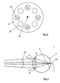
- a plurality of apertures 20 are introduced into the wheel 19, the centers lie on a circle in the center of which a central axis 21 of the wheel 19 is arranged.
- Each second of the apertures 20 contains an at least partially optically transparent element 22, which here in each case as a transparent cylinder 22, which preferably consists of PMMA (polymethyl acrylate), is trained.
- L n ⁇ ⁇ is the optical length L of a normal eye 2 of length ⁇ .
- this transparent cylinder 22 of length l is now introduced into the optical path or the light beam of the reference arm 17, then its optical arm length changes.
- the lengths l of the individual cylinders 22 are selected so that the arm length can be shortened in individual stages over all existing cylinders 22 in such a way that all commonly occurring lengths L of an eye 2 can be covered with the shortenings.
- the reference arm 17 of the interferometer 3 can therefore be shortened compared to the other arms of the interferometer 3 by the expected length L of the eye 2.
- the wheel 19 is driven by a stepper motor 23.
- the frequency of the drive circuit of a control / regulation 24 of the stepping motor 23 is selected so that the rotation is synchronized with a periodic linear movement 25 of the reflector 16. Therefore, the optical arm length of the reference arm 17 of the fiber optic interferometer 3 changes periodically between L 0 and L 0 + L , with the reference arm length L 0 without the cylinder 22 introduced.
- the light from the end of the fiber 14 is collected by another lens 26 and directed via a diffractive optical element (DOE) 27 and a beam splitter 28 to the eye 2 of the patient.
- the diffractive optical element 27 is designed so that the first diffraction order is focused on the surface 4 'of the cornea 4. To ensure that at least during the time of the actual measurement no distortions of the measurement occur, it must be ensured that the surface 4 'of the cornea 4 of the eye 2, which is measured at a defined constant distance from the system 1 or at least to the diffractive optical element 27 remains. This can, for example, via a corresponding Support for the chin and forehead of the patient, which is directly coupled to the system 1, as is known from devices for measuring the visual acuity and the like per se.
- the diffraction efficiency of the diffractive optical element 27 is chosen so that only about five percent of the incident light is diffracted into the first diffraction order.
- the visual system of the eye 2 consisting of the cornea 4 and the lens 5, concentrates the zeroth diffraction order of the diffractive optical element 27 in the background of the eye 2 on the retina 6 and generates by reflection a secondary light source 29 on the retina 6.
- the focused on the surface 4 'of the cornea 4 beam is partially reflected by this.
- the reflectance of the cornea 4 is about four percent.
- Another five percent of the reflected light from the cornea 4 is collected by the diffractive optical element 27 in a focus. They are thus lost for system 1, as only the portion of the light arriving in parallel with lens 26 is concentrated in the end of fiber 14.
- the intensity of this light flux of the reflected light from the cornea 4 collected by the lens 26 into the end of the fiber 14 is thus also only 10 -4 times the intensity of the input light. Therefore, it is in the reflected from the cornea 4 Light around a light of the same intensity as the light from the secondary light source 29 on the retina 6.
- the two light beams of comparable intensity are then focused by means of the converging lens 26 in the end of the fiber 14.
- the other part of the light incident on the beam splitter 28 penetrates it and passes via an optical imaging device 30 to the device 9 for detecting the aberrations in the wavefronts, which is designed here as a Hartmann-Shack sensor 9.
- the beam splitter 28 is thus achieved that the secondary light source 29 can be used on the retina 6 simultaneously for the measurement of the length L of the eye 2 and the measurement of the aberrations.
- the Hartmann-Shack sensor 9 has the imaging device 30 with two converging lenses 31 and 32, a diaphragm 33, a lens array 34 and a detector array 35, preferably of CCD sensors.
- the converging lens 31 focuses the light beams originating from the secondary light source 29 in the region of the diaphragm 33.
- the light reflected by the surface 4 'of the cornea 4 is divergent and is parallelized by the converging lens 31. These parallel rays of light reflected from the cornea 4 are then shaded by the aperture 33.
- the diaphragm 33 thus acts as a radiation barrier, which eliminates almost all light reflected by the cornea 4.
- the light of the secondary light source 29 on the retina 6 is focused in the region of the diaphragm 33 and can penetrate the diaphragm 33 unhindered in this way. It is then collected by the converging lens 32 into a parallel beam which impinges on the lens array 34.
- the optical imaging device 30 with the two converging lenses 31 and 32 and the diaphragm 33 thus forms the pupil 8 of the eye 2 on the plane of the lens array 34.
- Each one of the lenses 34a, 34, 34c, of which three exemplified here of the lens array 34, the light beams impinging on each of the lenses 34a, 34, 34c focus on the detector array 35 with the at least one CCD sensor.
- a certainly useful size of the lens array 34 is approximately 5 ⁇ 5 to 20 ⁇ 20 individual lenses 34a, 34b, 34c,....
- the focal points produced by the individual lenses 34a, 34b, 34c are equidistant and form a regular spot pattern.
- the spot pattern is correspondingly distorted.
- Fig. 3 it can be seen that the rays of the beam, from the pupil 8 of the eye. 2 emerges than the normals of a surface 36 can be considered.
- the surface 36 as a whole is a sphere when the rays have a common point of intersection.
- the surfaces 36 seen as a whole are an aspherical body. It is in principle so thought that the coupled via the interferometer 3 in the eye 2 light beam has a diameter so small that it penetrates through the center of the pupil 8 in the eye 2. This can be ensured that the beam during penetration no distortions or changes are experienced in the eye 2, since generally no aberrations occur in the proximal or paraxial areas of the cornea 4 and the lens 5. This is also particularly favorable, since any aberrations that may occur have no influence on the measurement of the length L of the eye 2 via the interferometer 3, which will be described in more detail below.
- the on the visual system again emerging from the eye 2 light rays reach among other things through the non-axis region of the pupil 8 in mydriasis; so that possibly occurring aberrations, which could adversely affect in particular the night-vision capability of the patient, can be detected via the Hartmann-Shack sensor 9.
- Fig. 3 this is indicated in principle by the fact that a greater deviation from the ideal surface in the form of a spherical segment is indicated on the surface 36 in the edge region, as is the case in the paraxial or near-axis regions.
- the function describing the surface 36 may be described by Zernike polynomials, which are functions in the polar coordinates ⁇ and ⁇ in the pupil plane 37 of FIG.
- the coordinate p is normalized and assumed to be 0 at the center of the pupil 8 and 1 at the pupil 8 edge.
- the so-called Seidel aberrations one needs eight Zernike polynomials to describe the aspherical surface: f ( ⁇ .
- ⁇ i 1 8th a i Z i ( ⁇ . ⁇ )
- Z 1 and Z 2 represent the inclination
- Z 3 defocusing
- Z 4 and Z 5 the astigmatism
- Z 6 and Z 7 the asymmetry error
- Z 8 the spherical aberration.
- any other wavefront analysis principle such as an interferometer test apparatus, may also be used for the system 1.
- any other wavefront analysis principle such as an interferometer test apparatus
- the radiation from the secondary light source 29 on the retina 6 of the eye 2 and the radiation reflected from the reflector 16 are superimposed by the 3dB coupler 12.
- the radiation passes through a fiber 39 to a detector 40, which is also formed in a particularly advantageous manner as a CCD sensor, and is registered by this.
- the moving reflector 16 leads to a temporary change in the length of the reference arm 17.
- the light source 10 is a superluminescent diode (SLD) with a coherence length in the order of 20 ⁇ m .
- a modulated signal is detected at the detector 40 when the length of the reference arm 17 within the coherence length of the light source 10 is equal to the length of a portion of the system 1 hereinafter referred to as the test arm 41.
- the test arm 41 thereby comprises the fiber 14, the lens 26, the diffractive optical element 27 and the beam splitter 28 and its length L to be measured eye. 2
- the retinal and corneal signals at the detector 40 are recorded with an analog-to-digital (AD) converter 42.
- AD analog-to-digital
- This data acquisition with detector 40 and AD converter, 42 is synchronized with a start signal sent from the controller 24 of the stepper motor 23 when the light beam in the reference arm 17 penetrates one of the PMMA cylinders 22 on the rotating wheel 19.
- the light beam in the reference arm 17 penetrates the PMMA cylinders 22 and the apertures 22 in a time interval T of the same duration, since the diameters of the PMMA cylinders 22 and the apertures 20 are equal.
- the reflector 16 of the reference arm 17 performs during this time interval T, in which the light beam of the reference arm 17 penetrates the PMMA cylinder 22, several times the periodic forward and backward movement 25 from.
- the signal coming from the detector 40 is switched via the AD converter 42 and a duplexer 43 to a RAM register 44 when the reflector 16 is in forward motion, while an address pointer of the RAM register 44 is counted up. On the other hand, if the reflector 16 moves backward, the address pointer of the RAM register 44 is counted down.
- u (t)
- f 2 ( t ) + ( H ⁇ f ( t ) ⁇ ) 2
- a possible bandwidth d of the movement 25 of the reflector 16 is chosen so that L ⁇ ⁇ / 2 the expected eye length distribution of the patient population, which is generally between 24mm and 28mm covering.
- the location of the center of the corneal Reflexes and the retinal reflex is calculated from data vectors, which were recorded during the time interval T , in a central all-calculating and controlling data processing unit 46.
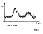
- the signal corresponding to the reflex from the retina 6 according to FIG. 6 consists of two reflections. The first, larger of these reflexes comes from the epithelial pigment, the so-called pars pigmentosa, which is located immediately behind the receptor layer of the retina 6.
- the second, smaller of the reflexes comes from the pars nervosa, a nerve layer that is located directly in front of the receptor layer of the retina 6.
- the average of the positions of the two tips can be used for the position of the retina 6, since the two layers pars pigmentosa and pars nervosa are arranged very close to each other and their average position corresponds practically to the position of the retina 6.
- the signal corresponding to the reflex from the cornea 4 consists of only one reflex from the surface 4 'of the cornea 4, the so-called epithelium anterius, so that The position of the cornea 4 can be used directly.
- the eye length L is then calculated from the difference between the two positions:
Landscapes
- Life Sciences & Earth Sciences (AREA)
- Health & Medical Sciences (AREA)
- Physics & Mathematics (AREA)
- Heart & Thoracic Surgery (AREA)
- Molecular Biology (AREA)
- Ophthalmology & Optometry (AREA)
- Engineering & Computer Science (AREA)
- Biomedical Technology (AREA)
- General Physics & Mathematics (AREA)
- Medical Informatics (AREA)
- Biophysics (AREA)
- Surgery (AREA)
- Animal Behavior & Ethology (AREA)
- General Health & Medical Sciences (AREA)
- Public Health (AREA)
- Veterinary Medicine (AREA)
- Eye Examination Apparatus (AREA)
- Length Measuring Devices By Optical Means (AREA)
Claims (21)
- Système de mesure sans contact de la qualité de reproduction optique d'un oeil (2) avec un interféromètre (3), dans lequel le système est aménagé de telle sorte qu'il réalise le procédé de mesure suivant : au moins une impulsion lumineuse est couplée dans l'oeil (2) avec une courte longueur de cohérence par une source de lumière (10), sachant que l'on fait varier la longueur de trajectoire optique d'au moins un bras de l'interféromètre (3) pour la mesure de la longueur (L) de l'oeil (2), jusqu'à ce qu'il se produise dans un détecteur (40) un motif d'interférence typique entre une réflexion de la cornée (4) et une réflexion de la rétine (6) de l'oeil (2), lequel, avec un tronçon de course (As) connu de la variation de la trajectoire optique, permet des conclusions sur la longueur (L) de l'oeil (2), sachant que la variation de la longueur de trajectoire optique s'effectue par l'introduction de premiers éléments (22) optiquement au moins partiellement transparents, et par au moins un deuxième élément (16) de l'interféromètre, pouvant être déplacé de façon définie dans l'au moins un bras (17) respectivement de l'interféromètre (3), et sachant que la longueur optique du premier élément (22) au moins partiellement transparent est adaptée à la longueur optique de l'oeil (2).
- Système selon la revendication 1,
caractérisé en ce que l'élément de l'interféromètre (3) pouvant être déplacé de façon définie est configuré comme réflecteur (16). - Système selon la revendication 2,
caractérisé en ce que le déplacement (25) du réflecteur (16) et l'introduction de l'élément (22) optiquement au moins partiellement transparent s'effectue dans le chemin des rayons du même bras (17) de l'interféromètre (3). - Système selon la revendication 1, 2 ou 3,
caractérisé en ce que l'interféromètre (3) est configuré comme interféromètre à fibres optiques. - Système selon l'une des revendications 1 à 4,
caractérisé en ce que la réflexion de la rétine (6) accède, en mydriase de l'oeil (2), par un dispositif d'imagerie optique (30) à un dispositif (9) pour la saisie de l'aberration des fronts d'ondes. - Système selon la revendication 5,
caractérisé en ce que le dispositif pour la saisie de l'aberration des fronts d'ondes en mydriase de l'oeil (2) est configuré comme capteur de Hartmann-Shack (9). - Système selon l'une des revendications 1 à 6,
caractérisé en ce que le réflecteur (16) est déplacé de façon mesurable dans sa position linéaire au moyen d'un dispositif d'entraînement (18). - Système selon l'une des revendications 1 à 7,
caractérisé en ce que les éléments optiquement au moins partiellement transparents sont configurés comme cylindres (22) en poly(méthacrylate de méthyle), c'est-à-dire en PMMA. - Système selon la revendication 8,
caractérisé en ce que les cylindres (22) sont montés sur une roue (19) disposée au moins à peu près perpendiculairement à l'axe optique du réflecteur. - Système selon la revendication 9,
caractérisé en ce que l'un respectivement des cylindres (22) sur la roue (19) peut être basculé au choix dans le trajet de la lumière à la manière d'un barillet de revolver. - Système selon la revendication 9 ou 10,
caractérisé en ce que la roue (19) est entraînée par un moteur pas à pas (23). - Système selon la revendication 9, 10 ou 11,
caractérisé en ce que des ouvertures de diaphragme (20) et des cylindres (22) sont disposés alternativement sur la roue (19). - Système selon l'une des revendications 1 à 12,
caractérisé en ce qu'une diode superélectroluminescente, c'est-à-dire une SLD, sert de source de lumière (10). - Système selon l'une des revendications 4 à 13,
caractérisé en ce que la lumière accède d'une extrémité d'une fibre (14) de l'interféromètre (3) dans l'oeil (2) via un dispositif d'imagerie optique. - Système selon la revendication 14,
caractérisé en ce que le dispositif d'imagerie optique comporte au moins une lentille (26). - Système selon la revendication 14 ou 15,
caractérisé en ce que le dispositif d'imagerie optique comporte au moins un élément optique diffracteur (27). - Système selon la revendication 14, 15 ou 16,
caractérisé en ce que le dispositif d'imagerie optique comporte au moins un diviseur de faisceau (28) pour le couplage du dispositif (9) de saisie des aberrations des fronts d'ondes. - Système selon la revendication 16,
caractérisé en ce que l'élément optique diffracteur (27) est configuré de telle sorte que le premier ordre de diffraction est focalisé sur la surface (4') de la cornée (4). - Système selon l'une des revendications 6 à 18,
caractérisé en ce que le capteur de Hartmann-Shack (9) comporte une matrice de lentilles (34) et un champ de détection (35). - Système selon la revendication 19,
caractérisé en ce que le champ de détection (35) est formé de capteurs CCD. - Système selon l'une des revendications 1 à 20,
caractérisé par au moins une unité électronique de traitement de données (46/24) pour la saisie et le dépouillement des données de mesure, ainsi que pour la commande/régulation de la course de déplacement du réflecteur (16).
Applications Claiming Priority (3)
| Application Number | Priority Date | Filing Date | Title |
|---|---|---|---|
| DE10042751 | 2000-08-31 | ||
| DE10042751A DE10042751A1 (de) | 2000-08-31 | 2000-08-31 | System zur berührungslosen Vermessung der optischen Abbildungsqualität eines Auges |
| PCT/EP2001/010070 WO2002017775A1 (fr) | 2000-08-31 | 2001-08-31 | Systeme de mesure sans contact de la qualite de reproduction optique d'un oeil |
Publications (2)
| Publication Number | Publication Date |
|---|---|
| EP1223848A1 EP1223848A1 (fr) | 2002-07-24 |
| EP1223848B1 true EP1223848B1 (fr) | 2006-09-13 |
Family
ID=7654408
Family Applications (1)
| Application Number | Title | Priority Date | Filing Date |
|---|---|---|---|
| EP01965240A Expired - Lifetime EP1223848B1 (fr) | 2000-08-31 | 2001-08-31 | Systeme de mesure sans contact de la qualite de reproduction optique d'un oeil |
Country Status (6)
| Country | Link |
|---|---|
| US (1) | US7084986B2 (fr) |
| EP (1) | EP1223848B1 (fr) |
| JP (1) | JP4782359B2 (fr) |
| AT (1) | ATE339153T1 (fr) |
| DE (2) | DE10042751A1 (fr) |
| WO (1) | WO2002017775A1 (fr) |
Families Citing this family (40)
| Publication number | Priority date | Publication date | Assignee | Title |
|---|---|---|---|---|
| CN100502762C (zh) * | 1998-12-10 | 2009-06-24 | 卡尔蔡斯耶拿有限公司 | 无接触式测量眼睛轴长和角膜曲率半径的组合仪器 |
| DE10142001A1 (de) * | 2001-08-28 | 2003-03-20 | Zeiss Carl Jena Gmbh | Optische Multiplex Kurzkohärenz-Interferometrie am Auge |
| FR2837373A1 (fr) * | 2002-03-20 | 2003-09-26 | Luneau Sa | Dispositif de mesure des proprietes optiques de l'oeil |
| US6736510B1 (en) * | 2003-02-04 | 2004-05-18 | Ware Tec Vision Systems, Inc. | Ophthalmic talbot-moire wavefront sensor |
| US7556378B1 (en) | 2003-04-10 | 2009-07-07 | Tsontcho Ianchulev | Intraoperative estimation of intraocular lens power |
| DE10342175A1 (de) * | 2003-09-12 | 2005-04-14 | Optocraft Gmbh | Vorrichtung und Verfahren zur Messung der Oberflächentopographie und Wellenaberrationen eines Linsensystems, insbesondere eines Auges |
| US20050117117A1 (en) * | 2003-12-02 | 2005-06-02 | Dan Bourla | Intraoperative biometry |
| FR2865538B1 (fr) * | 2004-01-22 | 2007-10-19 | Centre Nat Rech Scient | Dispositif et procede pour mesurer le contraste des franges dans un interferometre de michelson, et systeme d'examen de l'oeil incluant un tel dispositif |
| AT501056B1 (de) * | 2004-02-06 | 2007-04-15 | Zeiss Carl Meditec Ag | Kurzkohärenz-interferometrische längenmessung am auge |
| ES2665536T3 (es) | 2004-04-20 | 2018-04-26 | Alcon Research, Ltd. | Microscopio quirúrgico y sensor de frente de onda integrados |
| ATE449319T1 (de) * | 2004-08-11 | 2009-12-15 | Max Planck Gesellschaft | Verfahren und vorrichtung zur messung von wellenfronten |
| US7872760B2 (en) * | 2004-10-29 | 2011-01-18 | Degudent Gmbh | Method and device for detecting the contour data and/or optical characteristics of a three-dimensional semi-transparent object |
| WO2006078802A1 (fr) * | 2005-01-21 | 2006-07-27 | Massachusetts Institute Of Technology | Procedes et appareil pour le balayage de la tomographie de coherence optique |
| US7400410B2 (en) * | 2005-10-05 | 2008-07-15 | Carl Zeiss Meditec, Inc. | Optical coherence tomography for eye-length measurement |
| US8079707B2 (en) | 2006-10-25 | 2011-12-20 | Carl Zeiss Vision Gmbh | Eyeglass prescription method |
| EP2081484A1 (fr) * | 2006-11-16 | 2009-07-29 | Rsem, Limited Partnership | Appareil et procédé pour mesurer un déplacement dans un il in vivo in situ, et procédé d'évaluation |
| US7575322B2 (en) * | 2007-05-11 | 2009-08-18 | Amo Development Llc. | Auto-alignment and auto-focus system and method |
| EP2150169B1 (fr) | 2007-05-17 | 2016-04-06 | AMO Development, LLC | Systèmes d'ablation épithéliale au laser personnalisés |
| US8016420B2 (en) | 2007-05-17 | 2011-09-13 | Amo Development Llc. | System and method for illumination and fixation with ophthalmic diagnostic instruments |
| DE102007032001B4 (de) * | 2007-07-09 | 2009-02-19 | Carl Zeiss Vision Gmbh | Vorrichtung und Verfahren zur Bestimmung der erforderlichen Korrektur der Fehlsichtigkeit eines Auges |
| US8727532B2 (en) | 2007-07-24 | 2014-05-20 | Sis Ag, Surgical Instrument Systems | Ophthalmological measurement apparatus and measurement method |
| EP2359743B1 (fr) * | 2007-07-24 | 2012-12-05 | SIS AG, Surgical Instrument Systems | Dispositif de mesure ophtalmologique et procédé de mesure |
| DE102007046507A1 (de) * | 2007-09-28 | 2009-04-02 | Carl Zeiss Meditec Ag | Kurzkoheränz-Interferometer |
| US7594729B2 (en) | 2007-10-31 | 2009-09-29 | Wf Systems, Llc | Wavefront sensor |
| US9186059B2 (en) * | 2007-12-21 | 2015-11-17 | Bausch & Lomb Incorporated | Ophthalmic instrument alignment apparatus and method of using same |
| US20100030570A1 (en) | 2008-08-04 | 2010-02-04 | Carl Zeiss Vision Gmbh | Systems and methods for ordering lenses |
| WO2010017954A2 (fr) * | 2008-08-12 | 2010-02-18 | Carl Zeiss Meditec Ag | Réflectométrie optique cohérente à résolution en profondeur |
| US8550624B2 (en) | 2008-11-06 | 2013-10-08 | Wavetec Vision Systems, Inc. | Optical angular measurement system for ophthalmic applications and method for positioning of a toric intraocular lens with increased accuracy |
| US8294971B2 (en) * | 2008-12-18 | 2012-10-23 | Bausch • Lomb Incorporated | Apparatus comprising an optical path delay scanner |
| JP5232038B2 (ja) * | 2009-02-12 | 2013-07-10 | 株式会社ニデック | 眼寸法測定装置 |
| DE102009030466A1 (de) * | 2009-06-23 | 2011-01-05 | Carl Zeiss Meditec Ag | Verfahren und Vorrichtung zur Ausrichtung von ortsbezogenen Augendaten |
| US8876290B2 (en) | 2009-07-06 | 2014-11-04 | Wavetec Vision Systems, Inc. | Objective quality metric for ocular wavefront measurements |
| WO2011008609A1 (fr) | 2009-07-14 | 2011-01-20 | Wavetec Vision Systems, Inc. | Système de mesure pour chirurgie ophtalmique |
| ES2653970T3 (es) | 2009-07-14 | 2018-02-09 | Wavetec Vision Systems, Inc. | Determinación de la posición efectiva de la lente de una lente intraocular utilizando potencia refractiva afáquica |
| US9072462B2 (en) | 2012-09-27 | 2015-07-07 | Wavetec Vision Systems, Inc. | Geometric optical power measurement device |
| JP6097542B2 (ja) | 2012-12-10 | 2017-03-15 | キヤノン株式会社 | 補償光学装置、補償光学装置の制御方法、画像取得装置およびプログラム |
| US20180042771A1 (en) | 2016-08-10 | 2018-02-15 | Amo Development, Llc | Epithelial ablation systems and methods |
| DE102016116468A1 (de) * | 2016-09-02 | 2018-03-08 | Osram Opto Semiconductors Gmbh | Optoelektronische anordnung |
| EP4278957A3 (fr) | 2017-07-27 | 2024-01-24 | Align Technology, Inc. | Système et procédés de traitement d'un aligneur orthodontique au moyen d'une tomographie par cohérence optique |
| EP3928683A1 (fr) * | 2020-06-24 | 2021-12-29 | Carl Zeiss Vision International GmbH | Dispositif et procédé pour déterminer au moins une aberration oculaire |
Family Cites Families (23)
| Publication number | Priority date | Publication date | Assignee | Title |
|---|---|---|---|---|
| JPH024310A (ja) * | 1988-06-16 | 1990-01-09 | Kowa Co | 眼科診断方法および装置 |
| JP2763584B2 (ja) * | 1989-05-09 | 1998-06-11 | 株式会社トプコン | 生体眼の前後径距離測定装置 |
| JP3090705B2 (ja) * | 1991-04-22 | 2000-09-25 | 株式会社トプコン | 眼軸長測定装置 |
| EP0581871B2 (fr) * | 1991-04-29 | 2009-08-12 | Massachusetts Institute Of Technology | Appareil d'imagerie optique et de mesure |
| JPH05261067A (ja) * | 1992-03-19 | 1993-10-12 | Topcon Corp | 眼内長さ測定装置 |
| US5537162A (en) * | 1993-12-17 | 1996-07-16 | Carl Zeiss, Inc. | Method and apparatus for optical coherence tomographic fundus imaging without vignetting |
| WO1995033970A1 (fr) | 1994-06-02 | 1995-12-14 | Massachusetts Institute Of Technology | Came rotative pour systemes optiques |
| JP3427209B2 (ja) * | 1994-07-31 | 2003-07-14 | 株式会社トプコン | 眼科装置 |
| US5644642A (en) * | 1995-04-03 | 1997-07-01 | Carl Zeiss, Inc. | Gaze tracking using optical coherence tomography |
| WO1996035100A1 (fr) * | 1995-05-04 | 1996-11-07 | Meridian Ag | Dispositif pour la mesure d'epaisseur d'objets transparents |
| ATA107495A (de) * | 1995-06-23 | 1996-06-15 | Fercher Adolf Friedrich Dr | Kohärenz-biometrie und -tomographie mit dynamischem kohärentem fokus |
| JP3653582B2 (ja) * | 1996-07-21 | 2005-05-25 | 株式会社トプコン | 眼科装置 |
| JP3706940B2 (ja) * | 1997-05-09 | 2005-10-19 | 株式会社トプコン | 眼特性測定装置 |
| JPH10267610A (ja) * | 1997-03-26 | 1998-10-09 | Kowa Co | 光学測定装置 |
| US5975699A (en) | 1998-04-29 | 1999-11-02 | Carl Zeiss, Inc. | Method and apparatus for simultaneously measuring the length and refractive error of an eye |
| US6137585A (en) * | 1998-05-15 | 2000-10-24 | Laser Diagnostic Technologies, Inc. | Method and apparatus for recording three-dimensional distribution of light backscattering potential in transparent and semi-transparent structures |
| US6053613A (en) * | 1998-05-15 | 2000-04-25 | Carl Zeiss, Inc. | Optical coherence tomography with new interferometer |
| US6098887A (en) * | 1998-09-11 | 2000-08-08 | Robotic Vision Systems, Inc. | Optical focusing device and method |
| US6601956B1 (en) * | 1998-11-13 | 2003-08-05 | Benedikt Jean | Method and apparatus for the simultaneous determination of surface topometry and biometry of the eye |
| CN100502762C (zh) * | 1998-12-10 | 2009-06-24 | 卡尔蔡斯耶拿有限公司 | 无接触式测量眼睛轴长和角膜曲率半径的组合仪器 |
| US6191862B1 (en) | 1999-01-20 | 2001-02-20 | Lightlab Imaging, Llc | Methods and apparatus for high speed longitudinal scanning in imaging systems |
| ATE268901T1 (de) * | 1999-01-29 | 2004-06-15 | June Iris Medford | Optisches kohärenzmikroskop und verfahren zur schnellen 3d-in-vivo -visualisierung biologischer funktionen |
| US6002484A (en) * | 1999-06-18 | 1999-12-14 | Rozema; Jos J. | Phase contrast aberroscope |
-
2000
- 2000-08-31 DE DE10042751A patent/DE10042751A1/de not_active Withdrawn
-
2001
- 2001-08-31 AT AT01965240T patent/ATE339153T1/de not_active IP Right Cessation
- 2001-08-31 DE DE50111000T patent/DE50111000D1/de not_active Expired - Lifetime
- 2001-08-31 US US10/129,255 patent/US7084986B2/en not_active Expired - Fee Related
- 2001-08-31 WO PCT/EP2001/010070 patent/WO2002017775A1/fr active IP Right Grant
- 2001-08-31 JP JP2002522756A patent/JP4782359B2/ja not_active Expired - Fee Related
- 2001-08-31 EP EP01965240A patent/EP1223848B1/fr not_active Expired - Lifetime
Also Published As
| Publication number | Publication date |
|---|---|
| EP1223848A1 (fr) | 2002-07-24 |
| ATE339153T1 (de) | 2006-10-15 |
| US7084986B2 (en) | 2006-08-01 |
| DE50111000D1 (de) | 2006-10-26 |
| WO2002017775A1 (fr) | 2002-03-07 |
| DE10042751A1 (de) | 2002-03-14 |
| US20040061830A1 (en) | 2004-04-01 |
| JP2004507306A (ja) | 2004-03-11 |
| JP4782359B2 (ja) | 2011-09-28 |
Similar Documents
| Publication | Publication Date | Title |
|---|---|---|
| EP1223848B1 (fr) | Systeme de mesure sans contact de la qualite de reproduction optique d'un oeil | |
| DE60121123T2 (de) | Verfahren und vorrichtung zur messung von refraktiven fehlern eines auges | |
| DE102005031496B4 (de) | Vorrichtung zum Bestimmen der Wellenfront von Licht- und Operationsmikroskop mit Vorrichtung zum Bestimmen der Wellenfront von Licht | |
| DE69528024T2 (de) | Mit optischer Kohärenz-Tomographie gesteuerter chirurgischer Apparat | |
| DE69812834T2 (de) | Verfahren und Gerät zur Ermittlung von optischen Eigenschaften der Cornea | |
| EP1232377B1 (fr) | Procede et dispositif pour mesurer les proprietes optiques d'au moins deux secteurs distants l'un de l'autre dans un objet transparent et/ou diffusant | |
| DE60035643T2 (de) | Verfahren und Vorrichtung zur Messung von Refraktionseigenschaften des menschlichen Auges | |
| DE69902549T2 (de) | Gerät und verfahren zur messung von fehlsichtigkeiten eines menschlichen auges | |
| EP2134247B1 (fr) | Procédé de mesure de la longueur d'un axe à fonction de mesure élargie dans la partie avant de l'oeil | |
| DE19950792A1 (de) | Wellenfrontsensor mit Mehrleistungsstrahlmodi und unabhängiger Abgleichkamera | |
| WO2010031540A2 (fr) | Système de mesure utilisé en chirurgie ophtalmologique | |
| DE60125319T2 (de) | Wellenfrontrefraktor zur gleichzeitigen aufnahme zweier hartmann-shack-bilder | |
| WO2012160049A1 (fr) | Système destiné à déterminer la topographie de la cornée d'un œil | |
| WO2005045362A1 (fr) | Appareil de mesure interferometrique de la longueur d'un oeil ayant une sensibilite accrue | |
| EP1662981B1 (fr) | Dispositif et procede pour mesurer la topographie superficielle et l'aberration d'onde d'un systeme a lentille, notamment d'un oeil | |
| DE10122248A1 (de) | Apparatur zur Messung der Augencharakteristik | |
| EP2542140A1 (fr) | Dispositif de diagnostic pour la détection d'une limite de couche dans un oeil, et élément annulaire pour le dispositif de diagnostic | |
| WO2012084170A9 (fr) | Dispositif de mesure par interférométrie de la longueur de l'œil et de la partie antérieure de l'œil | |
| DE102013021974B3 (de) | Vorrichtung zur Bestimmung einer Ametropie eines Auges | |
| EP3585245B1 (fr) | Procédé et dispositif pour la topographie à haute résolution de la cornée d'un oeil | |
| DE10196985T5 (de) | System und Verfahren zur Bestimmung der Doppelbrechung des Anteriorsegments eines Patientenauges | |
| DE60204178T2 (de) | Aberrationsfreie Abbildung des Augenhintergrundes | |
| EP0563454A1 (fr) | Procédé et dispositif pour examiner les yeux | |
| EP1624795B1 (fr) | Procede et dispositif permettant de mesurer la section oculaire anterieure | |
| EP3517021A1 (fr) | Procédé et système à champ plein oct permettant de générer une image du fond de l' il |
Legal Events
| Date | Code | Title | Description |
|---|---|---|---|
| PUAI | Public reference made under article 153(3) epc to a published international application that has entered the european phase |
Free format text: ORIGINAL CODE: 0009012 |
|
| 17P | Request for examination filed |
Effective date: 20020419 |
|
| AK | Designated contracting states |
Kind code of ref document: A1 Designated state(s): AT BE CH CY DE DK ES FI FR GB GR IE IT LI LU MC NL PT SE TR |
|
| 17Q | First examination report despatched |
Effective date: 20050331 |
|
| GRAP | Despatch of communication of intention to grant a patent |
Free format text: ORIGINAL CODE: EPIDOSNIGR1 |
|
| GRAS | Grant fee paid |
Free format text: ORIGINAL CODE: EPIDOSNIGR3 |
|
| GRAA | (expected) grant |
Free format text: ORIGINAL CODE: 0009210 |
|
| AK | Designated contracting states |
Kind code of ref document: B1 Designated state(s): AT BE CH CY DE DK ES FI FR GB GR IE IT LI LU MC NL PT SE TR |
|
| PG25 | Lapsed in a contracting state [announced via postgrant information from national office to epo] |
Ref country code: IT Free format text: LAPSE BECAUSE OF FAILURE TO SUBMIT A TRANSLATION OF THE DESCRIPTION OR TO PAY THE FEE WITHIN THE PRESCRIBED TIME-LIMIT;WARNING: LAPSES OF ITALIAN PATENTS WITH EFFECTIVE DATE BEFORE 2007 MAY HAVE OCCURRED AT ANY TIME BEFORE 2007. THE CORRECT EFFECTIVE DATE MAY BE DIFFERENT FROM THE ONE RECORDED. Effective date: 20060913 Ref country code: IE Free format text: LAPSE BECAUSE OF FAILURE TO SUBMIT A TRANSLATION OF THE DESCRIPTION OR TO PAY THE FEE WITHIN THE PRESCRIBED TIME-LIMIT Effective date: 20060913 Ref country code: FI Free format text: LAPSE BECAUSE OF FAILURE TO SUBMIT A TRANSLATION OF THE DESCRIPTION OR TO PAY THE FEE WITHIN THE PRESCRIBED TIME-LIMIT Effective date: 20060913 Ref country code: NL Free format text: LAPSE BECAUSE OF FAILURE TO SUBMIT A TRANSLATION OF THE DESCRIPTION OR TO PAY THE FEE WITHIN THE PRESCRIBED TIME-LIMIT Effective date: 20060913 |
|
| REG | Reference to a national code |
Ref country code: GB Ref legal event code: FG4D Free format text: NOT ENGLISH |
|
| REG | Reference to a national code |
Ref country code: CH Ref legal event code: EP |
|
| REG | Reference to a national code |
Ref country code: IE Ref legal event code: FG4D Free format text: LANGUAGE OF EP DOCUMENT: GERMAN |
|
| REF | Corresponds to: |
Ref document number: 50111000 Country of ref document: DE Date of ref document: 20061026 Kind code of ref document: P |
|
| PG25 | Lapsed in a contracting state [announced via postgrant information from national office to epo] |
Ref country code: DK Free format text: LAPSE BECAUSE OF FAILURE TO SUBMIT A TRANSLATION OF THE DESCRIPTION OR TO PAY THE FEE WITHIN THE PRESCRIBED TIME-LIMIT Effective date: 20061213 Ref country code: SE Free format text: LAPSE BECAUSE OF FAILURE TO SUBMIT A TRANSLATION OF THE DESCRIPTION OR TO PAY THE FEE WITHIN THE PRESCRIBED TIME-LIMIT Effective date: 20061213 |
|
| PG25 | Lapsed in a contracting state [announced via postgrant information from national office to epo] |
Ref country code: ES Free format text: LAPSE BECAUSE OF FAILURE TO SUBMIT A TRANSLATION OF THE DESCRIPTION OR TO PAY THE FEE WITHIN THE PRESCRIBED TIME-LIMIT Effective date: 20061224 |
|
| PG25 | Lapsed in a contracting state [announced via postgrant information from national office to epo] |
Ref country code: PT Free format text: LAPSE BECAUSE OF FAILURE TO SUBMIT A TRANSLATION OF THE DESCRIPTION OR TO PAY THE FEE WITHIN THE PRESCRIBED TIME-LIMIT Effective date: 20070226 |
|
| NLV1 | Nl: lapsed or annulled due to failure to fulfill the requirements of art. 29p and 29m of the patents act | ||
| ET | Fr: translation filed | ||
| REG | Reference to a national code |
Ref country code: IE Ref legal event code: FD4D |
|
| PLBE | No opposition filed within time limit |
Free format text: ORIGINAL CODE: 0009261 |
|
| STAA | Information on the status of an ep patent application or granted ep patent |
Free format text: STATUS: NO OPPOSITION FILED WITHIN TIME LIMIT |
|
| 26N | No opposition filed |
Effective date: 20070614 |
|
| BERE | Be: lapsed |
Owner name: CARL ZEISS JENA G.M.B.H. Effective date: 20070831 |
|
| PG25 | Lapsed in a contracting state [announced via postgrant information from national office to epo] |
Ref country code: MC Free format text: LAPSE BECAUSE OF NON-PAYMENT OF DUE FEES Effective date: 20070831 Ref country code: GR Free format text: LAPSE BECAUSE OF FAILURE TO SUBMIT A TRANSLATION OF THE DESCRIPTION OR TO PAY THE FEE WITHIN THE PRESCRIBED TIME-LIMIT Effective date: 20061214 |
|
| REG | Reference to a national code |
Ref country code: GB Ref legal event code: 732E |
|
| PG25 | Lapsed in a contracting state [announced via postgrant information from national office to epo] |
Ref country code: BE Free format text: LAPSE BECAUSE OF NON-PAYMENT OF DUE FEES Effective date: 20070831 |
|
| REG | Reference to a national code |
Ref country code: FR Ref legal event code: TP |
|
| PG25 | Lapsed in a contracting state [announced via postgrant information from national office to epo] |
Ref country code: AT Free format text: LAPSE BECAUSE OF NON-PAYMENT OF DUE FEES Effective date: 20070831 |
|
| PG25 | Lapsed in a contracting state [announced via postgrant information from national office to epo] |
Ref country code: LU Free format text: LAPSE BECAUSE OF NON-PAYMENT OF DUE FEES Effective date: 20070831 Ref country code: CY Free format text: LAPSE BECAUSE OF FAILURE TO SUBMIT A TRANSLATION OF THE DESCRIPTION OR TO PAY THE FEE WITHIN THE PRESCRIBED TIME-LIMIT Effective date: 20060913 |
|
| PG25 | Lapsed in a contracting state [announced via postgrant information from national office to epo] |
Ref country code: TR Free format text: LAPSE BECAUSE OF FAILURE TO SUBMIT A TRANSLATION OF THE DESCRIPTION OR TO PAY THE FEE WITHIN THE PRESCRIBED TIME-LIMIT Effective date: 20060913 |
|
| REG | Reference to a national code |
Ref country code: CH Ref legal event code: PFA Owner name: CARL ZEISS MEDITEC AG Free format text: CARL ZEISS MEDITEC AG#GOESCHWITZER STRASSE 51-52#07745 JENA (DE) -TRANSFER TO- CARL ZEISS MEDITEC AG#GOESCHWITZER STRASSE 51-52#07745 JENA (DE) |
|
| PGFP | Annual fee paid to national office [announced via postgrant information from national office to epo] |
Ref country code: GB Payment date: 20120821 Year of fee payment: 12 |
|
| PGFP | Annual fee paid to national office [announced via postgrant information from national office to epo] |
Ref country code: FR Payment date: 20120906 Year of fee payment: 12 |
|
| PGFP | Annual fee paid to national office [announced via postgrant information from national office to epo] |
Ref country code: DE Payment date: 20130821 Year of fee payment: 13 Ref country code: CH Payment date: 20130821 Year of fee payment: 13 |
|
| GBPC | Gb: european patent ceased through non-payment of renewal fee |
Effective date: 20130831 |
|
| REG | Reference to a national code |
Ref country code: FR Ref legal event code: ST Effective date: 20140430 |
|
| PG25 | Lapsed in a contracting state [announced via postgrant information from national office to epo] |
Ref country code: GB Free format text: LAPSE BECAUSE OF NON-PAYMENT OF DUE FEES Effective date: 20130831 |
|
| PG25 | Lapsed in a contracting state [announced via postgrant information from national office to epo] |
Ref country code: FR Free format text: LAPSE BECAUSE OF NON-PAYMENT OF DUE FEES Effective date: 20130902 |
|
| REG | Reference to a national code |
Ref country code: DE Ref legal event code: R119 Ref document number: 50111000 Country of ref document: DE |
|
| REG | Reference to a national code |
Ref country code: CH Ref legal event code: PL |
|
| PG25 | Lapsed in a contracting state [announced via postgrant information from national office to epo] |
Ref country code: LI Free format text: LAPSE BECAUSE OF NON-PAYMENT OF DUE FEES Effective date: 20140831 Ref country code: CH Free format text: LAPSE BECAUSE OF NON-PAYMENT OF DUE FEES Effective date: 20140831 |
|
| REG | Reference to a national code |
Ref country code: DE Ref legal event code: R119 Ref document number: 50111000 Country of ref document: DE Effective date: 20150303 |
|
| PG25 | Lapsed in a contracting state [announced via postgrant information from national office to epo] |
Ref country code: DE Free format text: LAPSE BECAUSE OF NON-PAYMENT OF DUE FEES Effective date: 20150303 |