EP1223456B1 - Strahlteiler zur Reduktion von polarisationsabhängigen Effekten - Google Patents
Strahlteiler zur Reduktion von polarisationsabhängigen Effekten Download PDFInfo
- Publication number
- EP1223456B1 EP1223456B1 EP01129780A EP01129780A EP1223456B1 EP 1223456 B1 EP1223456 B1 EP 1223456B1 EP 01129780 A EP01129780 A EP 01129780A EP 01129780 A EP01129780 A EP 01129780A EP 1223456 B1 EP1223456 B1 EP 1223456B1
- Authority
- EP
- European Patent Office
- Prior art keywords
- splitting device
- incident beam
- reflected
- beam splitter
- incident
- Prior art date
- Legal status (The legal status is an assumption and is not a legal conclusion. Google has not performed a legal analysis and makes no representation as to the accuracy of the status listed.)
- Expired - Lifetime
Links
Images

Classifications
-
- G—PHYSICS
- G02—OPTICS
- G02B—OPTICAL ELEMENTS, SYSTEMS OR APPARATUS
- G02B6/00—Light guides; Structural details of arrangements comprising light guides and other optical elements, e.g. couplings
- G02B6/24—Coupling light guides
- G02B6/26—Optical coupling means
- G02B6/28—Optical coupling means having data bus means, i.e. plural waveguides interconnected and providing an inherently bidirectional system by mixing and splitting signals
- G02B6/2804—Optical coupling means having data bus means, i.e. plural waveguides interconnected and providing an inherently bidirectional system by mixing and splitting signals forming multipart couplers without wavelength selective elements, e.g. "T" couplers, star couplers
- G02B6/2848—Optical coupling means having data bus means, i.e. plural waveguides interconnected and providing an inherently bidirectional system by mixing and splitting signals forming multipart couplers without wavelength selective elements, e.g. "T" couplers, star couplers having refractive means, e.g. imaging elements between light guides as splitting, branching and/or combining devices, e.g. lenses, holograms
-
- G—PHYSICS
- G02—OPTICS
- G02B—OPTICAL ELEMENTS, SYSTEMS OR APPARATUS
- G02B27/00—Optical systems or apparatus not provided for by any of the groups G02B1/00 - G02B26/00, G02B30/00
- G02B27/10—Beam splitting or combining systems
- G02B27/14—Beam splitting or combining systems operating by reflection only
- G02B27/144—Beam splitting or combining systems operating by reflection only using partially transparent surfaces without spectral selectivity
Definitions
- the present invention relates to optical beam splitters as devices for splitting up an incident optical beam into a plurality of sub-beams.
- a typical beam splitter comprises e.g. an etalon tilted 45° with respect to the incident beam. One portion of the incident beam will be reflected and another portion transmits through the beam splitter. The coupling ratio depends on the reflection/transmission properties of the etalon.
- Such fiber optic beam splitters also called couplers, are generally made up of fused fibers where two or more fibers with at least partially removed claddings are melt together.
- US-A-4,492,439 discloses a polarization independent beam splitter provided by a thin plate of birefringent material having a thickness chosen to interchange the characteristic polarization of the beam between the faces of the plate. The refection/refraction ratio at the two boundaries are then complementary and the combined effect is insensitive to the polarization of the incident beam in the Brewster angle.
- a beam splitter comprises a splitting device receiving an incident beam in an angle ⁇ with respect to the normal to the splitting device surface receiving the incident beam (for the sake of simplicity referred to as the 'optical axis').
- the angle ⁇ is to be selected that reflection at the splitting device is substantially independent of the polarization of the incident beam.
- the angle ⁇ is to be selected in a range, wherein the reflectivity of the splitting device is substantially the same for parallel (i.e. parallel to the plane built by the vector of propagation an the optical axis) and perpendicular (i.e. perpendicular to the plane built by the vector of propagation and the optical axis) polarization of the light.
- the angle ⁇ is preferably selected to be smaller than 1° to obtain a polarization dependent loss (PDL) smaller than 8 mdB.
- PDL shall mean here the ratio between maximum and minimum reflection or transmission for any state of polarization even though there are no losses connected with this difference.
- the splitting device reflects a portion of the incident beam at the same angle ⁇ to the optical axis, however, on opposite side with respect to the incident beam.
- the ratio of the intensities of the reflected beam with respect to the incident beam depends on the angle ⁇ , on the index of refraction of the splitting device and eventually on a coating (if provided) of the splitting device.
- the coupling ratio of the reflected beam will be substantially independent of the state of polarization of the incident beam.
- PDL can be reduced to a minimum.
- the splitting device is further designed to provide a second beam transmitting through the splitting device.
- the splitting device is preferably designed that the transmitted beam leaves the splitting device parallel to the optical axis.
- the transmitted beam leaves the splitting device surface on opposite side with respect entry side of the incident beam, thus having substantially the same propagation direction as the incident beam.
- small angular displacements with respect to the propagation direction of the incident beam might be advantageous e.g. when avoiding interference effects as explained later.
- the intensity of the transmitted beam with respect to the intensity of the incident beam will be substantially independent of the state of polarization of the incident beam due to the selection criterion of the angle ⁇ . In case losses can be neglected, the intensities of the reflected and the transmitted beam will sum up to the intensity of the incident beam.
- the invention provides a beam splitter having a splitting or coupling ratio that is substantially independent of the state of polarization of the incident beam, so that PDL can be minimized. It has been shown that beam splitters with PDL smaller than 10mdB can be easily achieved.
- the splitting device is provided to be wedge-shaped in order to avoid interference effects in the transmitted (output) beam.
- other shapes such as etalons, prisms or even lenses can be applied accordingly.
- the splitting device may be provided to be anti-reflective coated on one side.
- a collimating device e.g. a lens or a concave mirror
- the incident side i.e. the side of the splitting device receiving the incident beam
- the reflected beam will pass the collimating device.
- a first optical fiber for emitting the incident beam and a second optical fiber for receiving the reflected beam are provided in close proximity to each other.
- the first and second fibers are attached to each other using a capillary with an inner diameter of at least twice the diameter of the fibers or a double V-groove where the fibers are attached e.g. using glue.
- the incident beam from the first fiber is collimated by the collimating device and sent to the splitting device under the angle ⁇ .
- the reflected beam will be focused accordingly by the collimating device into the second fiber.
- the splitting device can be provided on its incident side with a coating material in order to influence the coupling ratio. Accordingly or alternatively, the material of the splitting device can be selected in order to influence the coupling ratio. In one embodiment, the properties of the splitting device can be modified in order to vary the splitting ratio. This can be accomplished e.g. by moving the splitting device with a variable thickness metallic coating perpendicular to the optical axis along the thickness gradient.
- PDL can be minimized also over a wide wavelength range; e.g. the wavelength dependency of an air glass transition is small due to the low dispersion of normal glasses. If coatings are to be used a special process has to be developed to yield low PDL for that coating.
- a compensator is provided within the reflected beam and due to the small separation of incident and reflected beam usually as well in the incident beam in order to balance remaining differences in transmission for different states of polarization of the reflected beam.
- An other preferred embodiment of such an compensator would be another etalon or wedge that can be rotated and tilted with respect to the beam to introduce additional polarization dependent transmission that compensates the effect of the polarization dependent reflection.
- a second collimating device can be provided between the splitting device and the third fiber.
- Another embodiment reflects the transmitted beam back through the first collimating element into a third fiber in the vicinity of the first two fibers.
- angled fiber ends can be used. These angled fiber end give rise to additional polarization depended transmission. Further improvements of the polarization dependency when coupling out of or back into a fiber can be achieved e.g. by applying an anti reflection coating on the fibers. Accordingly or alternatively it is possible to rotate the angled fibers odd multiplies of 90° around the optical axis with respect to each other. Since angled fibers when aligned with the optical axis pass the beam through the collimating device outside the center and therefore can rise to polarization dependent transmission, it is a further improvement to rotate the fibers in such a way that the beam will pass the collimating device in the center. Additionally the collimating device can be designed with a smaller numerical aperture, which leads to an improved performance over wavelength.
- the inventive beam splitter will be applied from both sides of the splitting device, so that the beam splitter receives incident beams at opposite sides of the splitting device.
- the incident beam of the above explanations shall be referred to as 'the first incident beam', while an incident beam received at another (preferably opposite) side of the splitting device shall be referred to as 'the second incident beam'.
- the second incident beam is directed to the splitting device with opposite propagation direction than the reflected beam, it will be split up by the splitting device just in accordance with the above said, however with opposite propagation directions.
- One portion of the second incident beam will be transmitted through the splitting device towards the source of the first incident beam (as provided from the other side of the splitting device).
- the other portion of the second incident beam will be reflected and travel back with substantially the same angular displacement as the second incident beam but on opposite side with respect to the optical axis.
- Such device might also be used as a four-port coupler.
- a four port coupler can also be built by combining two independent splitting devices as described above or by using both faces of the splitting device in contrast to the first embodiment where only one surface is used to reflect the beams travelling in opposite directions.
- the splitting device might be provided with two reflective surfaces, so that the first incident beam will be reflected partially into the first reflected portion by one of the reflective surfaces, whereas the second incident beam will be reflected partially into the second reflected portion by the other one of the reflective surfaces.
- a second splitting device can be provided and each of the two splitting devices bears one reflective surface. In that case, the first incident beam will be reflected partially into the first reflected portion by the reflective surface of the (first) splitting device, whereas the second incident beam will be reflected partially into the second reflected portion by the reflective surface of the second splitting device.
- each splitting device can be provided with a variable reflection coating and/or can be made of a material with variable index of refraction.
- the variation of reflection or the variation of the index of refraction of each splitting device can be provided along an axis substantially perpendicular to the optical axis. Each splitting device may also be moved along this axis.
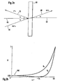
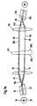
- Figure 1 shows a first embodiment of a beam splitter according to the present invention.
- Figures 2A and 2B illustrate the principle for designing the inventive beam splitter.
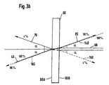
- Figures 3 illustrate further embodiments of the inventive beam splitter operated from opposite sides.
- two optical fibers 10 and 20 are provided in a ferrule 30.
- the first fiber 10 emits a first beam 40 collimated by a lens 50 and directed towards a splitting device 60.
- the beam 40 is directed in an angle ⁇ with respect to a normal 65 of the incident side of the splitting device 60.
- the splitting device 60 splits up the incident beam 40 into a reflected beam 70 and a transmitted beam 80.
- the reflected beam 70 travels also with the angle ⁇ to the normal 65 but with opposite propagation direction and on opposite side of the normal 65 than the incident beam 40.
- the transmitted beam 80 leaves the splitting device 60 also with the angle ⁇ to a normal 68 (of a side of the splitting device 60 where the transmitted beam 80 leaves the splitting device 60) and with the same propagation direction than the incident beam 40 (plus a lateral displacement between the normals 65 and 68).
- the example of Fig. 2A illustrates a splitting rate of 4% for the reflected beam 70 and 96% for the transmitted beam 80 (neglecting potential losses).
- the beam 70 reflected at the splitting device 60 will be focused by the lens 50 into the second fiber 20.
- the transmitted beam 80 will also be focused by a lens 110 into a third fiber 120.
- Figure 2B illustrates the principle to design the angle ⁇ .
- the reflectivity R at the splitting device 60 is shown for parallel (p) and perpendicular (s) polarized light and their dependencies from the angle ⁇ of the incident beam 40.
- the reflectivity of parallel (Rp) and perpendicular (Rs) polarized light is substantially equal.
- the area 100 is for relatively small angles ⁇ (here: smaller than about 5°), and the differences between parallel and perpendicular polarized light increase with increasing angle ⁇ .
- the angle ⁇ in the range 100 the reflection becomes substantially independent of the state of polarization of the incident beam 40.
- PDL values smaller than 8 mdB can be obtained.
- a compensator 75 can be provided within the reflected beam 70 in order to balance remaining differences in the state of polarization of the reflected beam. This can be achieved by placing an etalon or wedge in the beam that can be rotated around the optical axis and tilted perpendicular to it. The polarization dependent transmission through the first and - if there is no anti reflection coating applied - through the second air glass interface can be used to compensate for any remaining polarization dependency of the reflection.
- a second compensator 76 has to be placed after the splitting device 60 if the output port should be compensated as well.
- the splitting device 60 is preferably provided to be wedge-shaped. Additionally, the wedge can be chosen such that the transmitted beam is parallel to the optical axis.
- the second optical surface is preferably be anti-reflection coated to avoid losses together with a polarization dependency and additional unwanted reflections.
- the fibers 10, 20, 120 and 130 could be chosen to be single mode fibers.
- the fibers 20 and 130 can be chosen to be multimode.
- the fiber ends of the fibers 10 and 20 are provided angled in order to avoid back reflections of the fiber ends. Further the fibers 10 and 20 might be provided tilted with respect to the normal of the splitting device 60 in this case in order to pass the beam through the center of the collimating device.
- a fourth fiber 130 is provided close to the third fiber 120. The arrangement of the fibers 120 and 130 can be in accordance with the above said for fibers 10 and 20. The directions and angles of the beams are illustrated in Figure 3B.
- a beam 140 (broken line in Fig. 3A) emitted from the fiber 120 will be collimated by the lens 110 and directed towards the splitting device 60 in the angle ⁇ (to the normal 68 - see Fig. 3B).
- one portion 150 will be reflected back towards the lens 110 and the other portion 160 (broken line in Fig. 3B) will be transmitted through the splitting device 60 and focused by the lens 50 into the fiber 10.
- the beam 150 reflected back towards the lens 110 will be focused into the fiber 130.
- the beam splitter 60 might be provided with two reflective surfaces 60A and 60B, so that the first incident beam 40 will be reflected partially into the first reflected portion 70 by the reflective surface 60A, whereas the second incident beam 140 will be reflected partially into the second reflected portion 150 by the reflective surface 60B.
- the two reflective surfaces 60A and 60B might also be provided on two individual splitting devices (not shown in the Figures) each bearing one reflective surface. In that case, the first incident beam 40 will be reflected partially into the first reflected portion by the reflective surface of the (first) beam splitter 60, whereas the second incident beam 140 will be reflected partially into the second reflected portion by the reflective surface of the second beam splitter.
Landscapes
- Physics & Mathematics (AREA)
- General Physics & Mathematics (AREA)
- Optics & Photonics (AREA)
- Spectroscopy & Molecular Physics (AREA)
- Optical Couplings Of Light Guides (AREA)
- Optical Elements Other Than Lenses (AREA)
- Polarising Elements (AREA)
Claims (13)
- Ein Strahlteiler mit:wobei der Winkel α ausgewählt wird in einem Bereich, in dem die Reflektivität der Teilungsvorrichtung (60) im Wesentlichen diesselbe ist für parallele und senkrechte - relativ zu der Ebene, welche durch den Ausbreitungsvektor und die optische Achse der Teilungsvorrichtung (60) gebildet wird - Polarisation des ersten Einfallstrahls (40), so dass der reflektierte erste Teil (70) im Wesentlichen unabhängig ist von dem Polarisationsstatus des ersten Einfallstrahls (40).einer ersten optischen Faser (10) zum Emittieren eines ersten Einfallstrahis (40),einer Teilungsvorrichtung (60), angepasst zum Empfangen des ersten Einfallstrahls (40) auf einer ersten Oberfläche (60A) unter einem Winkel α in Bezug auf die optische Achse dieser Teilungsvorrichtung (60), zum Reflektieren eines ersten Teils (70) des ersten Einfallstrahls (40) an der ersten Oberfläche (60A) im Winkel α in Bezug auf die optische Achse dieser Teilungsvorrichtung (60) und auf der gegenüberliegenden Seite mit Hinblick auf den ersten Einfallstrahl (40), und zum Transmittieren eines zweiten Strahls (80) durch die Teilungsvorrichtung (60),eine zweite optische Faser (20) oder eine Detektionsvorrichtung, jede angepasst zum Empfangen des reflektierten ersten Teils (70), wobei die erste optische Faser (10) und die zweite optische Faser (20) oder die Detektionsvorrichtung nahe beieinander vorgesehen sind,eine Kollimationsvorrichtung (50), vorgesehen an der Einfallseite der Teilungsvorrichtung (60), so dass der erste Einfallstrahl (40) ausgerichtet wird und gelenkt in Richtung der Teilungsvorrichtung (60) und der reflektierte erste Teil (70) fokussiert wird in die zweite optische Faser (20) oder die Detektionsvorrichtung,
- Der Strahlteiler nach Anspruch 1, wobei das Verhältnis der Intensitäten des reflektierten ersten Teils (70) in Bezug auf den ersten Einfallstrahl (40) kontrolliert wird durch Kontrolle von einem aus: Winkel α, dem Brechungsindex der Teilungsvorrichtung (60), oder einer Beschichtung der Teilungsvorrichtung (60).
- Der Strahlteiler nach Anspruch 1 oder 2, wobei der zweite Strahl (80) die Teilungsvorrichtung (60) parallel zu der optischen Achse der Teilungsvorrichtung (60) verlässt, vorzugsweise auf der gegenüberliegenden Seite in Bezug auf die Einfallseite des ersten Einfallstrahls (40).
- Der Strahlteiler nach Anspruch 1 oder einem der oben genannten Ansprüche, wobei die Teilungsvorrichtung (60) vorgesehen ist aus Glas, und der Winkel α ausgewählt ist, kleiner als 5° zu sein.
- Der Strahlteiler nach Anspruch 1 oder einem der oben genannten Ansprüche, wobei die Teilungsvorrichtung (60) vorgesehen ist, auf einer Seite antireflektiv beschichtet zu sein und/oder keilförmig, um Interferenz-Effekte in dem zweiten Strahl (80) zu vermeiden.
- Der Strahlteiler nach Anspruch 1, wobei die erste optische Faser (10) und die zweite optische Faser (20) oder die Detektionsvorrichtung aneinander angeschlossen sind.
- Der Strahlteiler nach Anspruch 1 oder einem der oben genannten Ansprüche mit zusätzlich mindestens einem Kompensator (75,76) in mindestens einem der Strahlen (40,70,80) zum Ausgleichen der verbleibenden Differenzen im Polarisationsstatus.
- Der Strahlteiler nach Anspruch 1 oder einem der oben genannten Ansprüche, wobei die Teilungsvorrichtung (60) zusätzlich einen zweiten Einfallstrahl (140) empfängt in dem Winkel α in Bezug auf die optische Achse, aber auf der gegenüberliegenden Seite in Bezug auf den ersten Einfallstrahl (40).
- Der Strahlteiler nach Anspruch 8, wobei der zweite Einfallstrahl (140) ausgerichtet wird mit entgegengesetzter Ausbreitungsrichtung als der zweite Strahl (80), so dass ein zweiter Teil (160) des zweiten Einfallstrahls (140), der durch die Teilungsvorrichtung (60) übermittelt wird, die Teilungsvorrichtung (60) mit entgegengesetzter Richtung als der erste Einfallstrahl (40) verlassen wird.
- Der Strahlteiler nach Anspruch 8 oder 9 mit zusätzlich einer dritten optischen Faser (120) zum Empfangen des zweiten Strahls (80) und/oder Emittieren des zweiten Einfallstrahls (40), und/oder einer vierten optischen Faser (130) zum Empfangen des zweiten reflektierten Teils (150) des zweiten Einfallstrahls (40).
- Der Strahlteiler nach einem der Ansprüche 8 bis 10, wobei der erste Einfallstrahl (40) teilweise reflektiert wird in dem ersten reflektierten Teil (70) durch die erste Oberfläche der Teilungsvorrichtung (60), während der zweite Einfallstrahl (140) teilweise reflektiert wird in dem zweiten reflektierten Teil (150) durch entweder eine zweite Oberfläche der Teilungsvorrichtung (60) oder durch eine erste Oberfläche einer zweiten Teilungsvorrichtung.
- Der Strahlteiler nach Anspruch 1 oder einem der oben genannten Ansprüche, wobei zum Anpassen des Verhältnisses der reflektierten und übertragenen Energie zumindest die Teilungsvorrichtung (60) oder die zweite Teilungsvorrichtung versehen ist mit einer variablen Reflektionsbeschichtung und/oder aus Material besteht mit variablem Brechungsindex.
- Der Strahlteiler nach Anspruch 12, wobei die Reflektionsvariation oder die Variation des Brechungsindex vorgesehen ist entlang einer Achse, die im Wesentlichen senkrecht ist zu der optischen Achse und/oder die Teilungsvorrichtung (60) entlang dieser Achse bewegt werden kann.
Priority Applications (4)
| Application Number | Priority Date | Filing Date | Title |
|---|---|---|---|
| DE60101364T DE60101364T2 (de) | 2001-12-14 | 2001-12-14 | Strahlteiler zur Reduktion von polarisationsabhängigen Effekten |
| EP01129780A EP1223456B1 (de) | 2001-12-14 | 2001-12-14 | Strahlteiler zur Reduktion von polarisationsabhängigen Effekten |
| US10/156,340 US6847486B2 (en) | 2001-12-14 | 2002-05-28 | Low-PDL beam splitter |
| JP2002353510A JP2003222710A (ja) | 2001-12-14 | 2002-12-05 | 低pdlビームスプリッタ |
Applications Claiming Priority (1)
| Application Number | Priority Date | Filing Date | Title |
|---|---|---|---|
| EP01129780A EP1223456B1 (de) | 2001-12-14 | 2001-12-14 | Strahlteiler zur Reduktion von polarisationsabhängigen Effekten |
Publications (2)
| Publication Number | Publication Date |
|---|---|
| EP1223456A1 EP1223456A1 (de) | 2002-07-17 |
| EP1223456B1 true EP1223456B1 (de) | 2003-12-03 |
Family
ID=8179538
Family Applications (1)
| Application Number | Title | Priority Date | Filing Date |
|---|---|---|---|
| EP01129780A Expired - Lifetime EP1223456B1 (de) | 2001-12-14 | 2001-12-14 | Strahlteiler zur Reduktion von polarisationsabhängigen Effekten |
Country Status (4)
| Country | Link |
|---|---|
| US (1) | US6847486B2 (de) |
| EP (1) | EP1223456B1 (de) |
| JP (1) | JP2003222710A (de) |
| DE (1) | DE60101364T2 (de) |
Families Citing this family (5)
| Publication number | Priority date | Publication date | Assignee | Title |
|---|---|---|---|---|
| TWI447511B (zh) * | 2010-11-12 | 2014-08-01 | Asia Optical Co Inc | Projector light source module |
| JP2012156536A (ja) * | 2012-03-28 | 2012-08-16 | Nikon Corp | 照明光学装置、露光装置および露光方法 |
| JP5644921B2 (ja) * | 2013-09-09 | 2014-12-24 | 株式会社ニコン | 照明光学装置 |
| JP5761329B2 (ja) * | 2013-12-27 | 2015-08-12 | 株式会社ニコン | 照明光学装置、露光装置および露光方法 |
| JP5928632B2 (ja) * | 2015-04-03 | 2016-06-01 | 株式会社ニコン | 照明光学装置、露光装置および露光方法 |
Family Cites Families (15)
| Publication number | Priority date | Publication date | Assignee | Title |
|---|---|---|---|---|
| US3741625A (en) * | 1971-06-21 | 1973-06-26 | Bell Telephone Labor Inc | Polarization-insensitive millimeter-wave directional coupler |
| US4492436A (en) * | 1983-01-03 | 1985-01-08 | At&T Bell Laboratories | Polarization independent beam splitter |
| WO1994000782A1 (en) * | 1992-06-19 | 1994-01-06 | Fujitsu Limited | Photocoupler |
| US5740288A (en) * | 1995-02-22 | 1998-04-14 | E-Tek Dynamics, Inc. | Variable polarization beam splitter, combiner and mixer |
| JP2774467B2 (ja) * | 1995-08-14 | 1998-07-09 | 彰二郎 川上 | 偏波無依存型光アイソレータ装置 |
| AUPN714295A0 (en) * | 1995-12-14 | 1996-01-11 | Photonic Technologies Pty Ltd | Fibre optic circulator |
| JP2897746B2 (ja) * | 1997-01-28 | 1999-05-31 | 日本電気株式会社 | 波長可変フィルタ |
| US6016216A (en) * | 1997-05-17 | 2000-01-18 | Aurora Photonics, Inc. | Polarization-independent acousto-optic tunable filter |
| US6441934B1 (en) * | 1998-02-13 | 2002-08-27 | Apa Optics, Inc. | Multiplexer and demultiplexer for single mode optical fiber communication links |
| US6647209B1 (en) * | 1998-02-13 | 2003-11-11 | Apa Optics, Inc. | Multiplexer and demultiplexer for single mode optical fiber communication links |
| AU1326401A (en) * | 1999-07-29 | 2001-02-19 | Apa Optics, Inc. | Dense wavelength division muliplexer (dwdm) |
| US6339661B1 (en) * | 1999-10-20 | 2002-01-15 | Micro-Optics, Inc. | Polarization maintaining fiber optic circulators |
| US6430323B1 (en) * | 1999-10-20 | 2002-08-06 | Micro-Optics, Inc. | Polarization maintaining optical isolators |
| US20020118904A1 (en) * | 2001-02-27 | 2002-08-29 | Agere Systems | Optical fiber systems for transmitting laser light with reduced back reflection interference |
| US6631238B2 (en) * | 2001-03-16 | 2003-10-07 | Primanex Corporation | Variable optical attenuator |
-
2001
- 2001-12-14 DE DE60101364T patent/DE60101364T2/de not_active Expired - Fee Related
- 2001-12-14 EP EP01129780A patent/EP1223456B1/de not_active Expired - Lifetime
-
2002
- 2002-05-28 US US10/156,340 patent/US6847486B2/en not_active Expired - Fee Related
- 2002-12-05 JP JP2002353510A patent/JP2003222710A/ja not_active Withdrawn
Also Published As
| Publication number | Publication date |
|---|---|
| DE60101364T2 (de) | 2004-10-28 |
| US20030112524A1 (en) | 2003-06-19 |
| JP2003222710A (ja) | 2003-08-08 |
| EP1223456A1 (de) | 2002-07-17 |
| DE60101364D1 (de) | 2004-01-15 |
| US6847486B2 (en) | 2005-01-25 |
Similar Documents
| Publication | Publication Date | Title |
|---|---|---|
| US6031952A (en) | Broadband coupler | |
| CA2029171C (en) | Multiport optical devices | |
| US5539577A (en) | Means to lessen unwanted reflections in an optical device | |
| US7295748B2 (en) | Variable optical attenuator with wavelength dependent loss compensation | |
| US4893889A (en) | Optical attenuator | |
| US5692081A (en) | Four polarization maintaining optical fiber ferrule and optical coupler using same | |
| US20040246583A1 (en) | Retro-reflecting device in particular for tunable lasers | |
| US4981335A (en) | Optical package arrangement with reduced reflections | |
| US6122420A (en) | Optical loopback apparatus | |
| US5796899A (en) | Bidirectional optical transceiver assembly with reduced crosstalk | |
| EP1223456B1 (de) | Strahlteiler zur Reduktion von polarisationsabhängigen Effekten | |
| US4815806A (en) | Stabilized laser fiber launcher | |
| US8818193B2 (en) | Multichannel tunable optical dispersion compensator | |
| US6546165B2 (en) | Optical multiplexing/demultiplexing module | |
| EP1222487B1 (de) | Optisches abbildungssystem | |
| JPH0926525A (ja) | 光モジュール | |
| KR100361441B1 (ko) | 탭 커플러 | |
| US20040114862A1 (en) | Optical module using gradient index rod lens | |
| US5715340A (en) | Optical coupler capable of preventing output of unwanted light at incidence end of optical isolator | |
| EP4354678A2 (de) | Integrierte endspiegelanordnung für einen faserringlaser | |
| US6624938B1 (en) | Optical circulator | |
| Pennings et al. | Ultra fabrication-tolerant fully packaged micro-optical polarization diversity hybrid | |
| JP2000356725A (ja) | 偏光依存性損失(pdl)を低減した光学境界面を有する測定装置 | |
| JP2002236261A (ja) | 可変群遅延ユニット及び可変群遅延モジュール | |
| CA2147937C (en) | Means to lessen unwanted reflections in an optical device |
Legal Events
| Date | Code | Title | Description |
|---|---|---|---|
| PUAI | Public reference made under article 153(3) epc to a published international application that has entered the european phase |
Free format text: ORIGINAL CODE: 0009012 |
|
| 17P | Request for examination filed |
Effective date: 20020425 |
|
| AK | Designated contracting states |
Kind code of ref document: A1 Designated state(s): AT BE CH CY DE DK ES FI FR GB GR IE IT LI LU MC NL PT SE TR |
|
| AX | Request for extension of the european patent |
Free format text: AL;LT;LV;MK;RO;SI |
|
| 17Q | First examination report despatched |
Effective date: 20020723 |
|
| AKX | Designation fees paid |
Designated state(s): DE FR GB |
|
| GRAH | Despatch of communication of intention to grant a patent |
Free format text: ORIGINAL CODE: EPIDOS IGRA |
|
| GRAS | Grant fee paid |
Free format text: ORIGINAL CODE: EPIDOSNIGR3 |
|
| GRAA | (expected) grant |
Free format text: ORIGINAL CODE: 0009210 |
|
| AK | Designated contracting states |
Kind code of ref document: B1 Designated state(s): DE FR GB |
|
| REG | Reference to a national code |
Ref country code: GB Ref legal event code: FG4D |
|
| REG | Reference to a national code |
Ref country code: IE Ref legal event code: FG4D |
|
| REF | Corresponds to: |
Ref document number: 60101364 Country of ref document: DE Date of ref document: 20040115 Kind code of ref document: P |
|
| ET | Fr: translation filed | ||
| REG | Reference to a national code |
Ref country code: IE Ref legal event code: MM4A |
|
| PLBE | No opposition filed within time limit |
Free format text: ORIGINAL CODE: 0009261 |
|
| STAA | Information on the status of an ep patent application or granted ep patent |
Free format text: STATUS: NO OPPOSITION FILED WITHIN TIME LIMIT |
|
| 26N | No opposition filed |
Effective date: 20040906 |
|
| PGFP | Annual fee paid to national office [announced via postgrant information from national office to epo] |
Ref country code: FR Payment date: 20061220 Year of fee payment: 6 |
|
| PGFP | Annual fee paid to national office [announced via postgrant information from national office to epo] |
Ref country code: GB Payment date: 20061222 Year of fee payment: 6 |
|
| PGFP | Annual fee paid to national office [announced via postgrant information from national office to epo] |
Ref country code: DE Payment date: 20080131 Year of fee payment: 7 |
|
| GBPC | Gb: european patent ceased through non-payment of renewal fee |
Effective date: 20071214 |
|
| REG | Reference to a national code |
Ref country code: FR Ref legal event code: ST Effective date: 20081020 |
|
| PG25 | Lapsed in a contracting state [announced via postgrant information from national office to epo] |
Ref country code: GB Free format text: LAPSE BECAUSE OF NON-PAYMENT OF DUE FEES Effective date: 20071214 |
|
| PG25 | Lapsed in a contracting state [announced via postgrant information from national office to epo] |
Ref country code: FR Free format text: LAPSE BECAUSE OF NON-PAYMENT OF DUE FEES Effective date: 20071231 |
|
| PG25 | Lapsed in a contracting state [announced via postgrant information from national office to epo] |
Ref country code: DE Free format text: LAPSE BECAUSE OF NON-PAYMENT OF DUE FEES Effective date: 20090701 |