EP1223410A2 - Steuereinrichtung für ein Stellorgan - Google Patents
Steuereinrichtung für ein Stellorgan Download PDFInfo
- Publication number
- EP1223410A2 EP1223410A2 EP01127997A EP01127997A EP1223410A2 EP 1223410 A2 EP1223410 A2 EP 1223410A2 EP 01127997 A EP01127997 A EP 01127997A EP 01127997 A EP01127997 A EP 01127997A EP 1223410 A2 EP1223410 A2 EP 1223410A2
- Authority
- EP
- European Patent Office
- Prior art keywords
- control device
- magnet
- actuator
- hall switch
- motor
- Prior art date
- Legal status (The legal status is an assumption and is not a legal conclusion. Google has not performed a legal analysis and makes no representation as to the accuracy of the status listed.)
- Withdrawn
Links
Images


Classifications
-
- G—PHYSICS
- G01—MEASURING; TESTING
- G01D—MEASURING NOT SPECIALLY ADAPTED FOR A SPECIFIC VARIABLE; ARRANGEMENTS FOR MEASURING TWO OR MORE VARIABLES NOT COVERED IN A SINGLE OTHER SUBCLASS; TARIFF METERING APPARATUS; MEASURING OR TESTING NOT OTHERWISE PROVIDED FOR
- G01D5/00—Mechanical means for transferring the output of a sensing member; Means for converting the output of a sensing member to another variable where the form or nature of the sensing member does not constrain the means for converting; Transducers not specially adapted for a specific variable
- G01D5/12—Mechanical means for transferring the output of a sensing member; Means for converting the output of a sensing member to another variable where the form or nature of the sensing member does not constrain the means for converting; Transducers not specially adapted for a specific variable using electric or magnetic means
- G01D5/14—Mechanical means for transferring the output of a sensing member; Means for converting the output of a sensing member to another variable where the form or nature of the sensing member does not constrain the means for converting; Transducers not specially adapted for a specific variable using electric or magnetic means influencing the magnitude of a current or voltage
- G01D5/142—Mechanical means for transferring the output of a sensing member; Means for converting the output of a sensing member to another variable where the form or nature of the sensing member does not constrain the means for converting; Transducers not specially adapted for a specific variable using electric or magnetic means influencing the magnitude of a current or voltage using Hall-effect devices
- G01D5/145—Mechanical means for transferring the output of a sensing member; Means for converting the output of a sensing member to another variable where the form or nature of the sensing member does not constrain the means for converting; Transducers not specially adapted for a specific variable using electric or magnetic means influencing the magnitude of a current or voltage using Hall-effect devices influenced by the relative movement between the Hall device and magnetic fields
-
- F—MECHANICAL ENGINEERING; LIGHTING; HEATING; WEAPONS; BLASTING
- F02—COMBUSTION ENGINES; HOT-GAS OR COMBUSTION-PRODUCT ENGINE PLANTS
- F02D—CONTROLLING COMBUSTION ENGINES
- F02D11/00—Arrangements for, or adaptations to, non-automatic engine control initiation means, e.g. operator initiated
- F02D11/06—Arrangements for, or adaptations to, non-automatic engine control initiation means, e.g. operator initiated characterised by non-mechanical control linkages, e.g. fluid control linkages or by control linkages with power drive or assistance
- F02D11/10—Arrangements for, or adaptations to, non-automatic engine control initiation means, e.g. operator initiated characterised by non-mechanical control linkages, e.g. fluid control linkages or by control linkages with power drive or assistance of the electric type
-
- F—MECHANICAL ENGINEERING; LIGHTING; HEATING; WEAPONS; BLASTING
- F02—COMBUSTION ENGINES; HOT-GAS OR COMBUSTION-PRODUCT ENGINE PLANTS
- F02D—CONTROLLING COMBUSTION ENGINES
- F02D11/00—Arrangements for, or adaptations to, non-automatic engine control initiation means, e.g. operator initiated
- F02D11/06—Arrangements for, or adaptations to, non-automatic engine control initiation means, e.g. operator initiated characterised by non-mechanical control linkages, e.g. fluid control linkages or by control linkages with power drive or assistance
- F02D11/10—Arrangements for, or adaptations to, non-automatic engine control initiation means, e.g. operator initiated characterised by non-mechanical control linkages, e.g. fluid control linkages or by control linkages with power drive or assistance of the electric type
- F02D11/106—Detection of demand or actuation
Definitions
- the invention relates to a control device for an actuator.
- Actuators are used in particular in vehicles such as motor vehicles, aircraft, Ships etc. used, for example, to be able to adjust throttle valves.
- a measuring device for determining the position of an actuator for example a throttle valve, is disclosed in DE 199 15 988 A1.
- a Permanent magnet which can also be a diametral magnet, and a Hall sensor created a contactless measuring device.
- the permanent magnet is over one Shaft connected to the actuator.
- To control an actuator is one Measuring device cannot be used.
- the object of the invention is to show a control device for an actuator, which works without contact and in particular wear-free detection the end positions of the actuator.
- the invention is based on the idea of using a control device on the Perimeter or on the surface of multi-pole magnets and at least one Hall switch build.
- the magnet is over a shaft with one or even more Actuators connected.
- the magnet has at least on its circumference or surface two, but preferably several differently polarized segments on the affect the at least one Hall switch.
- the wave of the Actuator from an engine.
- the feedback occurs via the Hall switch if the actuator has taken the desired position to be set, whereby the engine is switched off.
- the Hall switch receives this information from the Magnet.
- This control device can thus be used to control a plurality of devices to be adjusted simultaneously Actuators, such as swirl flaps, are used. there the actuators act synchronously with one another, for which purpose they are positively guided. For this version only requires a segmented magnet on a shaft one of the actuators is applied and interacts with the least one Hall switch.
- the magnet can also have two circumferential sides, offset by 90 ° to one another arranged, or more Hall switches are assigned, which makes the accuracy of polarity reversal detection on the segmented magnet elevated.
- a translation between the Shaft of the actuator and the motor installed is this is, for example, a gear
- the shafts of several actuators via movable levers movably connected to a central shaft connected to the worm are.
- control device as a whole is modular executed, which makes it easier to integrate into an actuator.
- a control device or a control device designed as a measuring device is possible.
- These measuring devices generally consist of a diametral magnet, a Hall sensor instead of the Hall switch and another printed circuit board, which is known is equipped with other components.
- the advantage here is that the listed Devices each have the same number of interfaces.
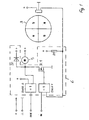
- Fig. 1 is a control device for at least one actuator 21 (see Fig.2) as Circuit arrangement shown in simplified form.
- 3 denotes a ring magnet, which is assigned a Hall switch 4.
- the ring magnet 3 has four poles here and executed symmetrically, the different polarity transitions N / S or Define S / N different switching points for Hall switch 4.
- An exit of the Hall switch 4 is connected to the input of an OR gate 1, the other Input from a separate control unit (not shown) with signals is applied.
- the OR gate 1 is an exclusive OR. About the resistance R1 are the Hall switch 4 and the one connected to the Hall switch 4 Input of the OR gate 1 at the positive voltage potential.
- a switching transistor Tr.1 is connected, via the one Motor 5 is switched or clocked.
- the OR gate 1 acts as a connecting link, ie as a comparator between the signals from the separate control device and the signals from the Hall switch 4 for the motor 5.
- the exclusive OR 1 only switches through if an inverse signal is supplied by the Hall switch 4 at this time.
- the motor 5 is controlled via the switching transistor Tr.1, the motor 5 in turn adjusting the position of the four-pole ring magnet 3 relative to the Hall switch 4 by adjusting the actuator 21 connected to the ring magnet 3.
- the polarity changes from, for example, N / S to S / N of the ring magnet 3 to the Hall switch 4.
- the segmented ring magnet 3 makes it possible to set the actuator 21 rotatable (360 °) and adjustable in one direction.
- FIG. 1 additionally shows a further OR gate 2, which input side with the drain of the switching transistor Tr.1 and the Motor input of motor 5 and connected to diode D1. Another entrance is connected to a signal path delivering a constant comparison signal.
- the Output of the OR gate 2 is provided as an output for an error message.
- so-called on-board diagnosis can also be carried out be carried out, whereby if the control malfunctions, e.g. of Motor 5, the magnet 3 and / or the Hall switch 4 etc. a constant, this Error-defining signal level, for example "high” at the "OUT" output is placed.
- FIG. 2 shows an application of the control device from FIG. 1 in or on an actuator 21 (simplified and slightly enlarged) shown.
- the aforementioned electrical components with the exception of the Hall switch 4, marked with 6, for example, manufactured in SMD technology and like the Hall switch 4 are located on a circuit board 7.
- the circuit board 7 is preferred arranged above the ring magnet 3.
- the ring magnet 3 is on a shaft 21.1 the actuator 21 attached.
- the Hall switch 4 In close proximity to the ring magnet 3 is the Hall switch 4.
- the motor 5 adjusts the actuator 21 until from Hall switch 4, as already described, a shutdown signal is output.
- the control device is also preferably designed as a module as a unit, whereby these can be quickly attached to the shaft 21.1 and easily connected electrically is what enables flexible use of the unit.
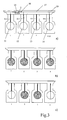
- Fig. 3 a) - c) are several, synchronous mutually adjustable actuators 11 to 14 in a common housing 10 integrated.
- Preferably is only a four-pole ring magnet 3 (Fig.1) and a control device used with a Hall switch 4. There is also the four-pole ring magnet 3 arranged on the shaft 11.1 of the first flap 11.
- a gear 15 and a Auger 16 Via a gear 15 and a Auger 16 (see Fig.3a) is the motor movement of preferably one Transfer motor 5 to shafts 11.1 to 14.1 evenly.
- the moveable Transmission to the waves 11.1 to 14.1 is carried out by levers (not shown) on the one hand with one of the shafts 11.1 to 14.1 and on the other hand with the central one Wave 16.1 are connected. The is located on the central shaft 16.1 Snail 16.
Landscapes
- Engineering & Computer Science (AREA)
- Chemical & Material Sciences (AREA)
- Combustion & Propulsion (AREA)
- Mechanical Engineering (AREA)
- General Engineering & Computer Science (AREA)
- Physics & Mathematics (AREA)
- General Physics & Mathematics (AREA)
- Transmission And Conversion Of Sensor Element Output (AREA)
- Measurement Of Length, Angles, Or The Like Using Electric Or Magnetic Means (AREA)
- Control Of Throttle Valves Provided In The Intake System Or In The Exhaust System (AREA)
Abstract
Description
- Fig. 1
- eine als Schaltung vereinfacht dargestellte Steuereinrichtung mit einem vierpoligen Ringmagneten und einem Hall-Schalter,
- Fig.2
- ein modularer Einbau der Steuereinrichttung in einem Stellorgan,
- Fig.3 a) - c)
- eine Anordnung der modularen Steuereinrichtung für mehrere Stellorgane, sowie Darstellung dieser in unterschiedlichen Stellungen,
- Fig. 4
- ein weiterer mehrfach segmentierter Magnet.
Mit Anliegen eines Stellsignals vom Steuergerät am ODER -Glied 1 schaltet das Exclusiv-ODER 1 nur dann durch, wenn zu diesem Zeitpunkt vom Hall-Schalter 4 ein inverses Signal geliefert wird. Mit Durchschaltung wird der Motor 5 über den Schalttransistor Tr.1 angesteuert, wobei der Motor 5 seinerseits durch Verstellung des mit dem Ringmagnet 3 verbunden Stellorgans 21 die Lage des vierpoligen Ringmagneten 3 zum Hall-Schalter 4 verstellt. Dabei verändert sich die Polungslage von beispielsweise N/S auf S/N des Ringmagneten 3 zum Hall-Schalter 4. Dies bewirkt, daß der Hall-Schalter 4 bei der Umpolungsphase , d.h. während der Polungsübergänge, schaltet und ein entsprechendes Signal an das ODER-Glied 1 gelangt, wodurch der Motor 5 abgeschaltet wird.
Bei Anliegen eines neuen Stellsignals vom Steuergerät wiederholt sich diese Prozedur, wobei der Hall-Schalter 4 erneut schaltet und dieser ein neues Signal an das ODER-Glied 1 gibt und der Motor 5 abgeschaltet wird. Das Exclusiv-ODER 1 bewirkt somit, daß trotz zweier unterschiedlicher Signale bzw. Schaltzustände (High, Low) des Hall-Schalters 4 der Motor 5 immer abgeschaltet werden kann. Insbesondere bei einem Neustart entfällt in vorteilhafter Art und Weise eine Abfrage des Schaltzustandes des Hall-Schalter 4 und damit eine Abfrage der aktuellen Stellung des Stellorgans.
Claims (6)
- Steuereinrichtung für ein Stellorgan, welches mit einer Welle verbunden ist, die von einem Motor zur Winkelverstellung des Stellorgans abgetrieben wird, dadurch gekennzeichnet, daßein segmentierter Magnet (3, 30) auf der Welle (21.1) des Stellorgans (21) angebracht ist, demwenigstens ein Hall-Schalter (4) derart zugeordnet ist, daß dieserbei Verstellung des Magneten (3) einen Polübergang (N/S, S/N) detektiert undden Motor (5) abschaltet.
- Steuereinrichtung für mehrere Stellorgane, die mit je einer Wellen verbunden sind und über diese verstellt werden, dadurch gekennzeichnet, daßdie Stellorgane (11 bis 14) synchron und zwangsgeführt über einen gemeinsamen Motor (5) verstellt werden, wozuein mehrpoliger Magnet (3, 30) an einer der Wellen (11.1 bis 14.1) befestigt ist, demwenigstens ein Hall-Schalter (4) zugeordnet ist, derbei Verstellung des einen Magneten (3) einen Polübergang (N/S, S/N) detektiert undden gemeinsamen Motor (5) abschaltet,.
- Steuereinrichtung nach Anspruch 1 oder 2, dadurch gekennzeichnet, daßdie Segmentierung des Magneten (3) von der Anzahl der Verstellung des Stellorgans (21, 11 bis 14) abhängig ist.
- Steuereinrichtung nach einem der Ansprüche 1 bis 3, dadurch gekennzeichnet, daßdie Steuereinrichtung eingangsseitig einen Vergleicher (ODER1) aufweist, über den das Verstellsignal als auch das Abschaltsignal für den Motor (5) ausgegeben wird, wozu der andere Eingang des Vergleichers (ODER1) vom Hall-Schalter (4) beaufschlagt wird.
- Steuereinrichtung nach einem der Ansprüche 1 bis 4, dadurch gekennzeichnet, daßdie Steuereinrichtung zur Fehlermeldung ausgangsseitig einen weiteren Vergleicher (ODER2) aufweist, der eingangsseitig einerseits mit dem Motor (5) und einem weiteren, ein konstantes Vergleichssignal liefernden Signalpfad verbunden ist.
- Steuereinrichtung nach einem der Ansprüche 1 bis 5, dadurch gekennzeichnet, daßder Magnet (3, 30) ein mehrpoliger Ringmagnet ist.
Applications Claiming Priority (2)
| Application Number | Priority Date | Filing Date | Title |
|---|---|---|---|
| DE10100966 | 2001-01-11 | ||
| DE2001100966 DE10100966A1 (de) | 2001-01-11 | 2001-01-11 | Steuereinrichtung für ein Stellorgan |
Publications (2)
| Publication Number | Publication Date |
|---|---|
| EP1223410A2 true EP1223410A2 (de) | 2002-07-17 |
| EP1223410A3 EP1223410A3 (de) | 2004-02-11 |
Family
ID=7670229
Family Applications (1)
| Application Number | Title | Priority Date | Filing Date |
|---|---|---|---|
| EP01127997A Withdrawn EP1223410A3 (de) | 2001-01-11 | 2001-11-24 | Steuereinrichtung für ein Stellorgan |
Country Status (2)
| Country | Link |
|---|---|
| EP (1) | EP1223410A3 (de) |
| DE (1) | DE10100966A1 (de) |
Cited By (4)
| Publication number | Priority date | Publication date | Assignee | Title |
|---|---|---|---|---|
| DE10304329A1 (de) * | 2003-02-04 | 2004-08-12 | Mann + Hummel Gmbh | Verstellvorrichtung |
| EP1333452A3 (de) * | 2002-02-01 | 2006-03-08 | Pierburg GmbH | Steuereinrichtung für einen Motor zur Verstellung eines Stellorgans |
| CN102360186A (zh) * | 2011-09-02 | 2012-02-22 | 天津津伯仪表技术有限公司 | 一种执行机构专用非接触式人机交互电路 |
| WO2016034373A1 (de) * | 2014-09-01 | 2016-03-10 | Igus Gmbh | Leitungsführungseinrichtung |
Families Citing this family (3)
| Publication number | Priority date | Publication date | Assignee | Title |
|---|---|---|---|---|
| DE10321653B3 (de) | 2003-05-14 | 2004-04-29 | Pierburg Gmbh | Stellvorrichtung für eine Verbrennungskraftmaschine |
| DE102004053703A1 (de) | 2004-11-06 | 2006-05-24 | Pierburg Gmbh | Stellvorrichtung für eine Verbrennungskraftmaschine |
| DE102011114681A1 (de) * | 2011-10-04 | 2013-05-08 | Rwe Power Aktiengesellschaft | Absperrarmatur |
Family Cites Families (4)
| Publication number | Priority date | Publication date | Assignee | Title |
|---|---|---|---|---|
| JPS5414827Y2 (de) * | 1975-02-20 | 1979-06-18 | ||
| US4829248A (en) * | 1984-09-20 | 1989-05-09 | Loubier Robert J | Hall effect sensing apparatus and method |
| DE19848081A1 (de) * | 1998-09-01 | 2000-03-02 | Mannesmann Vdo Ag | Antriebseinrichtung mit einem Stellantrieb |
| DE19842349B4 (de) * | 1998-09-16 | 2013-07-04 | Pierburg Gmbh | Abgasrückführsystem |
-
2001
- 2001-01-11 DE DE2001100966 patent/DE10100966A1/de not_active Withdrawn
- 2001-11-24 EP EP01127997A patent/EP1223410A3/de not_active Withdrawn
Cited By (7)
| Publication number | Priority date | Publication date | Assignee | Title |
|---|---|---|---|---|
| EP1333452A3 (de) * | 2002-02-01 | 2006-03-08 | Pierburg GmbH | Steuereinrichtung für einen Motor zur Verstellung eines Stellorgans |
| DE10304329A1 (de) * | 2003-02-04 | 2004-08-12 | Mann + Hummel Gmbh | Verstellvorrichtung |
| CN102360186A (zh) * | 2011-09-02 | 2012-02-22 | 天津津伯仪表技术有限公司 | 一种执行机构专用非接触式人机交互电路 |
| WO2016034373A1 (de) * | 2014-09-01 | 2016-03-10 | Igus Gmbh | Leitungsführungseinrichtung |
| CN107076265A (zh) * | 2014-09-01 | 2017-08-18 | 易格斯有限公司 | 管线引导装置 |
| US10378610B2 (en) | 2014-09-01 | 2019-08-13 | Igus Gmbh | Line guide device |
| EP3189568B1 (de) * | 2014-09-01 | 2020-07-08 | Igus GmbH | Leitungsführungseinrichtung |
Also Published As
| Publication number | Publication date |
|---|---|
| EP1223410A3 (de) | 2004-02-11 |
| DE10100966A1 (de) | 2002-07-18 |
Similar Documents
| Publication | Publication Date | Title |
|---|---|---|
| DE112006001967B4 (de) | Schaukelvorrichtung mit einer Schaltung zum Erzeugen einer Abstoßkraft | |
| EP1917167B9 (de) | Elektromotorischer hilfsantrieb für fahrzeuge | |
| EP1477649B1 (de) | Stellvorrichtung für eine Verbrennungskraftmaschine | |
| DE10153727A1 (de) | Schrittmotor | |
| DE60207899T2 (de) | Schaltaktuator für Getriebe | |
| DE19754843A1 (de) | Antriebsvorrichtung für ein zwischen Endstellungen bewegbares Teil eines Fahrzeugs und Verfahren zu ihrer Herstellung | |
| DE1463495A1 (de) | Endlagensteuereinheit | |
| EP2436021B1 (de) | Schalteinheit für einen schutzschalter mit kipphebel | |
| DE10100966A1 (de) | Steuereinrichtung für ein Stellorgan | |
| DE2637326C2 (de) | Scheinwerfernivelliersystem für ein Kraftfahrzeug und elektrischer Schalter zur Verwendung in einem solchen System | |
| DE1813591A1 (de) | Zuendvorrichtung fuer Verbrennungsmotoren | |
| EP1825222A1 (de) | Schaltklappeneinrichtung | |
| EP1333452B1 (de) | Steuereinrichtung für einen Motor zur Verstellung eines Stellorgans | |
| EP1719009B1 (de) | Verfahren zur steuerung eines lichtverschlusses | |
| EP1088952B1 (de) | Kraftfahrzeug-Türschloss | |
| DE2321403C3 (de) | Antriebseinrichtung für einen Schieber | |
| EP0770329A1 (de) | System für Walzspalteinstellung | |
| EP1805844B1 (de) | Elektrische schaltvorrichtung mit magnetischen verstellelementen | |
| DE102017211893B4 (de) | Verstellanordnung für ein Drehschiebermodul sowie Drehschiebermodul mit einer solchen Verstellanordnung | |
| EP0484834A1 (de) | Vorrichtung zur Drehwinkelpositionierung einer mit Exzenterorganen versehenen Welle | |
| DE19923746A1 (de) | Drehkolbenventil mit elektromotorischem Stellantrieb | |
| DE102024129568B4 (de) | Relais | |
| DE4024910C1 (en) | Setter drive for motor vehicle central locking system - uses electromotors controlled via limit switch with pivoted contact bridge | |
| DE10339457A1 (de) | Stellantrieb mit Steuereinheit und Verfahren zum Betreiben des Stellantriebs | |
| DE8801632U1 (de) | Stellantrieb, insbesondere für ein Stellglied einer Heizungsanlage |
Legal Events
| Date | Code | Title | Description |
|---|---|---|---|
| PUAI | Public reference made under article 153(3) epc to a published international application that has entered the european phase |
Free format text: ORIGINAL CODE: 0009012 |
|
| 17P | Request for examination filed |
Effective date: 20011124 |
|
| AK | Designated contracting states |
Kind code of ref document: A2 Designated state(s): AT BE CH CY DE DK ES FI FR GB GR IE IT LI LU MC NL PT SE TR |
|
| AX | Request for extension of the european patent |
Free format text: AL;LT;LV;MK;RO;SI |
|
| RAP1 | Party data changed (applicant data changed or rights of an application transferred) |
Owner name: PIERBURG GMBH |
|
| PUAL | Search report despatched |
Free format text: ORIGINAL CODE: 0009013 |
|
| STAA | Information on the status of an ep patent application or granted ep patent |
Free format text: STATUS: THE APPLICATION HAS BEEN WITHDRAWN |
|
| AK | Designated contracting states |
Kind code of ref document: A3 Designated state(s): AT BE CH CY DE DK ES FI FR GB GR IE IT LI LU MC NL PT SE TR |
|
| AX | Request for extension of the european patent |
Extension state: AL LT LV MK RO SI |
|
| RIC1 | Information provided on ipc code assigned before grant |
Ipc: 7G 01D 5/14 B Ipc: 7F 02D 11/10 A |
|
| 18W | Application withdrawn |
Effective date: 20040114 |