EP1223291B2 - Verbinder mit Stanzschraube - Google Patents
Verbinder mit Stanzschraube Download PDFInfo
- Publication number
- EP1223291B2 EP1223291B2 EP02000186A EP02000186A EP1223291B2 EP 1223291 B2 EP1223291 B2 EP 1223291B2 EP 02000186 A EP02000186 A EP 02000186A EP 02000186 A EP02000186 A EP 02000186A EP 1223291 B2 EP1223291 B2 EP 1223291B2
- Authority
- EP
- European Patent Office
- Prior art keywords
- connector
- punching screw
- legs
- counter
- screw
- Prior art date
- Legal status (The legal status is an assumption and is not a legal conclusion. Google has not performed a legal analysis and makes no representation as to the accuracy of the status listed.)
- Expired - Lifetime
Links
Images



Classifications
-
- E—FIXED CONSTRUCTIONS
- E06—DOORS, WINDOWS, SHUTTERS, OR ROLLER BLINDS IN GENERAL; LADDERS
- E06B—FIXED OR MOVABLE CLOSURES FOR OPENINGS IN BUILDINGS, VEHICLES, FENCES OR LIKE ENCLOSURES IN GENERAL, e.g. DOORS, WINDOWS, BLINDS, GATES
- E06B3/00—Window sashes, door leaves, or like elements for closing wall or like openings; Layout of fixed or moving closures, e.g. windows in wall or like openings; Features of rigidly-mounted outer frames relating to the mounting of wing frames
- E06B3/96—Corner joints or edge joints for windows, doors, or the like frames or wings
- E06B3/964—Corner joints or edge joints for windows, doors, or the like frames or wings using separate connection pieces, e.g. T-connection pieces
- E06B3/9642—Butt type joints with at least one frame member cut off square; T-shape joints
-
- F—MECHANICAL ENGINEERING; LIGHTING; HEATING; WEAPONS; BLASTING
- F16—ENGINEERING ELEMENTS AND UNITS; GENERAL MEASURES FOR PRODUCING AND MAINTAINING EFFECTIVE FUNCTIONING OF MACHINES OR INSTALLATIONS; THERMAL INSULATION IN GENERAL
- F16B—DEVICES FOR FASTENING OR SECURING CONSTRUCTIONAL ELEMENTS OR MACHINE PARTS TOGETHER, e.g. NAILS, BOLTS, CIRCLIPS, CLAMPS, CLIPS OR WEDGES; JOINTS OR JOINTING
- F16B2/00—Friction-grip releasable fastenings
- F16B2/02—Clamps, i.e. with gripping action effected by positive means other than the inherent resistance to deformation of the material of the fastening
- F16B2/04—Clamps, i.e. with gripping action effected by positive means other than the inherent resistance to deformation of the material of the fastening internal, i.e. with spreading action
-
- F—MECHANICAL ENGINEERING; LIGHTING; HEATING; WEAPONS; BLASTING
- F16—ENGINEERING ELEMENTS AND UNITS; GENERAL MEASURES FOR PRODUCING AND MAINTAINING EFFECTIVE FUNCTIONING OF MACHINES OR INSTALLATIONS; THERMAL INSULATION IN GENERAL
- F16B—DEVICES FOR FASTENING OR SECURING CONSTRUCTIONAL ELEMENTS OR MACHINE PARTS TOGETHER, e.g. NAILS, BOLTS, CIRCLIPS, CLAMPS, CLIPS OR WEDGES; JOINTS OR JOINTING
- F16B7/00—Connections of rods or tubes, e.g. of non-circular section, mutually, including resilient connections
- F16B7/04—Clamping or clipping connections
- F16B7/044—Clamping or clipping connections for rods or tubes being in angled relationship
- F16B7/0446—Clamping or clipping connections for rods or tubes being in angled relationship for tubes using the innerside thereof
- F16B7/0473—Clamping or clipping connections for rods or tubes being in angled relationship for tubes using the innerside thereof with hook-like parts gripping, e.g. by expanding, behind the flanges of a profile
Definitions
- the invention relates to connectors with punching screw, as they are known, for example, for the installation of rungs in windows.
- a connector is described for example in the processing guidelines WICLINE 60, page 82 by the applicant.
- Such a connector corresponds to the preamble of claim 1.
- This prior art connector is formed einklipsbar; the punching screw is inserted through the axial bore in the connector head and screwed between the outer ends of the connector legs, so that the punch pin penetrates the component to be connected and the punching screw fixes the outwardly claw-shaped leg ends in the corresponding profile of the component to be connected.
- the loose punching screw is mounted on a hex key, inserted through the axial bore in the head portion of the connector to between the leg ends of the connector and screwed here.
- the object of the invention is to overcome these disadvantages and in particular to provide connectors that allow assembly automation.
- the generic connector is tweezer-shaped and has two mutually resilient leg 3; these are hook-shaped in their foot region 6 facing outwards to form a profile.
- the loose punching screw 5 is placed on a hex key, inserted through the opening 4 of the axial bore through the connector head 2 and screwed in the foot area 6 for fixing the connector with the profile.
- FIGS. 2a to 2c A preferred embodiment of the connector according to the invention is shown schematically in FIGS. 2a to 2c.
- the punching screw 5 is releasably fixed in the head portion 2 of the connector 1 within the axial bore. This can be done for example by jamming or gluing the screw head 5a in the bore.
- notches or burrs 5 b are provided either on the outer edge of the screw head 5 a or within the bore 4, which are dimensioned in such a way that the screw head 5 a is jammed in the bore 4, but displaceable against axial pressure is.
- the bore 4 can additionally serve as a control of the exact axial insertion in the foot 6 of the connector 1.
- thread and counter-thread can be designed such that the screw head 5a is held with a half turn in the internal thread in the central bore, while after another half turn freely and without further rotation axially in the direction of the hook-shaped leg ends 7 is feasible.
- FIGS. 3 a and 3 b show a further preferred embodiment of the connector according to the invention in a schematic side view.
- the reference numerals unless otherwise indicated, the same components as in Figure 1.
- the punching screw 5 between the legs 3 of the connector 1 is releasably supported or supported.
- the mounting device on the inside of a leg 3 has a web 9, which projects into the space between the legs 3 and a plastic nut 8 or an O-ring 10 which holds the screw shaft or the screw head 5a releasably, so that at axial Force the punching screw 5 can be guided and screwed between the hook-shaped ends 7 of the legs 3.
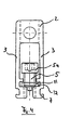
- Figure 4 shows a schematic side view of a further preferred embodiment of the connector according to the invention, wherein the punching screw 5 is formed such that it can be inserted laterally clamped in the space between the legs 3 of the connector 1.
- a bead-shaped ring 11 may be provided, which removably surrounds the circumference of the punching screw shaft, and the material (rubber, foam) and / or dimensionally selected such that it is in a groove-shaped Recess 12 can be inserted into the inner side walls of the legs 3 and under axial pressure on the punching screw 5 can pass through the punching screw shaft.
- Figure 5 shows a further preferred embodiment in which within the connector body a web 9 is provided which has an opening with internal thread 9a in the middle, said internal thread corresponds to the external thread of the punching screw 5, so that the punching screw 5 is screwed into this opening 9a and thereby is held there, wherein in the assembly, the punching screw 5 is moved by screws between the connector legs 3 for spreading the legs 3 and the screw in the profile part.
- FIG. 6 shows a preferred solution in which an opening with internal thread 13a is arranged in the remaining wall 13 between the countersink and the chamber of the connector, the internal thread 13a corresponding to the external thread of the punching screw 5, and this being comparable, as in FIG. mounted in the thread 13a and is movable in the axial direction by screwing.
Landscapes
- Engineering & Computer Science (AREA)
- General Engineering & Computer Science (AREA)
- Mechanical Engineering (AREA)
- Civil Engineering (AREA)
- Structural Engineering (AREA)
- Dowels (AREA)
- Mutual Connection Of Rods And Tubes (AREA)
- Surgical Instruments (AREA)
- Adornments (AREA)
- Multi-Conductor Connections (AREA)
- Coupling Device And Connection With Printed Circuit (AREA)
- Connection Of Batteries Or Terminals (AREA)
- Structures For Mounting Electric Components On Printed Circuit Boards (AREA)
Description
- Die Erfindung betrifft Verbinder mit Stanzschraube, wie sie beispielsweise zum Einbau von Sprossen bei Fenstern bekannt sind. Ein solcher Verbinder wird beispielsweise in den Verarbeitungsrichtlinien WICLINE 60, Seite 82 von der Anmelderin beschrieben. Ein solcher Verbinder entspricht dem Oberbegriff des Anspruchs 1.
- Dieser vorbekannte Verbinder ist einklipsbar ausgebildet; die Stanzschraube wird durch die axiale Bohrung im Verbinderkopf eingeführt und zwischen den äußeren Enden der Verbinderschenkel verschraubt, so daß der Stanzstift das zu verbindende Bauteil durchtritt und die Stanzschraube die nach außen krallenförmig ausgebildeten Schenkelenden im entsprechenden Profil des zu verbindenden Bauteils fixiert.
- Bei der Montage wird die lose Stanzschraube auf einen Sechskantschlüssel aufgesteckt, durch die axiale Bohrung im Kopfteil des Verbinders bis zwischen die Schenkelenden des Verbinders eingeführt und hier verschraubt.
- Nachteilig an dieser Lösung ist der Umstand, daß auf diese Weise eine Montageautomatisierung nicht erfolgen kann; darüberhinaus erfordert die notwendige Handarbeit erhebliches Geschick; schließlich tritt bei hohem Arbeitsdruck häufig Verlust der Stanzschraube auf.
- Aufgabe der Erfindung ist es, diese Nachteile zu überwinden und insbesondere Verbinder zur Verfügung zu stellen, die Montageautomatisierung ermöglichen.
- Diese erfindungsgemäße Aufgabe wird durch den Verbinder gemäß Anspruch 1, 4, 5 oder 6 gelöst; die Ansprüche 2 und 3 betreffen weitere vorteilhafte Ausgestaltungen der Erfindung.
- Die Erfindung wird anhand der folgenden Figuren näher erläutert. Hierbei zeigen die
- Figuren 1a und 1b schematisch einen Verbinder aus dem Stand der Technik;
- Figuren 2a bis 2c eine bevorzugte Ausführungsform eines erfindungsgemäßen Verbinders;
- Figuren 3a und 3b eine weitere erfindungsgemäße Ausführungsform;
- Figur 4 eine andere erfindungsgemäße Ausführungsform;
- Figur 5 zeigt eine weitere erfindungsgemäße Ausführungsform, bei der die Stanzschraube in einem Gewinde gelagert ist; und
- Figur 6 eine andere Ausführungsform der Lösung nach Figur 5.
- Gemäß Figuren 1a und 1b ist der gattungsgemäße Verbinder pinzettenförmig ausgebildet und weist zwei gegeneinander federnde Schenkel 3 auf; diese sind in ihrem Fußbereich 6 hakenförmig 7 nach außen weisend zur Unterfassung eines Profils ausgebildet. Die lose Stanzschraube 5 wird auf einen Sechskantschlüssel aufgesetzt, durch die Öffnung 4 der axialen Bohrung durch den Verbinderkopf 2 eingeführt und im Fußbereich 6 zur Fixierung des Verbinders mit dem Profil verschraubt.
- In den Figuren 2a bis 2c wird eine bevorzugte Ausführungsform des erfindungsgemäßen Verbinders schematisch wiedergegeben. Hierbei ist die Stanzschraube 5 im Kopfbereich 2 des Verbinders 1 innerhalb der axialen Bohrung lösbar fixiert. Dieses kann beispielsweise durch Verklemmen oder Verkleben des Schraubenkopfes 5a in der Bohrung erfolgen. Bei der Ausführung gemäß den Figuren 2b und 2c sind entweder am äußeren Rand des Schraubenkopfes 5a oder innerhalb der Bohrung 4 Kerbungen bzw. Grate 5b vorgesehen, die dimensionsmäßig derart ausgebildet sind, daß der Schraubenkopf 5a in der Bohrung 4 verklemmt, jedoch gegen axialen Druck verschiebbar ist. Hierbei kann die Bohrung 4 zusätzlich als Steuerung des exakten axialen Einschubs in den Fuß 6 des Verbinders 1 dienen.
- Ebenfalls kann vorgesehen sein, daß am Schraubenkopf 5a außen ein nach oben und unten offenes kurzes Gewinde angeordnet ist, das mit einem gleichen Gegengewinde im inneren der zentralen Bohrung zusammenwirkt. Hierbei können beispielsweise Gewinde und Gegengewinde derart ausgebildet sein, daß der Schraubenkopf 5a mit einer halben Drehung im Innengewinde in der zentralen Bohrung gehaltert wird, während er nach einer weiteren halben Drehung frei und ohne weitere Drehung axial in Richtung auf die hakenförmigen Schenkelenden 7 führbar ist.
- In den Figuren 3a und 3b ist eine weitere bevorzugte Ausführungsform des erfindungsgemäßen Verbinders in schematischer Seitenansicht wiedergegeben. Auch hier betreffen die Bezugszeichen, sofern nichts anderes angegeben, die gleichen Bauteile wie in Figur 1. Bei dieser Ausführungsform ist die Stanzschraube 5 zwischen den Schenkeln 3 des Verbinders 1 lösbar gelagert bzw. gehaltert. Die Halterungsvorrichtung an der Innenseite eines Schenkels 3 weist einen Steg 9 auf, der in den Freiraum zwischen den Schenkeln 3 hineinragt und eine Kunststoffmutter 8 oder einen O-Ring 10 aufweist, die den Schraubenschaft bzw. den Schraubenkopf 5a lösbar haltert, so daß bei axialer Krafteinwirkung die Stanzschraube 5 zwischen die hakenförmigen Enden 7 der Schenkel 3 geführt und eingeschraubt werden kann.
- Figur 4 zeigt in schematischer Seitenansicht eine weitere bevorzugte Ausführungsform des erfindungsgemäßen Verbinders, wobei die Stanzschraube 5 derart ausgebildet ist, daß sie seitwärts in den Freiraum zwischen den Schenkeln 3 des Verbinders 1 verklemmbar eingeschoben werden kann. Hierbei kann ein wulstförmiger Ring 11 vorgesehen sein, der den Umfang des Stanzschraubenschaftes lösbar umschließt, und der materialmäßig (Gummi, Schaumstoff) und/oder dimensionsmäßig derart gewählt ist, daß er in eine nutenförmige Ausnehmung 12 in den inneren Seitenwänden der Schenkel 3 eingesteckt werden kann und unter axialem Druck auf die Stanzschraube 5 den Stanzschraubenschaft durchgleiten läßt.
- Figur 5 zeigt eine weitere bevorzugte Ausführungsform, bei der innerhalb des Verbinderkörpers ein Steg 9 vorgesehen ist, der mittig eine Öffnung mit Innengewinde 9a aufweist, wobei dieses Innengewinde dem Außengewinde der Stanzschraube 5 entspricht, so daß die Stanzschraube 5 in diese Öffnung 9a eingeschraubt und hierdurch dort gehaltert wird, wobei bei der Montage die Stanzschraube 5 durch Schrauben zwischen die Verbinderschenkel 3 zur Aufspreizung der Schenkel 3 und zur Verschraubung im Profilteil bewegt wird.
- Schließlich zeigt Figur 6 eine bevorzugte Lösung, bei der in der verbleibenden Wand 13 zwischen Senkung und Kammer des Verbinders eine Öffnung mit Innengewinde 13a angeordnet ist, wobei das Innengewinde 13a dem Außengewinde der Stanzschraube 5 entspricht, und wobei diese, vergleichbar wie in Figur 5, im Gewinde 13a gelagert und in axialer Richtung durch Schraubbewegung bewegbar ist.
Claims (6)
- Verbinder mit Stanzschraube (5), wobei- der Verbinder pinzettenförmig mit zwei gegeneinander federnden Schenkel (3) ausgebildet ist,- der Kopfbereich (2) des Verbinders die Öffnung einer zentralen Längsbohrung zum Einschub der Stanzschraube (5) aufweist und- die Schenkel (3) im Fußbereich des Verbinders hakenförmig, nach außen weisend und gegeneinander federnd ausgebildet sind,- dadurch gekennzeichnet, dass- die Stanzschraube (5) innerhalb des Verbinderkörpers (1) an ihrem Kopf (5a) im Kopfbereich (2) des Verbinders in axialer Richtung beweglich oder lösbar gelagert ist, ohne hierbei das Gegeneinandegedern der Schenkel (3), zu behindern und die Stanzschraube (5) im Fußbereich des Verbinders zur fixierung des Verbinders mit einem Profil verschraubar ist.
- Verbinder nach Anspruch 1 dadurch gekennzeichnet, dass der Kopf (5a) der Stanzschraube (5) in der Längsbohrung im Kopfbereich (2) des Verbinders lösbar verklemmt oder verklebt ist.
- Verbinder nach Anspruch 1 dadurch gekennzeichnet, dass der Kopf (5a) der Stanzschraube (5) ein kurzes Außengewinde aufweist, das mit einem Innengewinde der Längsbohrung im Kopfbereich (2) des Verbinders zusammenwirkt.
- Verbinder mit Stanzschraube (5), wobei- der Verbinder pinzettenförmig mit zwei gegeneinander federnden Schenkeln (3) ausgebildet ist,- der Kopfbereich (2) des Verbinders die Öffnung einer zentralen Längsbohrung zum Einschub der Stanzschraube (5) aufweist und- die Schenkel (3) im Fußbereich des Verbinders hakenförmig nach außen weisend und gegeneinander federnd ausgebildet sind,- dadurch gekennzeichnet, dass- die Stanzschraube (5) innerhalb des Verbinderkörpers (1) in axialer Richtung beweglich oder lösbar gelagert ist, ohne hierbei das Gegeneinanderfedern der Schenkel (3) zu behindern, und- die Stanzschraube (5) zwischen den Schenkeln (3) mittels einer Kunststoffmutter (8) oder eines O-Ringes (10) gehalten ist, die bzw. der auf einem innerhalb eines Schenkels (3) angepressten Steg (9) fixiert ist, und die Stanzschraube (5) im Fußbereich des Verbinders zur Fixierung des Verbinders mit einem Profil verschraubar ist.
- Verbinder mit Stanzschraube (5), wobei- der Verbinder pinzettenförmig mit zwei gegeneinander federnden Schenkeln (3) ausgebildet ist,- der Kopfbereich (2) des Verbinders die Öffnung einer zentralen Längsbohrung zum Einschub der Stanzschraube (5) aufweist und- die Schenkel (3) im Fußbereich des Verbinders hakenförmig, nach außen weisend und gegeneinander federnd ausgebildet sind,- dadurch gekennzeichnet, dass- die Stanzschraube (5) innerhalb des Verbinderkörpers (1) in axialer Richtung beweglich oder lösbar gelagert ist ohne hierbei das gegeneinander Federn der Schenkel zu behindern,- die Stanzschraube (5) einen umlaufenden, wulstförmigen Ring (11) aufweist, der in eine Nut (12) verklemmend eingeschoben ist, die zwischen den Schenkeln (3) ausgebildet ist, und die Stanzschraube (5) im Fußbereich des Verbinders zur Fixierung des Verbinders mit einem Profil verschaubar ist.
- Verbinder mit Stanzschraube (5), wobei- der Verbinder pinzettenförmig mit zwei gegeneinander federnden Schenkeln (3) ausgebildet ist,- der Kopfbereich (2) des Verbinders die Öffnung einer zentralen Längsbohrung zum Einschub der Stanzschraube (5) aufweist und- die Schenkel (3) im Fußbereich des Verbinders hakenförmig nach außen weisend und gegeneinander federnd ausgebildet sind- dadurch gekennzeichnet, dass- die Stanzschraube (5) innerhalb des Verbinderkörpers (1) in axialer Richtung beweglich oder lösbar gelagert ist, ohne hierbei das gegeneinander Federn der Schenkel zu behindern,- innerhalb des Verbinderkörpers (1) ein Steg (9) mit einer Öffnung mit Innengewinde (9a) vorgesehen ist, das dem Außengewinde der Stanzschraube (5) entspricht und in dem die Stanzschraube (5) gelagert und in axialer Richtung durch Schraubbewegung bewegbar ist derart, dass durch die Schraubbewegung der Stanzschraube (5) die Schenkel (3) aufgespreizt werden, und die Stanzschraube (5) in einem Innengewinde im Fußbereich des Verbinders zur Fixierung des Verbinders mit einem Profil verschraubar ist.
Applications Claiming Priority (2)
| Application Number | Priority Date | Filing Date | Title |
|---|---|---|---|
| DE10101201A DE10101201A1 (de) | 2001-01-11 | 2001-01-11 | Verbinder mit Stanzschraube |
| DE10101201 | 2001-01-11 |
Publications (3)
| Publication Number | Publication Date |
|---|---|
| EP1223291A1 EP1223291A1 (de) | 2002-07-17 |
| EP1223291B1 EP1223291B1 (de) | 2003-08-13 |
| EP1223291B2 true EP1223291B2 (de) | 2007-05-23 |
Family
ID=7670364
Family Applications (1)
| Application Number | Title | Priority Date | Filing Date |
|---|---|---|---|
| EP02000186A Expired - Lifetime EP1223291B2 (de) | 2001-01-11 | 2002-01-09 | Verbinder mit Stanzschraube |
Country Status (5)
| Country | Link |
|---|---|
| EP (1) | EP1223291B2 (de) |
| AT (1) | ATE247217T1 (de) |
| DE (2) | DE10101201A1 (de) |
| ES (1) | ES2204869T5 (de) |
| PT (1) | PT1223291E (de) |
Families Citing this family (7)
| Publication number | Priority date | Publication date | Assignee | Title |
|---|---|---|---|---|
| DE202006003166U1 (de) * | 2006-03-01 | 2006-05-24 | Hydro Building Systems Gmbh | Lamellenanordnung für Fassaden |
| DE102007052672B4 (de) * | 2007-11-05 | 2016-12-01 | Airbus Operations Gmbh | Rumpfzellenstruktur eines Flugzeugs zur vereinfachten Verlegung und Befestigung von Haltern zur Befestigung von Leitungen |
| DE102014111089A1 (de) * | 2014-08-05 | 2016-02-11 | Hueck Gmbh & Co. Kg | Profilanordnung |
| CN105822196B (zh) * | 2016-06-14 | 2017-10-03 | 无锡王兴幕墙装饰工程有限公司 | 十字连接结构 |
| CN107719271B (zh) * | 2017-08-24 | 2020-01-21 | 安徽江淮汽车集团股份有限公司 | 一种汽车诊断接口插件的配合结构 |
| IT202000018049A1 (it) * | 2020-07-24 | 2022-01-24 | L M Dei F Lli Monticelli S R L | Kit comprendente un profilato ed un tassello ad espansione. |
| CN112227902A (zh) * | 2020-12-15 | 2021-01-15 | 湖南亘晟门窗幕墙有限公司 | 自动调平的铝合金门窗中梃连接结构及拆装方法 |
Family Cites Families (8)
| Publication number | Priority date | Publication date | Assignee | Title |
|---|---|---|---|---|
| US3752032A (en) * | 1971-07-08 | 1973-08-14 | T Fiddler | Self attaching coupling |
| JPS5422839Y2 (de) * | 1971-11-11 | 1979-08-08 | ||
| DE2236321C3 (de) * | 1972-07-25 | 1981-09-24 | SCHÜCO Heinz Schürmann GmbH & Co, 4800 Bielefeld | T-förmig verbundene Profile oder Rohre |
| DE2913281C2 (de) * | 1979-04-03 | 1982-08-26 | W. Hartmann & Co (Gmbh & Co), 2000 Hamburg | Stoßverbindung eines Kämpferprofils mit einem Rahmen- oder Sprossenprofil für Fenster, Türen o.dgl. |
| DE3716617C1 (en) * | 1987-05-18 | 1988-08-25 | Wieland Werke Ag | Heat-insulated window or door frame having at least one transom profile |
| US5020951A (en) * | 1990-10-05 | 1991-06-04 | Smith David G | Fastener assembly |
| DE19534034A1 (de) * | 1995-09-14 | 1997-03-20 | Mann & Hummel Filter | Befestigungsvorrichtung |
| DE19750658C1 (de) * | 1997-11-15 | 1999-03-11 | Gloeckler Dichtsysteme Guenter | Verbindungselement |
-
2001
- 2001-01-11 DE DE10101201A patent/DE10101201A1/de not_active Withdrawn
-
2002
- 2002-01-09 ES ES02000186T patent/ES2204869T5/es not_active Expired - Lifetime
- 2002-01-09 EP EP02000186A patent/EP1223291B2/de not_active Expired - Lifetime
- 2002-01-09 AT AT02000186T patent/ATE247217T1/de active
- 2002-01-09 DE DE50200025T patent/DE50200025D1/de not_active Expired - Lifetime
- 2002-01-09 PT PT02000186T patent/PT1223291E/pt unknown
Also Published As
| Publication number | Publication date |
|---|---|
| DE50200025D1 (de) | 2003-09-18 |
| ES2204869T3 (es) | 2004-05-01 |
| EP1223291A1 (de) | 2002-07-17 |
| DE10101201A1 (de) | 2002-08-01 |
| PT1223291E (pt) | 2003-11-28 |
| ATE247217T1 (de) | 2003-08-15 |
| EP1223291B1 (de) | 2003-08-13 |
| ES2204869T5 (es) | 2007-11-16 |
Similar Documents
| Publication | Publication Date | Title |
|---|---|---|
| DE2527404C3 (de) | Vorrichtung zur schnellen Befestigung an einer Wand, insbesondere fur den Durchtritt eines Kabels | |
| EP3004702B1 (de) | Kombination aus einem gehäuse und einem ventil | |
| EP1223291B1 (de) | Verbinder mit Stanzschraube | |
| DE10148943B4 (de) | Schraubvorrichtung für Schraubendreher-Einsätze | |
| DE102004001788A1 (de) | Anordnung zur axial verstellbaren Halterung eines berührungslos arbeitenden Sensors | |
| DE60038654T2 (de) | Klemmhalterung für Stütz- und Verbindungselemente | |
| EP0252208A1 (de) | Fluidbetätigter Zylinder | |
| EP0968793A2 (de) | Variables Schraub- und/oder Bohrwerkzeug | |
| DE102006050651B3 (de) | Pneumatisches 5/3-Wegeventil in Schieberbauweise | |
| EP3507508A1 (de) | Drehverschluss zur verbindung von bauteilen | |
| DE10254999B4 (de) | Montageeinheit | |
| EP1361325A1 (de) | Betätiger für Verschlüsse an Fahrzeugen | |
| EP3828426B1 (de) | Verbindungselement für mehrkantrohre | |
| DE102007007636B3 (de) | Abzieher | |
| DE3421560C2 (de) | ||
| DE3338217C2 (de) | Konterwerkzeug für Schraubverbindungen mit unterschiedlich großen Mehrkant-Mitnahmekörpern | |
| DE10001264C1 (de) | Einstellvorrichtung für Türscharniere, insbesondere an Kraftfahrzeugtüren | |
| DE102021123121A1 (de) | Werkstückanschlag und Spannvorrichtung mit Werkstückanschlag | |
| DE102013110907B4 (de) | Nutenstein | |
| WO2022090183A1 (de) | Schraubendrehereinsatz | |
| EP3537017A1 (de) | Ventil | |
| DE20218204U1 (de) | Halterung für Magnetfeldsensoren | |
| EP1084660B1 (de) | Vorrichtung zur vertikalen Einstellung für Möbelschubladen | |
| DE2529131C2 (de) | Befestigungselement zur Befestigung eines Zylinderdeckels | |
| DE2534375C2 (de) | Stiftförmige Vorrichtung zum federnden Verspannen zweier Bauteile |
Legal Events
| Date | Code | Title | Description |
|---|---|---|---|
| PUAI | Public reference made under article 153(3) epc to a published international application that has entered the european phase |
Free format text: ORIGINAL CODE: 0009012 |
|
| AK | Designated contracting states |
Kind code of ref document: A1 Designated state(s): AT BE CH CY DE DK ES FI FR GB GR IE IT LI LU MC NL PT SE TR |
|
| AX | Request for extension of the european patent |
Free format text: AL;LT;LV;MK;RO;SI |
|
| GRAH | Despatch of communication of intention to grant a patent |
Free format text: ORIGINAL CODE: EPIDOS IGRA |
|
| 17P | Request for examination filed |
Effective date: 20021218 |
|
| RAP1 | Party data changed (applicant data changed or rights of an application transferred) |
Owner name: NORSK HYDRO ASA |
|
| AKX | Designation fees paid |
Designated state(s): AT BE CH CY DE DK ES FI FR GB GR IE IT LI LU MC NL PT SE TR |
|
| GRAS | Grant fee paid |
Free format text: ORIGINAL CODE: EPIDOSNIGR3 |
|
| GRAA | (expected) grant |
Free format text: ORIGINAL CODE: 0009210 |
|
| AK | Designated contracting states |
Designated state(s): AT BE CH CY DE DK ES FI FR GB GR IE IT LI LU MC NL PT SE TR |
|
| PG25 | Lapsed in a contracting state [announced via postgrant information from national office to epo] |
Ref country code: FI Free format text: LAPSE BECAUSE OF FAILURE TO SUBMIT A TRANSLATION OF THE DESCRIPTION OR TO PAY THE FEE WITHIN THE PRESCRIBED TIME-LIMIT Effective date: 20030813 Ref country code: IE Free format text: LAPSE BECAUSE OF FAILURE TO SUBMIT A TRANSLATION OF THE DESCRIPTION OR TO PAY THE FEE WITHIN THE PRESCRIBED TIME-LIMIT Effective date: 20030813 Ref country code: CY Free format text: LAPSE BECAUSE OF FAILURE TO SUBMIT A TRANSLATION OF THE DESCRIPTION OR TO PAY THE FEE WITHIN THE PRESCRIBED TIME-LIMIT Effective date: 20030813 Ref country code: TR Free format text: LAPSE BECAUSE OF FAILURE TO SUBMIT A TRANSLATION OF THE DESCRIPTION OR TO PAY THE FEE WITHIN THE PRESCRIBED TIME-LIMIT Effective date: 20030813 |
|
| REG | Reference to a national code |
Ref country code: GB Ref legal event code: FG4D Free format text: NOT ENGLISH |
|
| REG | Reference to a national code |
Ref country code: CH Ref legal event code: EP |
|
| REG | Reference to a national code |
Ref country code: IE Ref legal event code: FG4D Free format text: GERMAN |
|
| REF | Corresponds to: |
Ref document number: 50200025 Country of ref document: DE Date of ref document: 20030918 Kind code of ref document: P |
|
| REG | Reference to a national code |
Ref country code: CH Ref legal event code: NV Representative=s name: PATENTANWAELTE SCHAAD, BALASS, MENZL & PARTNER AG |
|
| PG25 | Lapsed in a contracting state [announced via postgrant information from national office to epo] |
Ref country code: DK Free format text: LAPSE BECAUSE OF FAILURE TO SUBMIT A TRANSLATION OF THE DESCRIPTION OR TO PAY THE FEE WITHIN THE PRESCRIBED TIME-LIMIT Effective date: 20031113 Ref country code: GR Free format text: LAPSE BECAUSE OF FAILURE TO SUBMIT A TRANSLATION OF THE DESCRIPTION OR TO PAY THE FEE WITHIN THE PRESCRIBED TIME-LIMIT Effective date: 20031113 |
|
| REG | Reference to a national code |
Ref country code: SE Ref legal event code: TRGR |
|
| GBT | Gb: translation of ep patent filed (gb section 77(6)(a)/1977) | ||
| PG25 | Lapsed in a contracting state [announced via postgrant information from national office to epo] |
Ref country code: LU Free format text: LAPSE BECAUSE OF NON-PAYMENT OF DUE FEES Effective date: 20040109 |
|
| PG25 | Lapsed in a contracting state [announced via postgrant information from national office to epo] |
Ref country code: MC Free format text: LAPSE BECAUSE OF NON-PAYMENT OF DUE FEES Effective date: 20040131 |
|
| REG | Reference to a national code |
Ref country code: IE Ref legal event code: FD4D |
|
| REG | Reference to a national code |
Ref country code: ES Ref legal event code: FG2A Ref document number: 2204869 Country of ref document: ES Kind code of ref document: T3 |
|
| PLBQ | Unpublished change to opponent data |
Free format text: ORIGINAL CODE: EPIDOS OPPO |
|
| PLBI | Opposition filed |
Free format text: ORIGINAL CODE: 0009260 |
|
| ET | Fr: translation filed | ||
| PLAX | Notice of opposition and request to file observation + time limit sent |
Free format text: ORIGINAL CODE: EPIDOSNOBS2 |
|
| 26 | Opposition filed |
Opponent name: SCHUECO INTERNATIONAL KG Effective date: 20040511 |
|
| NLR1 | Nl: opposition has been filed with the epo |
Opponent name: SCHUECO INTERNATIONAL KG |
|
| PLBB | Reply of patent proprietor to notice(s) of opposition received |
Free format text: ORIGINAL CODE: EPIDOSNOBS3 |
|
| PUAH | Patent maintained in amended form |
Free format text: ORIGINAL CODE: 0009272 |
|
| STAA | Information on the status of an ep patent application or granted ep patent |
Free format text: STATUS: PATENT MAINTAINED AS AMENDED |
|
| 27A | Patent maintained in amended form |
Effective date: 20070523 |
|
| AK | Designated contracting states |
Kind code of ref document: B2 Designated state(s): AT BE CH CY DE DK ES FI FR GB GR IE IT LI LU MC NL PT SE TR |
|
| REG | Reference to a national code |
Ref country code: CH Ref legal event code: AEN Free format text: AUFRECHTERHALTUNG DES PATENTES IN GEAENDERTER FORM |
|
| NLR2 | Nl: decision of opposition |
Effective date: 20070523 |
|
| GBTA | Gb: translation of amended ep patent filed (gb section 77(6)(b)/1977) | ||
| REG | Reference to a national code |
Ref country code: SE Ref legal event code: RPEO |
|
| NLR3 | Nl: receipt of modified translations in the netherlands language after an opposition procedure | ||
| ET3 | Fr: translation filed ** decision concerning opposition | ||
| REG | Reference to a national code |
Ref country code: ES Ref legal event code: DC2A Date of ref document: 20070628 Kind code of ref document: T5 |
|
| PGFP | Annual fee paid to national office [announced via postgrant information from national office to epo] |
Ref country code: PT Payment date: 20110104 Year of fee payment: 10 |
|
| PGFP | Annual fee paid to national office [announced via postgrant information from national office to epo] |
Ref country code: ES Payment date: 20110125 Year of fee payment: 10 |
|
| REG | Reference to a national code |
Ref country code: PT Ref legal event code: MM4A Free format text: LAPSE DUE TO NON-PAYMENT OF FEES Effective date: 20120709 |
|
| PG25 | Lapsed in a contracting state [announced via postgrant information from national office to epo] |
Ref country code: PT Free format text: LAPSE BECAUSE OF NON-PAYMENT OF DUE FEES Effective date: 20120709 |
|
| PGFP | Annual fee paid to national office [announced via postgrant information from national office to epo] |
Ref country code: SE Payment date: 20130122 Year of fee payment: 12 |
|
| REG | Reference to a national code |
Ref country code: ES Ref legal event code: FD2A Effective date: 20130708 |
|
| PG25 | Lapsed in a contracting state [announced via postgrant information from national office to epo] |
Ref country code: ES Free format text: LAPSE BECAUSE OF NON-PAYMENT OF DUE FEES Effective date: 20120110 |
|
| PGFP | Annual fee paid to national office [announced via postgrant information from national office to epo] |
Ref country code: NL Payment date: 20130418 Year of fee payment: 12 |
|
| REG | Reference to a national code |
Ref country code: DE Ref legal event code: R082 Ref document number: 50200025 Country of ref document: DE Representative=s name: KOTITSCHKE & HEURUNG PARTNERSCHAFT MBB PATENT-, DE |
|
| REG | Reference to a national code |
Ref country code: NL Ref legal event code: V1 Effective date: 20140801 |
|
| REG | Reference to a national code |
Ref country code: SE Ref legal event code: EUG |
|
| REG | Reference to a national code |
Ref country code: CH Ref legal event code: PUE Owner name: SAPA AS, NO Free format text: FORMER OWNER: NORSK HYDRO ASA, NO |
|
| REG | Reference to a national code |
Ref country code: DE Ref legal event code: R082 Ref document number: 50200025 Country of ref document: DE Representative=s name: KOTITSCHKE & HEURUNG PARTNERSCHAFT MBB PATENT-, DE |
|
| PG25 | Lapsed in a contracting state [announced via postgrant information from national office to epo] |
Ref country code: NL Free format text: LAPSE BECAUSE OF NON-PAYMENT OF DUE FEES Effective date: 20140801 |
|
| REG | Reference to a national code |
Ref country code: DE Ref legal event code: R082 Ref document number: 50200025 Country of ref document: DE Effective date: 20140109 Ref country code: DE Ref legal event code: R082 Ref document number: 50200025 Country of ref document: DE Effective date: 20141017 Ref country code: DE Ref legal event code: R082 Ref document number: 50200025 Country of ref document: DE Representative=s name: KOTITSCHKE & HEURUNG PARTNERSCHAFT MBB PATENT-, DE Effective date: 20141017 Ref country code: DE Ref legal event code: R082 Ref document number: 50200025 Country of ref document: DE Representative=s name: KOTITSCHKE & HEURUNG PARTNERSCHAFT MBB PATENT-, DE Effective date: 20140109 Ref country code: DE Ref legal event code: R081 Ref document number: 50200025 Country of ref document: DE Owner name: SAPA AS, NO Free format text: FORMER OWNER: NORSK HYDRO ASA, OSLO, NO Effective date: 20141017 |
|
| PG25 | Lapsed in a contracting state [announced via postgrant information from national office to epo] |
Ref country code: SE Free format text: LAPSE BECAUSE OF NON-PAYMENT OF DUE FEES Effective date: 20140110 |
|
| REG | Reference to a national code |
Ref country code: DE Ref legal event code: R082 Ref document number: 50200025 Country of ref document: DE |
|
| REG | Reference to a national code |
Ref country code: GB Ref legal event code: 732E Free format text: REGISTERED BETWEEN 20141127 AND 20141203 |
|
| REG | Reference to a national code |
Ref country code: FR Ref legal event code: TP Owner name: SAPA AS, NO Effective date: 20150120 |
|
| REG | Reference to a national code |
Ref country code: AT Ref legal event code: PC Ref document number: 247217 Country of ref document: AT Kind code of ref document: T Owner name: SAPA AS, NO Effective date: 20150818 |
|
| REG | Reference to a national code |
Ref country code: FR Ref legal event code: PLFP Year of fee payment: 15 |
|
| PGFP | Annual fee paid to national office [announced via postgrant information from national office to epo] |
Ref country code: CH Payment date: 20160120 Year of fee payment: 15 |
|
| PGFP | Annual fee paid to national office [announced via postgrant information from national office to epo] |
Ref country code: AT Payment date: 20160121 Year of fee payment: 15 |
|
| REG | Reference to a national code |
Ref country code: FR Ref legal event code: PLFP Year of fee payment: 16 |
|
| REG | Reference to a national code |
Ref country code: CH Ref legal event code: PL |
|
| REG | Reference to a national code |
Ref country code: AT Ref legal event code: MM01 Ref document number: 247217 Country of ref document: AT Kind code of ref document: T Effective date: 20170109 |
|
| PG25 | Lapsed in a contracting state [announced via postgrant information from national office to epo] |
Ref country code: AT Free format text: LAPSE BECAUSE OF NON-PAYMENT OF DUE FEES Effective date: 20170109 Ref country code: CH Free format text: LAPSE BECAUSE OF NON-PAYMENT OF DUE FEES Effective date: 20170131 Ref country code: LI Free format text: LAPSE BECAUSE OF NON-PAYMENT OF DUE FEES Effective date: 20170131 |
|
| REG | Reference to a national code |
Ref country code: FR Ref legal event code: PLFP Year of fee payment: 17 |
|
| PGFP | Annual fee paid to national office [announced via postgrant information from national office to epo] |
Ref country code: IT Payment date: 20180122 Year of fee payment: 17 |
|
| PG25 | Lapsed in a contracting state [announced via postgrant information from national office to epo] |
Ref country code: IT Free format text: LAPSE BECAUSE OF NON-PAYMENT OF DUE FEES Effective date: 20190109 |
|
| PGFP | Annual fee paid to national office [announced via postgrant information from national office to epo] |
Ref country code: FR Payment date: 20210118 Year of fee payment: 20 |
|
| PGFP | Annual fee paid to national office [announced via postgrant information from national office to epo] |
Ref country code: DE Payment date: 20210121 Year of fee payment: 20 Ref country code: BE Payment date: 20210120 Year of fee payment: 20 Ref country code: GB Payment date: 20210120 Year of fee payment: 20 |
|
| REG | Reference to a national code |
Ref country code: DE Ref legal event code: R082 Ref document number: 50200025 Country of ref document: DE Representative=s name: EISENFUEHR SPEISER PATENTANWAELTE RECHTSANWAEL, DE |
|
| REG | Reference to a national code |
Ref country code: DE Ref legal event code: R071 Ref document number: 50200025 Country of ref document: DE |
|
| REG | Reference to a national code |
Ref country code: GB Ref legal event code: PE20 Expiry date: 20220108 |
|
| REG | Reference to a national code |
Ref country code: BE Ref legal event code: MK Effective date: 20220109 |
|
| PG25 | Lapsed in a contracting state [announced via postgrant information from national office to epo] |
Ref country code: GB Free format text: LAPSE BECAUSE OF EXPIRATION OF PROTECTION Effective date: 20220108 |