EP1223228A2 - Induktionsglühe - Google Patents
Induktionsglühe Download PDFInfo
- Publication number
- EP1223228A2 EP1223228A2 EP01129967A EP01129967A EP1223228A2 EP 1223228 A2 EP1223228 A2 EP 1223228A2 EP 01129967 A EP01129967 A EP 01129967A EP 01129967 A EP01129967 A EP 01129967A EP 1223228 A2 EP1223228 A2 EP 1223228A2
- Authority
- EP
- European Patent Office
- Prior art keywords
- induction
- wire
- short
- voltage
- primary windings
- Prior art date
- Legal status (The legal status is an assumption and is not a legal conclusion. Google has not performed a legal analysis and makes no representation as to the accuracy of the status listed.)
- Granted
Links
Images




Classifications
-
- C—CHEMISTRY; METALLURGY
- C21—METALLURGY OF IRON
- C21D—MODIFYING THE PHYSICAL STRUCTURE OF FERROUS METALS; GENERAL DEVICES FOR HEAT TREATMENT OF FERROUS OR NON-FERROUS METALS OR ALLOYS; MAKING METAL MALLEABLE, e.g. BY DECARBURISATION OR TEMPERING
- C21D9/00—Heat treatment, e.g. annealing, hardening, quenching or tempering, adapted for particular articles; Furnaces therefor
- C21D9/52—Heat treatment, e.g. annealing, hardening, quenching or tempering, adapted for particular articles; Furnaces therefor for wires; for strips ; for rods of unlimited length
- C21D9/54—Furnaces for treating strips or wire
- C21D9/56—Continuous furnaces for strip or wire
- C21D9/60—Continuous furnaces for strip or wire with induction heating
-
- B—PERFORMING OPERATIONS; TRANSPORTING
- B21—MECHANICAL METAL-WORKING WITHOUT ESSENTIALLY REMOVING MATERIAL; PUNCHING METAL
- B21C—MANUFACTURE OF METAL SHEETS, WIRE, RODS, TUBES, PROFILES OR LIKE SEMI-MANUFACTURED PRODUCTS OTHERWISE THAN BY ROLLING; AUXILIARY OPERATIONS USED IN CONNECTION WITH METAL-WORKING WITHOUT ESSENTIALLY REMOVING MATERIAL
- B21C47/00—Winding-up, coiling or winding-off metal wire, metal band or other flexible metal material characterised by features relevant to metal processing only
- B21C47/26—Special arrangements with regard to simultaneous or subsequent treatment of the material
-
- C—CHEMISTRY; METALLURGY
- C21—METALLURGY OF IRON
- C21D—MODIFYING THE PHYSICAL STRUCTURE OF FERROUS METALS; GENERAL DEVICES FOR HEAT TREATMENT OF FERROUS OR NON-FERROUS METALS OR ALLOYS; MAKING METAL MALLEABLE, e.g. BY DECARBURISATION OR TEMPERING
- C21D9/00—Heat treatment, e.g. annealing, hardening, quenching or tempering, adapted for particular articles; Furnaces therefor
- C21D9/52—Heat treatment, e.g. annealing, hardening, quenching or tempering, adapted for particular articles; Furnaces therefor for wires; for strips ; for rods of unlimited length
- C21D9/525—Heat treatment, e.g. annealing, hardening, quenching or tempering, adapted for particular articles; Furnaces therefor for wires; for strips ; for rods of unlimited length for wire, for rods
-
- C—CHEMISTRY; METALLURGY
- C21—METALLURGY OF IRON
- C21D—MODIFYING THE PHYSICAL STRUCTURE OF FERROUS METALS; GENERAL DEVICES FOR HEAT TREATMENT OF FERROUS OR NON-FERROUS METALS OR ALLOYS; MAKING METAL MALLEABLE, e.g. BY DECARBURISATION OR TEMPERING
- C21D9/00—Heat treatment, e.g. annealing, hardening, quenching or tempering, adapted for particular articles; Furnaces therefor
- C21D9/52—Heat treatment, e.g. annealing, hardening, quenching or tempering, adapted for particular articles; Furnaces therefor for wires; for strips ; for rods of unlimited length
- C21D9/54—Furnaces for treating strips or wire
- C21D9/56—Continuous furnaces for strip or wire
- C21D9/573—Continuous furnaces for strip or wire with cooling
- C21D9/5732—Continuous furnaces for strip or wire with cooling of wires; of rods
-
- Y—GENERAL TAGGING OF NEW TECHNOLOGICAL DEVELOPMENTS; GENERAL TAGGING OF CROSS-SECTIONAL TECHNOLOGIES SPANNING OVER SEVERAL SECTIONS OF THE IPC; TECHNICAL SUBJECTS COVERED BY FORMER USPC CROSS-REFERENCE ART COLLECTIONS [XRACs] AND DIGESTS
- Y02—TECHNOLOGIES OR APPLICATIONS FOR MITIGATION OR ADAPTATION AGAINST CLIMATE CHANGE
- Y02P—CLIMATE CHANGE MITIGATION TECHNOLOGIES IN THE PRODUCTION OR PROCESSING OF GOODS
- Y02P10/00—Technologies related to metal processing
- Y02P10/25—Process efficiency
Definitions
- the invention relates to an induction annealing for conductive Heating a wire with the in the preamble of claim 1 specified features.
- Such an induction glow is known from DE 39 20 139 A1.
- a wire to be heat-treated is placed over two in mutually spaced rollers guided in a loop.
- One of these roles serves as a short circuit role, over which the wire both when entering the loop and when Leaving the loop and which one electrically conductive connection between the incoming and the expiring area so that around the two roles looped wire loop a self-contained conductor loop forms.
- the wire runs between the two rollers in two parallel straight sections, one of which by two induction heaters arranged one behind the other that induce a voltage in the wire loop, which has an appropriate current for heating the wire lets flow.
- the short-circuit roller also serves as a cooling roller for the leaking wire.
- the generation is problematic with such induction annealing a sufficiently high induction voltage in the wire loop, to enter the required glow power and the setting the induction voltage.
- Other problems are the optimized Size between the electrical and mechanical components as well as the impairments of the efficiency or Reactive power due to leakage inductances.
- the invention has for its object such an induction annealing to improve in that at relatively handy Size and very good efficiency also for high-impedance Sufficiently high induction voltage in the wire loop can be achieved, which occur in a wide range leaves to very different wire materials and -to be able to optimally subject dimensions to heat treatment.
- the magnetic cores of the Transformers run as a secondary turn and are heated together become.
- the magnetic cores can be rectangular in this case be shaped to accommodate a larger number of parallel Pick up wires.
- the wires can be round or in cross section be rectangular or flat (ribbons).
- a desired large setting range for the induction voltage is achieved according to the invention by controlling the Primary windings with pulses that have an adjustability of several Allow parameters such as curve shape, amplitude, width and frequency.
- Symmetrical, bipolar pulses are preferred because the occurrence of a DC component in the Can avoid primary windings, which an undesirable bias the cores would result in the usable headroom would limit the magnetic characteristic.
- a converter from the three-phase network or another source supplied AC voltage produces a wavy or smoothed DC voltage, the size of which made adjustable as intermediate circuit voltage if necessary becomes.
- This DC voltage can then be used in a suitable manner Way controllable inverter adjustable in bipolar pulses Convert waveform, frequency and width while the pulse amplitude over the DC link voltage can be adjusted.
- the output from the inverter to the transformers of the glow Power can be adjusted by adjusting the voltage in the DC link for example by setting the ignition angle in the line-side converter or by an inserted step-down or Step-up converter can be effected or by changing the Duty cycle of the valves in the inverter are brought about, what to change the time course of the inverter output voltage and thus changes in their effective value leads, the frequency of the output voltage and its im Effective value provided by the inverter using a suitable control device can be specified.
- These multiple setting parameters allow a considerable expansion of the setting range for the voltage induced in the wire loop, so that even with very different wire materials and dimensions always choose the optimal treatment temperature can.
- the circuit is expediently designed so that the transformers can be individually switched to the setting options the respective resistance conditions of the wire material and the wire speed in stages as far as possible to be able to adapt, in addition to the setting options of Power supply (via the level of the DC link voltage and / or via the pulse width and / or via the inverter frequency) still about the choice (number) of partial voltages, which the individual core packages induce influence on the annealing parameters can be taken.
- a favorable, preferred frequency range for the pulses lies between about 4 and 12 kHz and above.
- Leave with the arrangement according to the invention powers in a wide range of, for example, 3 kW up to 120 kW and above in the wire loop to their Transfer heating.
- a cooling nozzle with which the heat-treated Wire immediately before exiting the loop is cooled again and the short-circuit roller is not heated unnecessarily becomes the wire can expediently still provided by a behind the short circuit role Blow-off nozzle to be blown dry to get out of the cooling nozzle to remove carried-over coolant.
- the wire By means of the short-circuit roller 4, the wire also becomes one deflected here not illustrated winding device, wherein made contact with the incoming wire via the short-circuit roller is so that the loop 6 short-circuited in itself is.
- the inductor 8 basically consists of a magnetic Toroid on which a primary winding is wound and through the wire loop 6 as a short-circuited single-winding secondary winding runs. When feeding the primary winding with a AC voltage induces a voltage corresponding to the turns ratio Secondary voltage that flow a secondary current lets, which heats the wire in the wire loop 6.
- the schematically indicated primary winding is at 16 and it feeding current source designated 18.
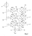
- FIG. 2 the embodiment of such is now Induction annealing illustrated.
- three core packages 22 composed of ring cores 20 are shown: in the illustrated case, each package consists of three Toroids.
- the core packages 22 are arranged coaxially with one another, so that the wire 2 in the loop 6 the packets one after the other passes.
- the packets 22 are each associated with one Primary winding 16 is wound, and the three primary windings are connected to the power source 18 via leads 24. This delivers Pulses to feed the primary windings, and each primary winding induces a voltage contribution in the wire loop 6: these voltage contributions add up to a total voltage as loop voltage, which the corresponding current for Heating of the wire flows.
- the voltage source 18 for feeding the primary windings 16 exists according to the invention from a rectifier 26 for the AC line voltage, which in the case shown from a three-phase network 28 is removed.
- the one available in an intermediate circuit 30 DC voltage is converted into an inverter 32 pulse-shaped alternating voltage, which is converted via the supply line 24 the three primary windings 16 is supplied.
- the power source 18 Be via a switching device 34 the three phases of the three-phase network, one rectifier each (Power converter) 26a, 26b and 26c supplied, which here as switching power supplies SNT1, SNT2 and SNT3 are formed and one each Deliver DC voltage to an intermediate circuit 30a, 30b or 30c.
- the level of this DC voltage is with the help of a control signal U adjustable by a control signal generator 36.
- the intermediate circles 30a, 30b and 30c are here through storage capacitors C1, C2 and C3 illustrated.
- the DC voltages will be Inverters 32a, 32b and 32c supplied and from these in Pulse voltages u11, u12 and u13 converted, their shape, Width and frequency are controlled by control signals SS1, SS2 and SS3 can be varied by a control device 38 to the effective value to change the pulse voltage.
- control signals SS1, SS2 and SS3 can be varied by a control device 38 to the effective value to change the pulse voltage.
- the output voltages u11, u12 and u13 are the three primary windings 16 supplied in which thereupon primary currents i11, i12 or i13 flow. Induce these primary currents as I said in the secondary winding of this transformer forming wire loop 6 corresponding induction voltage components, which are in the loop for total loop tension add up, which in turn corresponds to the wire resistance Current flows in the loop.
- Fig. 4 shows a core package composed of three toroidal cores 20a, 20b and 20c 22, on which the primary winding 16 is drawn with four Is wound.
- Fig. 5 shows these turns for themselves, so that all turns are visible.
- the winding sections running over the end faces of the core package are designated in sequence with 40a to 40h, where sections 40a, 40c, 40e and 40g the upper and 40b, 40d, 40f and 40h are the lower sections.
- the outside or inside on Core vertical sections are of interest not designated the clarity of the figure.
- the windings of the primary winding are laid sinoid to a multifarious training of the primary winding overlap to avoid.
- This winding training is in Fig. 6 illustrates in which it can be seen that the individual Winding sections 40a to 40h (in the polar coordinate system) are formed by sections of a sine function.
- FIGS. 7 and 8 A trifilar winding is illustrated in FIGS. 7 and 8, in which the monofilar windings of Figures 4 to 6 in are designated in the same way, while those in between For the sake of clarity, turns are not specifically designated. Leave through the multifilament training of the primary winding the leakage inductances are kept low, so that the primary power fed into the core package largely without loss is and as induction power for the secondary current in the Wire loop 6 is available.
- the described embodiment a trifilar winding does not mean any Limitation of the invention, but if necessary other multifilament windings are also used.
Landscapes
- Engineering & Computer Science (AREA)
- Chemical & Material Sciences (AREA)
- Mechanical Engineering (AREA)
- Materials Engineering (AREA)
- Crystallography & Structural Chemistry (AREA)
- Thermal Sciences (AREA)
- Physics & Mathematics (AREA)
- Metallurgy (AREA)
- Organic Chemistry (AREA)
- General Induction Heating (AREA)
- Heat Treatment Of Strip Materials And Filament Materials (AREA)
- Crystals, And After-Treatments Of Crystals (AREA)
- Soft Magnetic Materials (AREA)
Abstract
Description
- Fig. 1
- eine Darstellung zur Veranschaulichung des Prinzips einer Induktionsglühe;
- Fig. 2
- eine Prinzipdarstellung der erfindungsgemäßen Induktionsglühe mit drei Transformatoren;
- Fig. 3
- ein Schaltungsbeispiel für die Stromquelle, hier zur getrennten Speisung der drei Primärwicklungen gemäß Fig. 2;
- Fig. 4
- ein aus drei Magnetkernen aufgebautes Kernpaket mit einer zu Veranschaulichungszwecken nur monofilaren Primärwicklung;
- Fig. 5
- die herausgezeichnete Wicklung ohne Kern;
- Fig. 6
- eine Skizze zur Veranschaulichung der sinoidalen Wicklung;
- Fig. 7
- das Kernpaket gemäß Fig. 4 mit einer trifilaren Wicklung; und
- Fig. 8
- eine Draufsicht auf das bewickelte Kernpaket gemäß Fig. 7.
Claims (11)
- Induktionsglühe zur konduktiven Erwärmung mindestens eines Drahtes, mit mehreren Transformatoren, deren parallel angesteuerte Primärwicklungen um jeweils einen eigenen Magnetkern gewickelt sind und deren Sekundärwicklungen durch eine gemeinsame in sich kurzgeschlossene Drahtschleife gebildet werden, in welcher der Draht mit Hilfe von Umlenkrollen nacheinander durch die Magnetkerne geführt wird, sowie mit einer Kühlvorrichtung für den wärmebehandelten Draht und einer Spannungsquelle zur Speisung der Primärwicklungen,
dadurch gekennzeichnet, daß jeder Magnetkern durch ein Paket (22) aus mehreren Ringkernen (20) aus hochpermeablem Material mit hoher Sättigungsinduktion gebildet wird,
daß die Primärwicklungen (16) als multifilare Wicklungen ausgebildet sind,
daß die Kühlvorrichtung (14) als vom Draht (2) durchsetzte Kühldüse ausgebildet ist und in der Kurzschlußschleife (6) angeordnet ist,
und daß die Spannungsquelle (18) bipolare, symmetrische Spannungsimpulse beliebigen Zeitverlaufs, aber z.B. über Amplitude, Breite und/oder Frequenz einstellbaren Effektivwertes liefert. - Induktionsglühe nach Anspruch 1, dadurch gekennzeichnet, daß die Primärwicklungen (16) sinoidal gewickelt sind.
- Induktionsglühe nach Anspruch 1 oder 2, dadurch gekennzeichnet, daß die Primärwicklungen (16) mit HF-Litze gewickelt sind.
- Induktionsglühe nach Anspruch 1, dadurch gekennzeichnet, daß die Ringkerne (20) durch Schnitt- oder Ringbandkerne oder aus Blechen gestapelten Kernen gebildet werden.
- Induktionsglühe nach Anspruch 1, bei der die Kurzschlußschleife (6) durch eine Führung des einlaufenden Drahtes (2) über eine Kurzschlußrolle (4), eine Umlenkrolle (10) und zurück zur Kurzschlußrolle zum Drahtauslauf gebildet wird, dadurch gekennzeichnet, daß die Kühldüse (14) in der Kurzschlußschleife (6) kurz vor der Kurzschlußrolle (4) angeordnet ist.
- Induktionsglühe nach Anspruch 5, gekennzeichnet durch eine nach der Kurzschlußrolle (4) vorgesehene Abblasdüse (17) für den auslaufenden Draht.
- Induktionsglühe nach Anspruch 1, dadurch gekennzeichnet, daß die Spannungsquelle (18) durch einen aus dem Wechselstromnetz gespeisten Stromrichter (26) zur Lieferung einer einstellbaren Gleichspannung an einen Zwischenkreis (30) und einen mit dieser Gleichspannung gespeisten, bipolare symmetrische Spannungsimpulse einstellbaren Effektivwertes erzeugenden Wechselrichter (32) aufweist.
- Induktionsglühe nach Anspruch 7, dadurch gekennzeichnet, daß die Kurvenform und/oder Amplitude und/oder Frequenz und/oder Breite der Spannungsimpulse einstellbar ist.
- Induktionsglühe nach einem der vorstehenden Ansprüche, dadurch gekennzeichnet, daß jeder Transformator (20,22) einzeln zuschaltbar ist.
- Induktionsglühe nach einem der vorstehenden Ansprüche, zur Wärmebehandlung mehrerer unabhängiger Drähte, dadurch gekennzeichnet, daß die Drähte über unabhängige Rollensysteme gemeinsam durch die Magnetkerne geführt werden.
- Induktionsglühe nach Anspruch 10, dadurch gekennzeichnet, daß die Magnetkerne eine Rechteckform haben.
Applications Claiming Priority (2)
| Application Number | Priority Date | Filing Date | Title |
|---|---|---|---|
| DE10100829 | 2001-01-10 | ||
| DE10100829A DE10100829C1 (de) | 2001-01-10 | 2001-01-10 | Induktionsglühe |
Publications (3)
| Publication Number | Publication Date |
|---|---|
| EP1223228A2 true EP1223228A2 (de) | 2002-07-17 |
| EP1223228A3 EP1223228A3 (de) | 2004-06-16 |
| EP1223228B1 EP1223228B1 (de) | 2005-07-06 |
Family
ID=7670138
Family Applications (1)
| Application Number | Title | Priority Date | Filing Date |
|---|---|---|---|
| EP01129967A Expired - Lifetime EP1223228B1 (de) | 2001-01-10 | 2001-12-17 | Induktionsglühe |
Country Status (4)
| Country | Link |
|---|---|
| EP (1) | EP1223228B1 (de) |
| AT (1) | ATE299191T1 (de) |
| DE (2) | DE10100829C1 (de) |
| ES (1) | ES2243383T3 (de) |
Cited By (3)
| Publication number | Priority date | Publication date | Assignee | Title |
|---|---|---|---|---|
| CN111270052A (zh) * | 2020-03-27 | 2020-06-12 | 丰城市顺达五金制品有限公司 | 一种用于合金钢带的降温改良型热处理设备及合金钢带热处理工艺 |
| CN113817912A (zh) * | 2021-10-25 | 2021-12-21 | 太原工业学院 | 刚性防火电缆在线变频退火装置 |
| CN120290868A (zh) * | 2025-06-11 | 2025-07-11 | 太原科技大学 | 一种金属棒材双端全周向自适应脉冲电流处理装置及方法 |
Families Citing this family (4)
| Publication number | Priority date | Publication date | Assignee | Title |
|---|---|---|---|---|
| DE10326668B4 (de) * | 2003-06-13 | 2005-05-04 | Wieland-Werke Ag | Glühvorrichtung für metallisches Halbzeug |
| DE102004034939B4 (de) * | 2004-07-20 | 2015-11-26 | Maschinenfabrik Niehoff Gmbh & Co. Kg | Verfahren und Anordnung sowie Computerprogramm mit Programmcode-Mitteln und Computerprogramm-Produkt zur Ermittlung einer Steuergröße für einen Leistungseintrag auf einen Draht bei einer konduktiven Wärmebehandlung des Drahtes |
| GB2447963B (en) | 2007-03-29 | 2011-11-16 | E2V Tech | High frequency transformer for high voltage applications |
| CH702902A2 (de) | 2010-03-18 | 2011-09-30 | Buehrer Traktorenfabrik Ag | Verfahren und Vorrichtung zum Erwärmen von langgestreckten Erzeugnissen aus Metall. |
Family Cites Families (12)
| Publication number | Priority date | Publication date | Assignee | Title |
|---|---|---|---|---|
| US2448009A (en) * | 1944-02-05 | 1948-08-31 | Westinghouse Electric Corp | Inductive heating of longitudinally moving metal strip |
| US2773161A (en) * | 1954-05-25 | 1956-12-04 | Westinghouse Electric Corp | Combination control system for continuous heat treatment |
| DE1142209B (de) * | 1957-12-26 | 1963-01-10 | American Mach & Foundry | Einrichtung zur Waermebehandlung von Draht od. dgl. |
| FR2288152A1 (fr) * | 1974-10-18 | 1976-05-14 | Trefimetaux | Procede et appareillage pour le traitement thermique en continu des fils et bandes metalliques |
| JPS5214943A (en) * | 1975-07-28 | 1977-02-04 | Nippon Steel Corp | Uniform heating method using induction heating |
| JPS6032960B2 (ja) * | 1977-10-12 | 1985-07-31 | 古河電気工業株式会社 | 複数本の走行電線の誘導加熱方法 |
| US4506131A (en) * | 1983-08-29 | 1985-03-19 | Inductotherm Industries Inc. | Multiple zone induction coil power control apparatus and method |
| US4863145A (en) * | 1987-07-28 | 1989-09-05 | Wst Power Electronics, Inc. | Cooling wheel for annealing wire |
| GB8815371D0 (en) * | 1988-06-28 | 1988-08-03 | Beta Instr Co | Method & apparatus for heating metallic elongated product in motion |
| DD288989A5 (de) * | 1989-11-16 | 1991-04-18 | ����������@�����������@���Kk�� | Kuehlrohr |
| DE19527827C2 (de) * | 1995-07-29 | 1998-02-12 | Kuka Schweissanlagen & Roboter | Verfahren und Einrichtung zur Erzeugung elektrischer Wärme |
| JPH11172402A (ja) * | 1997-12-05 | 1999-06-29 | Mitsubishi Heavy Ind Ltd | 高品位亜鉛めっき鋼板の合金化装置及び加熱制御装置 |
-
2001
- 2001-01-10 DE DE10100829A patent/DE10100829C1/de not_active Expired - Fee Related
- 2001-12-17 ES ES01129967T patent/ES2243383T3/es not_active Expired - Lifetime
- 2001-12-17 AT AT01129967T patent/ATE299191T1/de active
- 2001-12-17 EP EP01129967A patent/EP1223228B1/de not_active Expired - Lifetime
- 2001-12-17 DE DE50106683T patent/DE50106683D1/de not_active Expired - Lifetime
Cited By (3)
| Publication number | Priority date | Publication date | Assignee | Title |
|---|---|---|---|---|
| CN111270052A (zh) * | 2020-03-27 | 2020-06-12 | 丰城市顺达五金制品有限公司 | 一种用于合金钢带的降温改良型热处理设备及合金钢带热处理工艺 |
| CN113817912A (zh) * | 2021-10-25 | 2021-12-21 | 太原工业学院 | 刚性防火电缆在线变频退火装置 |
| CN120290868A (zh) * | 2025-06-11 | 2025-07-11 | 太原科技大学 | 一种金属棒材双端全周向自适应脉冲电流处理装置及方法 |
Also Published As
| Publication number | Publication date |
|---|---|
| ES2243383T3 (es) | 2005-12-01 |
| ATE299191T1 (de) | 2005-07-15 |
| DE50106683D1 (de) | 2005-08-11 |
| DE10100829C1 (de) | 2002-05-08 |
| EP1223228B1 (de) | 2005-07-06 |
| EP1223228A3 (de) | 2004-06-16 |
Similar Documents
| Publication | Publication Date | Title |
|---|---|---|
| DE69512217T2 (de) | Direktwirkendes berührungloses elektrisches leistungskabel | |
| DE69103969T2 (de) | Induktionsheizspule. | |
| AT282011B (de) | Verfahren und Anordnungen zur Induktionsheizung | |
| AT522345B1 (de) | Heizungsvorrichtung zum induktiven Erhitzen eines Flachstahlstreifens in einem Warmwalzwerk | |
| DE102009013103B4 (de) | Anlage mit über den Boden bewegbaren Fahrzeugen | |
| DE3040028C2 (de) | HF-Siegeleinrichtung zum Versiegeln von Verpackungsmaterial | |
| DE69636524T2 (de) | Impededanzanpassungsapparat zum verbinden eines hochfrequenzhalbleiter-leistungsgenerators zu einer last | |
| EP1431986A1 (de) | Spulenanordnung mit veränderbarer Induktivität | |
| DE3118554A1 (de) | Stromversorgungsschaltung | |
| WO2013000593A1 (de) | Flachspule für kontaktlose induktive energieübertragung | |
| WO1995028723A1 (de) | Übertragungseinrichtung | |
| DE2824326A1 (de) | Stromversorgung fuer elektrische bearbeitung | |
| DE69517756T2 (de) | Stromversorgungssystem für funkenerosionmaschine | |
| EP1223228B1 (de) | Induktionsglühe | |
| DE2609971C3 (de) | Gleichstrom-Lichtbogenschweißgerät für Betrieb mit hochfrequentem Impulsstrom | |
| DE2908696C2 (de) | ||
| DE19527827A1 (de) | Verfahren und Einrichtung zur Erzeugung elektrischer Wärme | |
| DE4041448C2 (de) | ||
| DE3415967C2 (de) | ||
| EP1314339A1 (de) | Vorrichtung zur induktiven erwärmung von metallischen bändern | |
| DE4122601A1 (de) | Linearbeschleuniger | |
| DE69201617T2 (de) | Verfahren und anlage zum vermindern von abstandsabhängiger spannungserhöhung bei parallelen hochfrequenzelektroden. | |
| EP3420570B1 (de) | Elektrisches hochspannungsgerät mit einer regelwicklungsgruppe | |
| DE69213155T2 (de) | Induktionsanordnung zum Heizen von Metallbändern | |
| DE759835C (de) | UEbertrager mit Eisenkern und mit einem festen, von 1 abweichenden UEbersetzungsverhaeltnis |
Legal Events
| Date | Code | Title | Description |
|---|---|---|---|
| PUAI | Public reference made under article 153(3) epc to a published international application that has entered the european phase |
Free format text: ORIGINAL CODE: 0009012 |
|
| AK | Designated contracting states |
Kind code of ref document: A2 Designated state(s): AT BE CH CY DE DK ES FI FR GB GR IE IT LI LU MC NL PT SE TR |
|
| AX | Request for extension of the european patent |
Free format text: AL;LT;LV;MK;RO;SI |
|
| PUAL | Search report despatched |
Free format text: ORIGINAL CODE: 0009013 |
|
| AK | Designated contracting states |
Kind code of ref document: A3 Designated state(s): AT BE CH CY DE DK ES FI FR GB GR IE IT LI LU MC NL PT SE TR |
|
| AX | Request for extension of the european patent |
Extension state: AL LT LV MK RO SI |
|
| 17P | Request for examination filed |
Effective date: 20040728 |
|
| GRAP | Despatch of communication of intention to grant a patent |
Free format text: ORIGINAL CODE: EPIDOSNIGR1 |
|
| AKX | Designation fees paid |
Designated state(s): AT BE CH CY DE DK ES FI FR GB GR IE IT LI LU MC NL PT SE TR |
|
| GRAS | Grant fee paid |
Free format text: ORIGINAL CODE: EPIDOSNIGR3 |
|
| GRAA | (expected) grant |
Free format text: ORIGINAL CODE: 0009210 |
|
| AK | Designated contracting states |
Kind code of ref document: B1 Designated state(s): AT BE CH CY DE DK ES FI FR GB GR IE IT LI LU MC NL PT SE TR |
|
| PG25 | Lapsed in a contracting state [announced via postgrant information from national office to epo] |
Ref country code: TR Free format text: LAPSE BECAUSE OF FAILURE TO SUBMIT A TRANSLATION OF THE DESCRIPTION OR TO PAY THE FEE WITHIN THE PRESCRIBED TIME-LIMIT Effective date: 20050706 Ref country code: NL Free format text: LAPSE BECAUSE OF FAILURE TO SUBMIT A TRANSLATION OF THE DESCRIPTION OR TO PAY THE FEE WITHIN THE PRESCRIBED TIME-LIMIT Effective date: 20050706 Ref country code: IE Free format text: LAPSE BECAUSE OF FAILURE TO SUBMIT A TRANSLATION OF THE DESCRIPTION OR TO PAY THE FEE WITHIN THE PRESCRIBED TIME-LIMIT Effective date: 20050706 Ref country code: FI Free format text: LAPSE BECAUSE OF FAILURE TO SUBMIT A TRANSLATION OF THE DESCRIPTION OR TO PAY THE FEE WITHIN THE PRESCRIBED TIME-LIMIT Effective date: 20050706 |
|
| REG | Reference to a national code |
Ref country code: GB Ref legal event code: FG4D Free format text: NOT ENGLISH |
|
| REG | Reference to a national code |
Ref country code: CH Ref legal event code: EP |
|
| REG | Reference to a national code |
Ref country code: IE Ref legal event code: FG4D Free format text: LANGUAGE OF EP DOCUMENT: GERMAN |
|
| REF | Corresponds to: |
Ref document number: 50106683 Country of ref document: DE Date of ref document: 20050811 Kind code of ref document: P |
|
| GBT | Gb: translation of ep patent filed (gb section 77(6)(a)/1977) |
Effective date: 20050905 |
|
| PG25 | Lapsed in a contracting state [announced via postgrant information from national office to epo] |
Ref country code: SE Free format text: LAPSE BECAUSE OF FAILURE TO SUBMIT A TRANSLATION OF THE DESCRIPTION OR TO PAY THE FEE WITHIN THE PRESCRIBED TIME-LIMIT Effective date: 20051006 Ref country code: GR Free format text: LAPSE BECAUSE OF FAILURE TO SUBMIT A TRANSLATION OF THE DESCRIPTION OR TO PAY THE FEE WITHIN THE PRESCRIBED TIME-LIMIT Effective date: 20051006 Ref country code: DK Free format text: LAPSE BECAUSE OF FAILURE TO SUBMIT A TRANSLATION OF THE DESCRIPTION OR TO PAY THE FEE WITHIN THE PRESCRIBED TIME-LIMIT Effective date: 20051006 |
|
| REG | Reference to a national code |
Ref country code: ES Ref legal event code: FG2A Ref document number: 2243383 Country of ref document: ES Kind code of ref document: T3 |
|
| PG25 | Lapsed in a contracting state [announced via postgrant information from national office to epo] |
Ref country code: PT Free format text: LAPSE BECAUSE OF FAILURE TO SUBMIT A TRANSLATION OF THE DESCRIPTION OR TO PAY THE FEE WITHIN THE PRESCRIBED TIME-LIMIT Effective date: 20051212 |
|
| PG25 | Lapsed in a contracting state [announced via postgrant information from national office to epo] |
Ref country code: CY Free format text: LAPSE BECAUSE OF FAILURE TO SUBMIT A TRANSLATION OF THE DESCRIPTION OR TO PAY THE FEE WITHIN THE PRESCRIBED TIME-LIMIT Effective date: 20051217 |
|
| PG25 | Lapsed in a contracting state [announced via postgrant information from national office to epo] |
Ref country code: MC Free format text: LAPSE BECAUSE OF NON-PAYMENT OF DUE FEES Effective date: 20051231 Ref country code: LU Free format text: LAPSE BECAUSE OF NON-PAYMENT OF DUE FEES Effective date: 20051231 Ref country code: LI Free format text: LAPSE BECAUSE OF NON-PAYMENT OF DUE FEES Effective date: 20051231 Ref country code: CH Free format text: LAPSE BECAUSE OF NON-PAYMENT OF DUE FEES Effective date: 20051231 |
|
| NLV1 | Nl: lapsed or annulled due to failure to fulfill the requirements of art. 29p and 29m of the patents act | ||
| REG | Reference to a national code |
Ref country code: IE Ref legal event code: FD4D |
|
| ET | Fr: translation filed | ||
| PLBE | No opposition filed within time limit |
Free format text: ORIGINAL CODE: 0009261 |
|
| STAA | Information on the status of an ep patent application or granted ep patent |
Free format text: STATUS: NO OPPOSITION FILED WITHIN TIME LIMIT |
|
| 26N | No opposition filed |
Effective date: 20060407 |
|
| REG | Reference to a national code |
Ref country code: CH Ref legal event code: PL |
|
| REG | Reference to a national code |
Ref country code: FR Ref legal event code: PLFP Year of fee payment: 15 |
|
| REG | Reference to a national code |
Ref country code: FR Ref legal event code: PLFP Year of fee payment: 16 |
|
| REG | Reference to a national code |
Ref country code: FR Ref legal event code: PLFP Year of fee payment: 17 |
|
| PGFP | Annual fee paid to national office [announced via postgrant information from national office to epo] |
Ref country code: BE Payment date: 20191217 Year of fee payment: 19 Ref country code: IT Payment date: 20191216 Year of fee payment: 19 Ref country code: FR Payment date: 20191219 Year of fee payment: 19 |
|
| PGFP | Annual fee paid to national office [announced via postgrant information from national office to epo] |
Ref country code: AT Payment date: 20191213 Year of fee payment: 19 |
|
| PGFP | Annual fee paid to national office [announced via postgrant information from national office to epo] |
Ref country code: GB Payment date: 20191220 Year of fee payment: 19 Ref country code: ES Payment date: 20200122 Year of fee payment: 19 Ref country code: DE Payment date: 20200205 Year of fee payment: 19 |
|
| REG | Reference to a national code |
Ref country code: DE Ref legal event code: R119 Ref document number: 50106683 Country of ref document: DE |
|
| REG | Reference to a national code |
Ref country code: AT Ref legal event code: MM01 Ref document number: 299191 Country of ref document: AT Kind code of ref document: T Effective date: 20201217 |
|
| GBPC | Gb: european patent ceased through non-payment of renewal fee |
Effective date: 20201217 |
|
| REG | Reference to a national code |
Ref country code: BE Ref legal event code: MM Effective date: 20201231 |
|
| PG25 | Lapsed in a contracting state [announced via postgrant information from national office to epo] |
Ref country code: IT Free format text: LAPSE BECAUSE OF NON-PAYMENT OF DUE FEES Effective date: 20201217 Ref country code: AT Free format text: LAPSE BECAUSE OF NON-PAYMENT OF DUE FEES Effective date: 20201217 Ref country code: FR Free format text: LAPSE BECAUSE OF NON-PAYMENT OF DUE FEES Effective date: 20201231 |
|
| PG25 | Lapsed in a contracting state [announced via postgrant information from national office to epo] |
Ref country code: GB Free format text: LAPSE BECAUSE OF NON-PAYMENT OF DUE FEES Effective date: 20201217 Ref country code: DE Free format text: LAPSE BECAUSE OF NON-PAYMENT OF DUE FEES Effective date: 20210701 |
|
| REG | Reference to a national code |
Ref country code: ES Ref legal event code: FD2A Effective date: 20220214 |
|
| PG25 | Lapsed in a contracting state [announced via postgrant information from national office to epo] |
Ref country code: ES Free format text: LAPSE BECAUSE OF NON-PAYMENT OF DUE FEES Effective date: 20201218 |
|
| PG25 | Lapsed in a contracting state [announced via postgrant information from national office to epo] |
Ref country code: BE Free format text: LAPSE BECAUSE OF NON-PAYMENT OF DUE FEES Effective date: 20201231 |