EP1223090B1 - Sicherheitsgurtvorrichtung - Google Patents
Sicherheitsgurtvorrichtung Download PDFInfo
- Publication number
- EP1223090B1 EP1223090B1 EP02090009A EP02090009A EP1223090B1 EP 1223090 B1 EP1223090 B1 EP 1223090B1 EP 02090009 A EP02090009 A EP 02090009A EP 02090009 A EP02090009 A EP 02090009A EP 1223090 B1 EP1223090 B1 EP 1223090B1
- Authority
- EP
- European Patent Office
- Prior art keywords
- switch
- drive
- gear mechanism
- activation unit
- mode
- Prior art date
- Legal status (The legal status is an assumption and is not a legal conclusion. Google has not performed a legal analysis and makes no representation as to the accuracy of the status listed.)
- Expired - Lifetime
Links
Images
Classifications
-
- B—PERFORMING OPERATIONS; TRANSPORTING
- B60—VEHICLES IN GENERAL
- B60R—VEHICLES, VEHICLE FITTINGS, OR VEHICLE PARTS, NOT OTHERWISE PROVIDED FOR
- B60R22/00—Safety belts or body harnesses in vehicles
- B60R22/34—Belt retractors, e.g. reels
- B60R22/46—Reels with means to tension the belt in an emergency by forced winding up
-
- B—PERFORMING OPERATIONS; TRANSPORTING
- B60—VEHICLES IN GENERAL
- B60R—VEHICLES, VEHICLE FITTINGS, OR VEHICLE PARTS, NOT OTHERWISE PROVIDED FOR
- B60R22/00—Safety belts or body harnesses in vehicles
- B60R22/34—Belt retractors, e.g. reels
- B60R22/44—Belt retractors, e.g. reels with means for reducing belt tension during use under normal conditions
- B60R2022/4473—Belt retractors, e.g. reels with means for reducing belt tension during use under normal conditions using an electric retraction device
-
- B—PERFORMING OPERATIONS; TRANSPORTING
- B60—VEHICLES IN GENERAL
- B60R—VEHICLES, VEHICLE FITTINGS, OR VEHICLE PARTS, NOT OTHERWISE PROVIDED FOR
- B60R22/00—Safety belts or body harnesses in vehicles
- B60R22/34—Belt retractors, e.g. reels
- B60R22/46—Reels with means to tension the belt in an emergency by forced winding up
- B60R2022/4666—Reels with means to tension the belt in an emergency by forced winding up characterised by electric actuators
Definitions
- the invention relates to a seat belt device for motor vehicles with a seat belt, a belt retractor and a drive for the Retractor.
- Such seat belt devices are known, for example, from DE 19731 689, JP 2000177535 and GB 1210 323. through the drive can, for example, implement a belt tensioning function are driven by the reel in the winding direction in the event of an accident to ensure that the belt is tight on the body in good time of the respective vehicle occupant.
- a transmission between the drive and the reel and a switch are provided, with the switch starting from a freewheeling mode, at least one gear configuration is adjustable, which is a comfort mode with driven in the unwinding direction Rewinder and / or a pretensioner mode with in the winding direction driven reel corresponds, and the switch by means of of the drive can be actuated and with the same drive direction of the drive different switch positions are adjustable.
- the seat belt device can at least two operating modes are operated, namely in a freewheeling mode and in at least one drive mode.
- the freewheel mode enables normal use of the seat belt in normal operation of the Vehicle in which the reel is freely rotatable. Is it that Drive mode around the comfort mode, so the drive ensures an automatic Unwinding the belt to help the vehicle occupant take off the belt or at the beginning of driving the belt to hand over to the vehicle occupants. If it is in the drive mode on the other hand, is the pretensioner mode, then the belt by means of the drive on the reel, e.g. a belt tensioning function to realize.
- the comfort mode and / or the tensioning mode can be used can be set by means of a switch which can be actuated by the drive is.
- a non-positive connection can thus be made by means of the switch between the drive and the reel via the gearbox become. Since the switch can be operated by means of the drive, the drive automatically takes care of the production of the desired one positive connection.
- different transmission configurations can be set are, one of which is in comfort mode and another is in penalty mode corresponds so that the device operates in three operating modes can be.
- a switch position you can choose between the at least with regard to the direction of rotation and preferably also with regard to the rotation speed of the reel different drive modes and you can choose between comfort mode and pretensioner mode. According to the invention, this does not require the drive direction of the Drive to be respected. An electric motor, if applicable the drive therefore needs to switch between freewheeling mode and not to be reversed in comfort mode.
- the transmission and the switch are designed such that different with the same drive direction of the drive by means of the switch Direction of rotation of the reel and / or different Gear ratios are adjustable.
- the selection of the respective drive mode can be based on the operating mode of the drive.
- selectable switch positions by means of the drive the course of a control signal for an electric motor of the drive are dependent, in particular on the course of a start pulse of the control signal.
- control signals provided for the selection of different switch positions can directly, for example, with regard to a maximum value differentiate after the signal generation.
- a pronounced start pulse be provided so that the initial signal level above a signal level used in the subsequent continuous operation lies. It can therefore be a more or less sharp starting impulse ) are generated, which is characteristic of the desired switch position is and from the switch or from an actuator for the Switches can be distinguished from other start signals.
- the switch can be based on one corresponding to the freewheeling mode Freewheel position can be pivoted by means of the drive, whereby a gear configuration is predetermined by the pivoting direction is that of the switch position achievable by pivoting equivalent.
- the switch can be controlled via an actuating unit is for transmitting a starting torque of the drive and preferably also following a start torque transmission for transmission a preferably approximately constant holding force on the switch is, the actuating unit due to a recoil moment of the starting torque is movable.
- the actuation unit works on the recoil principle. In this way, the starting torque of the drive is used to to operate the switch.
- the actuating unit has a drive shaft at least in some areas of the drive unit, in particular coaxially surrounds and is rotatable relative to the drive unit.
- the actuation unit can be connected to the drive unit which is activated when the Drive is set in rotation, interact so that the starting drive unit on the actuation unit repels, so that Actuator in motion in the opposite direction is and this counter-movement in a switching movement of the switch can be implemented.
- the actuating unit comprises a cam control with which the Switch is acted upon.
- the actuating unit preferably has at least two as cams one Cam control serving control sections with which the Switch can be acted on in different ways.
- control sections of the actuator for Transfer of opposite torques to the switch are. With the same drive direction of the drive, the switch can thus pivoted in different directions via the actuating unit become.
- a starting torque of the drive of the switch either only by one Control section or acted upon successively by two control sections can be. It is preferred if from a predeterminable Magnitude of the starting torque of a control section that first acts on the switch can be overridden by a subsequent control section.
- the first control section can be applied when the Switch compliant to the second control section and in particular by using the second control section on the Switch transmissible torque can be deformed elastically.
- the transmission comprises a planetary gear, the reel as a Ring gear of the planetary gear is formed.
- a sun gear of the planetary gear rotatably connected to the drive.
- a freewheeling mode is enabled Freewheel part of the transmission is provided as a planet carrier is trained.
- the switch preferably interacts with the transmission in such a way that after actuation of the switch depending on the switch position the freewheel part of the gearbox either held by the switch or is coupled to the drive.
- the transmission comprises a planetary gear
- it can be used in particular for the comfort mode synchronized with the drive freewheel part rotate with the sun gear formed by the drive and an as Ring gear trained reel over the planet gears in the same Direction as the sun gear is turned.
- the drive of the reel thus takes place by a circular movement of the planet gears around a central one Rotation axis of the drive and the gear.
- FIGS Subclaims Further preferred embodiments of the invention are also shown in FIGS Subclaims, the description and the drawing.
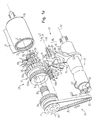
- the seat belt device comprises a drive 19 by an electric motor 31 with a drive shaft 33 and a Belt drive with a drive belt 75 and a pulley 77 is formed.
- the drive belt 75 is preferably designed as a toothed belt.
- a belt retractor 15 is optionally in a unwinding direction 1 or a winding direction 2 driven to a seat belt 11 either in a comfort mode or in to wind up in a penalty mode.
- the drive 19 is a component of the transmission 23, as the hub of the pulley 77 as the sun gear 35 of the planetary gear is trained.
- the pulley 77 can also be used as a drive pulley or drive wheel.
- the axis of rotation of the reel-up 15 coincides with the central axis of rotation 59 of the Gear 23 and the drive wheel 77 together and runs parallel offset to drive axis 57 of motor 31.
- the reel 15 is designed as a ring gear of the gear 23 and over the planet gears 39 can be driven.
- a freewheel part 37 of the transmission 23 designed as a planet gear carrier coupled.
- the freewheel part 37 is over the Planet gears 39 together with the reel 15 relative to the sun gear 35 rotatable.
- the freewheel part 37 thus enables a freewheeling mode Contraption.
- the switch 27 includes a pivotable mounted shift lever 51.
- the pivot axis 55 of the shift lever 51st runs parallel to the central axis of rotation 59.
- the multi-arm shift lever 51 is by means of a return spring 47 with the drive 19 switched off in a freewheeling mode Neutral or freewheeling position held in the Shift lever 51 is out of engagement with the gear 23.
- the part of the shift lever 51 which interacts with the transmission 23 is bow-shaped and includes two lever arms, the free ends are designed as engagement sections 63a, 63b. With the engagement sections 63a, 63b, the shift lever 51 can be pivoted out of the Engage the freewheel position in axially spaced engagement areas 67a, 67b, which are formed on the outer circumference of the freewheel part 37.
- a holding area 67a over which the freewheel part 37 by means of the shift lever 51 can be prevented from rotating includes a variety of holding receptacles 65 arranged distributed in the circumferential direction, the respective radially protruding projections of the holding area 67a are limited.
- One on the side of the pulley 77 facing the Holding area 67a located coupling area 67b comprises a toothing, so that in this area the freewheel part 37 is formed as a gear is.
- One on the outer circumference of the pulley 77 axially spaced from the belt area trained engagement area 79 for the shift lever 51 comprises also a gearing.
- the engaging portions 63a, 63b of the shift lever 51 are different formed engagement areas 67a, 67b of the freewheel part 37 customized.
- a holding section 63a can be inserted into the holding receptacles 65, to hold the freewheel member 37 while having a coupling portion 63b a non-positive connection between the pulley 77 and the freewheel part 37 can be produced.
- the holding section 63a comprises a holding tooth 81
- the Coupling section 63b two rotatably mounted on the shift lever 51 and Coupling gear wheels 83 connected to one another in a rotationally fixed manner.
- the gear wheels 83 can also be used with friction wheels engagement areas of the pulley 77 designed as friction surfaces or the freewheel part 37 cooperate. It is also possible instead two separate wheels 83 a single one, e.g. cylindrical gear or Provide friction wheel, the axial length of which is dimensioned such that it bridge the axial distance between the engagement areas 79, 67b can.
- the shift lever 51 In the freewheel mode, the shift lever 51 is in the neutral position.
- the reel 15 is freely rotatable in both directions, since the freewheel part 37 of the gear 23, which roll through on the sun gear 35 Planet gears 39 is set in rotation, also rotate freely can.
- the switch 27 is actuated via an actuation unit 71, with which a starting torque of the engine 31 is transmitted to the shift lever 51 can be.
- the operating unit 71 includes one below Cam control 85 described in more detail, which rotatably on a cylindrical Outer body 91 is attached to the drive shaft 33 of the motor 31 coaxially surrounds.
- the outer body 91 acts with the drive shaft 33 or the drive shaft 33 comprehensive drive unit 53 such that the drive shaft set in rotation by switching on the motor 31 33 or drive unit 53 on the outer body 91. hereby becomes the outer body 91 in the direction of rotation of the drive shaft 33 rotated in the opposite direction. This is due to the starting torque of the engine 31 recoil torque causes the cam control to rotate 85 of the actuator 71. This by utilizing the Recoil principle movement of the cam controller 85 becomes Operation of the shift lever 51 used.
- the cam control 85 has two in different angular directions radially from a ring section 93 surrounding the outer body 91 Cam control 85 projecting cams 87, 89.
- the cams 87, 89 serve as control sections with which the shift lever 51 to different Is acted upon.
- a cam or control section 87 is an elastically deformable bending strip formed with one end in a recess of the Ring section 93 is attached and the other end to the shift lever 51 can attack, in the embodiment shown (cf. 1b) with a bent end portion on one of the shift lever 51 protruding pin 95.
- the other control section 89 is rigidly connected to the ring section 93 Cam formed, which when rotating the ring portion 93rd cooperates with a stop surface 97 of the shift lever 51.
- the size of the starting torque of the motor 31 decides whether the Shift lever 51 only by means of the bending strip 87 in one direction is pivoted or the rigid cam 89 asserts itself by the resilient bending strip 87 overridden and the shift lever 51 in the other direction is pivoted.
- the rigid cam arrives from a predeterminable size of the starting torque 89 overcoming one that cannot be overcome if the starting torque is too low Switching resistance of the switch in engagement with the stop surface 97 and is able to shift lever 51 by deforming the bending strip 87 to pivot.
- the switch position can consequently be changed by the starting behavior of the motor 31 of the switch 27 and thus the desired transmission configuration can be set by means of the switch 27, whereupon is discussed in more detail below.
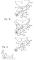
- FIG. 1c One possibility, the starting behavior of the motor 31 and thus that Influencing switching behavior is indicated schematically in FIG. 1c. It an application example is shown, in which during continuous operation following a start phase of the engine 31 in comfort mode a current of the order of magnitude 1 A and a current in the penalty mode of the order of 10 A flows.
- a start pulse is generated during the start phase whose maximum value is of the order of magnitude at 100 A and is significant from the start section of the intended for comfort mode Control signal differs.
- the continuous operating value can also be in comfort mode exceeding start pulse are generated, but its maximum value is significantly smaller than that generated in the penalty mode Start pulse.
- the start sections of the control signals are in comfort mode and in Pretensioner mode selected so that the respective starting torque corresponding recoil moments for when pivoting the Switch lever 51 each sufficiently large resistances to be overcome are.
- the recoil moment is sufficient in comfort mode not to pivot the shift lever 51 by means of the rigid cam 89, but the shift lever 51 is only by means of the bending strip 87 rotated.
- FIG. 1b shows how the shift lever in comfort mode 51 is pivoted by means of the bending strip 87 around the coupling gears 83 at the free end of a lever arm of the shift lever 51 in Engagement with the teeth 67b of the freewheel member 37 and the teeth 79 to bring the pulley 77.
- the stiffness of the bending strip 87 is selected to be large enough to deflect the return spring 47 to be able to.
- Fig. 1b shows how large enough Recoil moment of the rigid cam 89 deforming the bending strip 87 rotates the shift lever 51 in the other direction around the retaining tooth 81 of the other lever arm of the shift lever 51 in one of the holding receptacles 65 of the other engagement area 67a of the freewheel part 37.
- the return spring 47 is deflected in the other direction.
- the return spring 47 ensures that the shift lever 51 is pivoted back into the neutral position in which freely rotate the freewheel part 37 with respect to the shift lever 51 can.
- the coupling between the drive shaft 33 and the drive unit 53 on the one hand and the outer body 91 carrying the ring section 93 on the other hand is designed such that when the engine 31 is running, the shift lever 51 via the actuation unit 71 - in comfort mode via the bending strip 87 and in the penalty mode over the rigid cam 89 - in the Switch position previously set by the recoil moment is and after switching off the motor 31, the return spring 47 Switch lever 51 can pivot back into the neutral position. The freewheel mode thus recurs automatically.
- the freewheel part 37 and the sun gear 35 are through the gears 83 of the shift lever 51 synchronized, so that the Sun gear 35 and the freewheel part 37 in the same direction and with the turn at the same speed.
- the retractor 15 is driven thus by the orbital movement of the planet gears carried by the freewheel part 37 39 about the central axis of rotation 59, with a through the belt drive predetermined gear ratio, preferably is about 7: 1.
- the freewheel part 37 is by the shift lever 51 prevented from rotating so that the drive of the reel 15 by the rotation of the planet gears driven by the sun gear 35 39 takes place.
- the transmission ratio of the drive 19 of approximately 7: 1 overall between the drive shaft 33 of the motor 31 and the reel 15 a gear ratio of about 25: 1.
- the belt 11 in Pretensioner mode is wound up much faster than it is in comfort mode is handled.
Landscapes
- Engineering & Computer Science (AREA)
- Mechanical Engineering (AREA)
- Automotive Seat Belt Assembly (AREA)
- Transmission Devices (AREA)
Description
- Fig. 1a
- eine perspektivische Darstellung einer Sicherheitsgurtvorrichtung gemäß einer Ausführungsform der Erfindung,
- Fig. 1b
- Seitenansichten der Sicherheitsgurtvorrichtung von Fig. 1a, und zwar in einem Komfortmodus, einem Straffermodus und einem Freilaufmodus, und
- Fig. 1c
- eine schematische Darstellung verschiedener Ansteuersignale für einen Antrieb der erfindungsgemäßen Sicherheitsvorrichtung.
- 1
- Abwickelrichtung
- 2
- Aufwickelrichtung
- 11
- Sicherheitsgurt
- 15
- Gurtaufroller
- 19
- Antrieb
- 23
- Getriebe
- 27
- Schalter
- 31
- Elektromotor
- 33
- Antriebswelle
- 35
- Sonnenrad
- 37
- Freilaufteil
- 39
- Planetenrad
- 43
- Achse des Planetenrades
- 47
- Rückstellfeder
- 51
- Schalthebel
- 53
- Antriebseinheit
- 55
- Schwenkachse
- 57
- Antriebsachse
- 59
- zentrale Drehachse
- 63a, 63b
- Eingriffsabschnitt
- 65
- Halteaufnahme
- 67a, 67b
- Eingriffsbereich
- 71
- Betätigungseinheit
- 75
- Antriebsriemen
- 77
- Riemenscheibe, Antriebsrad
- 79
- Eingriffsbereich
- 81
- Haltezahn
- 83
- Kopplungszahnrad
- 85
- Nockensteuerung
- 87
- Steuerabschnitt, Biegestreifen
- 89
- Steuerabschnitt, starrer Nocken
- 91
- Außenkörper
- 93
- Ringabschnitt
- 95
- Stift
- 97
- Anschlagfläche
Claims (21)
- Sicherheitsgurtvorrichtung für Kraftfahrzeuge mitwobei mit dem Schalter (27) ausgehend von einem Freilaufmodus wenigstens eine Getriebekonfiguration einstellbar ist, die einem Komfortmodus mit in Abwickelrichtung (1) angetriebenem Aufroller (15) und/oder einem Straffermodus mit in Aufwickelrichtung (2) angetriebenem Aufroller (15) entspricht, dadurch gekennzeichnet, daß der Schalter (27) mittels des Antriebs (19) betätigbar ist und bei gleicher Antriebsrichtung des Antriebs (19) verschiedene Schalterstellungen einstellbar sind.einem Sicherheitsgurt (11),einem Gurtaufroller (15),einem Antrieb (19) für den Aufroller (15),einem Getriebe (23) zwischen dem Antrieb (19) und dem Aufroller (15), undeinem Schalter (27),
- Vorrichtung nach Anspruch 1,
dadurch gekennzeichnet, daß das Getriebe (23) und der Schalter (27) derart ausgebildet sind, daß bei gleicher Antriebsrichtung des Antriebs (19) mittels des Schalters (27) unterschiedliche Drehrichtungen des Aufrollers (15) und/oder unterschiedliche Übersetzungsverhältnisse des Getriebes (23) einstellbar sind. - Vorrichtung nach Anspruch 1 oder 2,
dadurch gekennzeichnet, daß mittels des Antriebs (19) auswählbare Schalterstellungen von der Größe eines Startmoments des Antriebs (19) abhängig sind. - Vorrichtung nach einem der vorhergehenden Ansprüche,
dadurch gekennzeichnet, daß mittels des Antriebs (19) auswählbare Schalterstellungen von dem Verlauf eines Ansteuersignals für einen Elektromotor (31) des Antriebs (19) abhängig sind, insbesondere von dem Verlauf eines Startimpulses des Ansteuersignals. - Vorrichtung nach einem der vorhergehenden Ansprüche,
dadurch gekennzeichnet, daß verschiedene Getriebekonfigurationen einstellbar sind, von denen eine dem Komfortmodus und eine andere dem Straffermodus entspricht. - Vorrichtung nach einem der vorhergehenden Ansprüche,
dadurch gekennzeichnet, daß mittels des Schalters (27) einstellbare Getriebekonfigurationen von der Schalterstellung abhängig sind. - Vorrichtung nach einem der vorhergehenden Ansprüche,
dadurch gekennzeichnet, daß der Schalter (27) einen schwenkbar gelagerten Schalthebel (51) umfaßt, wobei mittels des Antriebs (19) auswählbare Schalterstellungen von der Schwenkrichtung des Schalthebels (51) abhängig sind. - Vorrichtung nach einem der vorhergehenden Ansprüche,
dadurch gekennzeichnet, daß der Schalter (27) über eine Betätigungseinheit (71) ansteuerbar ist, die zur Übertragung eines Startmoments des Antriebs (19) und vorzugsweise außerdem im Anschluß an eine Startmomentübertragung zur Übertragung einer bevorzugt etwa konstanten Haltekraft auf den Schalter (27) ausgebildet ist, wobei die Betätigungseinheit (71) durch ein Rückstoßmoment aufgrund des Startmoments bewegbar ist. - Vorrichtung nach einem der vorhergehenden Ansprüche,
dadurch gekennzeichnet, daß eine Betätigungseinheit (71) für den Schalter (27) wenigstens bereichsweise eine eine Antriebswelle (33) des Antriebs (19) umfassende Antriebseinheit (53) insbesondere koaxial umgibt und gegenüber der Antriebseinheit (53) verdrehbar ist. - Vorrichtung nach einem der vorhergehenden Ansprüche,
dadurch gekennzeichnet, daß eine Betätigungseinheit (71) für den Schalter (27) eine Nockensteuerung (85) umfaßt, mit welcher der Schalter (27) beaufschlagbar ist. - Vorrichtung nach einem der vorhergehenden Ansprüche,
dadurch gekennzeichnet, daß eine Betätigungseinheit (71) für den Schalter (27) wenigstens zwei insbesondere als Nocken einer Nockensteuerung (85) ausgebildete Steuerabschnitte (87, 89) aufweist, mit denen der Schalter (27) auf unterschiedliche Weise beaufschlagbar ist. - Vorrichtung nach einem der vorhergehenden Ansprüche,
dadurch gekennzeichnet, daß Steuerabschnitte (87, 89) einer Betätigungseinheit (71) zur Übertragung von entgegengesetzten Drehmomenten auf den Schalter (27) ausgebildet sind. - Vorrichtung nach einem der vorhergehenden Ansprüche,
dadurch gekennzeichnet, daß der Schalter (27) mit Steuerabschnitten (87, 89) einer Betätigungseinheit (71) an unterschiedlichen, jeweils von einer Schwenkachse (55) des Schalters (27) beabstandeten Stellen (95, 97) beaufschlagbar ist. - Vorrichtung nach einem der vorhergehenden Ansprüche,
dadurch gekennzeichnet, daß in Abhängigkeit von der Größe eines Startmoments des Antriebs (19) der Schalter (27) entweder nur durch einen Steuerabschnitt (87) oder nacheinander durch wenigstens zwei Steuerabschnitte (87, 89) einer Betätigungseinheit (71) beaufschlagbar ist. - Vorrichtung nach einem der vorhergehenden Ansprüche,
dadurch gekennzeichnet, daß ab einer vorgebbaren Größe eines Startmoments des Antriebs (19) ein den Schalter (27) zuerst beaufschlagender Steuerabschnitt (87) einer Betätigungseinheit (71) durch einen nachfolgenden Steuerabschnitt (89) der Betätigungseinheit (71) übersteuerbar ist. - Vorrichtung nach einem der vorhergehenden Ansprüche,
dadurch gekennzeichnet, daß bei gemeinsamer Beaufschlagung des Schalters (27) durch wenigstens zwei Steuerabschnitte (87, 89) einer Betätigungseinheit (71) ein Steuerabschnitt (87) einem anderen Steuerabschnitt (89) gegenüber nachgiebig ausgebildet ist. - Vorrichtung nach einem der vorhergehenden Ansprüche,
dadurch gekennzeichnet, daß ein den Schalter (27) zuerst beaufschlagender Steuerabschnitt (87) einer Betätigungseinheit (71) durch ein mit einem anderen Steuerabschnitt (89) der Betätigungseinheit (71) auf den Schalter (27) übertragbares Drehmoment elastisch verformbar ist. - Vorrichtung nach einem der vorhergehenden Ansprüche,
dadurch gekennzeichnet, daß das Getriebe (23) ein Planetengetriebe umfaßt, wobei der Aufroller (15) als ein Hohlrad des Planetengetriebes ausgebildet ist. - Vorrichtung nach einem der vorhergehenden Ansprüche,
dadurch gekennzeichnet, daß ein Sonnenrad (35) eines Planetengetriebes drehfest mit dem Antrieb (19) verbunden ist. - Vorrichtung nach einem der vorhergehenden Ansprüche,
dadurch gekennzeichnet, daß ein den Freilaufmodus ermöglichendes Freilaufteil (37) des Getriebes (23) als Planetenradträger eines Planetengetriebes ausgebildet ist und insbesondere mit den Achsen (43) von Planetenrädern (39) gekoppelt ist. - Vorrichtung nach einem der vorhergehenden Ansprüche,
dadurch gekennzeichnet, daß nach Betätigung des Schalters (27) in Abhängigkeit von der Schalterstellung ein Freilaufteil (37) des Getriebes (23) durch den Schalter (27) entweder festgehalten oder mit dem Antrieb (19) gekoppelt ist.
Applications Claiming Priority (2)
| Application Number | Priority Date | Filing Date | Title |
|---|---|---|---|
| DE10101045 | 2001-01-11 | ||
| DE10101045A DE10101045A1 (de) | 2001-01-11 | 2001-01-11 | Sicherheitsgurtvorrichtung |
Publications (3)
| Publication Number | Publication Date |
|---|---|
| EP1223090A2 EP1223090A2 (de) | 2002-07-17 |
| EP1223090A3 EP1223090A3 (de) | 2003-07-30 |
| EP1223090B1 true EP1223090B1 (de) | 2004-08-25 |
Family
ID=7670279
Family Applications (1)
| Application Number | Title | Priority Date | Filing Date |
|---|---|---|---|
| EP02090009A Expired - Lifetime EP1223090B1 (de) | 2001-01-11 | 2002-01-10 | Sicherheitsgurtvorrichtung |
Country Status (2)
| Country | Link |
|---|---|
| EP (1) | EP1223090B1 (de) |
| DE (2) | DE10101045A1 (de) |
Families Citing this family (2)
| Publication number | Priority date | Publication date | Assignee | Title |
|---|---|---|---|---|
| DE202007009198U1 (de) | 2007-06-30 | 2007-08-30 | Alfred Schellenberg Gmbh | Gurtwickler für das Gurtband o.dgl. Zugelement einer Verdunkelungsvorrichtung, insbesondere eines Rollladens o.dgl. |
| DE102020208905A1 (de) | 2020-07-16 | 2022-01-20 | Autoliv Development Ab | Gurtaufroller |
Family Cites Families (4)
| Publication number | Priority date | Publication date | Assignee | Title |
|---|---|---|---|---|
| DE1756657A1 (de) * | 1968-06-22 | 1970-04-30 | Sigmatex Ag | Gurtbandaufroller fuer Sicherheitsgurte insbesondere von Kraftfahrzeugen |
| US5297752A (en) * | 1992-09-28 | 1994-03-29 | Trw Vehicle Safety Systems Inc. | Seat belt retractor with an automatic belt tension reducer |
| DE19731689C2 (de) * | 1997-07-23 | 1999-07-29 | Hs Tech & Design | Vorrichtung zum Aufrollen eines Sicherheitsgurtbandes |
| JP2000177535A (ja) * | 1998-12-17 | 2000-06-27 | Takata Corp | シートベルトリトラクタ |
-
2001
- 2001-01-11 DE DE10101045A patent/DE10101045A1/de not_active Withdrawn
-
2002
- 2002-01-10 EP EP02090009A patent/EP1223090B1/de not_active Expired - Lifetime
- 2002-01-10 DE DE50200878T patent/DE50200878D1/de not_active Expired - Lifetime
Also Published As
| Publication number | Publication date |
|---|---|
| EP1223090A3 (de) | 2003-07-30 |
| DE50200878D1 (de) | 2004-09-30 |
| EP1223090A2 (de) | 2002-07-17 |
| DE10101045A1 (de) | 2002-07-18 |
Similar Documents
| Publication | Publication Date | Title |
|---|---|---|
| DE60129755T2 (de) | Sicherheitsgurt-Retraktor | |
| DE10038388B4 (de) | Gurtspanner | |
| EP0161296B1 (de) | Übersetzungsnabe mit freilauf, insbesondere für rollstühle | |
| DE102018219040B4 (de) | Gurtaufroller | |
| EP3326897B1 (de) | Gangschaltung für einen elektromotirschen fahrrad-zusatzantrieb | |
| AT409030B (de) | Vorrichtung zur verstellung einer nockenwelle | |
| EP3081075B2 (de) | Schneidevorrichtung | |
| EP0743221A2 (de) | Verstellmechanismus für Kraftfahrzeugsitze | |
| DE10020245C2 (de) | Gurtaufroller für einen Fahrzeugsicherheitsgurt | |
| DE10013869C2 (de) | Komfort-Aufwickeleinrichtung für einen Sicherheitsgurt mit Motorrückholung | |
| EP1223089B1 (de) | Sicherheitsgurtvorrichtung | |
| WO2001077520A1 (de) | Vorrichtung zum kuppeln mindestens eines nebenaggregats mit einem hauptaggregat | |
| EP0759861B1 (de) | Kupplung zur drehmomentübertragung von einem durch ein treibmittel betriebenen drehantrieb auf eine gurtwelle eines sicherheitsgurtaufrollers zum straffen eines sicherheitsgurtes | |
| WO1991005692A1 (de) | Elektromotorische servolenkung | |
| EP1223090B1 (de) | Sicherheitsgurtvorrichtung | |
| EP0625449B2 (de) | Sicherheitsgurtaufrollautomat | |
| DE102020208905A1 (de) | Gurtaufroller | |
| EP1223088B1 (de) | Sicherheitsgurtvorrichtung | |
| EP0638468B1 (de) | Kupplung zum Übertragen der auf ein Zugseil wirkenden Rückstrafferbewegung auf eine Gurtbandspule eines Sicherheitsgurtaufrollautomaten | |
| DE19518052C1 (de) | Mehrgang-Antriebsnabe für Fahrräder | |
| EP0856443A1 (de) | Gurtaufroller | |
| DE10117682A1 (de) | Kraftbegrenzung in einer Aufrollvorrichtung für ein Sicherheitsgurtsystem | |
| EP0568820B1 (de) | Gurtaufroller mit Zugentlastung für Sicherheitsgurt-Rückhaltesysteme in Fahrzeugen | |
| WO1995026475A1 (de) | Muskelkraftbetätigte antriebsvorrichtung | |
| DE102021113744B4 (de) | Gurtaufroller mit einem Elektromotor |
Legal Events
| Date | Code | Title | Description |
|---|---|---|---|
| PUAI | Public reference made under article 153(3) epc to a published international application that has entered the european phase |
Free format text: ORIGINAL CODE: 0009012 |
|
| AK | Designated contracting states |
Kind code of ref document: A2 Designated state(s): AT BE CH CY DE DK ES FI FR GB GR IE IT LI LU MC NL PT SE TR |
|
| AX | Request for extension of the european patent |
Free format text: AL;LT;LV;MK;RO;SI |
|
| PUAL | Search report despatched |
Free format text: ORIGINAL CODE: 0009013 |
|
| AK | Designated contracting states |
Designated state(s): AT BE CH CY DE DK ES FI FR GB GR IE IT LI LU MC NL PT SE TR |
|
| AX | Request for extension of the european patent |
Extension state: AL LT LV MK RO SI |
|
| 17P | Request for examination filed |
Effective date: 20030929 |
|
| GRAP | Despatch of communication of intention to grant a patent |
Free format text: ORIGINAL CODE: EPIDOSNIGR1 |
|
| AKX | Designation fees paid |
Designated state(s): DE FR GB SE |
|
| GRAS | Grant fee paid |
Free format text: ORIGINAL CODE: EPIDOSNIGR3 |
|
| GRAA | (expected) grant |
Free format text: ORIGINAL CODE: 0009210 |
|
| AK | Designated contracting states |
Kind code of ref document: B1 Designated state(s): DE FR GB SE |
|
| REG | Reference to a national code |
Ref country code: GB Ref legal event code: FG4D Free format text: NOT ENGLISH |
|
| REG | Reference to a national code |
Ref country code: IE Ref legal event code: FG4D Free format text: GERMAN |
|
| REF | Corresponds to: |
Ref document number: 50200878 Country of ref document: DE Date of ref document: 20040930 Kind code of ref document: P |
|
| REG | Reference to a national code |
Ref country code: SE Ref legal event code: TRGR |
|
| GBT | Gb: translation of ep patent filed (gb section 77(6)(a)/1977) |
Effective date: 20050114 |
|
| REG | Reference to a national code |
Ref country code: IE Ref legal event code: FD4D |
|
| PLBE | No opposition filed within time limit |
Free format text: ORIGINAL CODE: 0009261 |
|
| STAA | Information on the status of an ep patent application or granted ep patent |
Free format text: STATUS: NO OPPOSITION FILED WITHIN TIME LIMIT |
|
| ET | Fr: translation filed | ||
| 26N | No opposition filed |
Effective date: 20050526 |
|
| PGFP | Annual fee paid to national office [announced via postgrant information from national office to epo] |
Ref country code: GB Payment date: 20090107 Year of fee payment: 8 |
|
| PGFP | Annual fee paid to national office [announced via postgrant information from national office to epo] |
Ref country code: SE Payment date: 20090108 Year of fee payment: 8 |
|
| GBPC | Gb: european patent ceased through non-payment of renewal fee |
Effective date: 20100110 |
|
| EUG | Se: european patent has lapsed | ||
| PG25 | Lapsed in a contracting state [announced via postgrant information from national office to epo] |
Ref country code: GB Free format text: LAPSE BECAUSE OF NON-PAYMENT OF DUE FEES Effective date: 20100110 |
|
| REG | Reference to a national code |
Ref country code: DE Ref legal event code: R082 Ref document number: 50200878 Country of ref document: DE Representative=s name: MAIKOWSKI & NINNEMANN PATENTANWAELTE, DE |
|
| PG25 | Lapsed in a contracting state [announced via postgrant information from national office to epo] |
Ref country code: SE Free format text: LAPSE BECAUSE OF NON-PAYMENT OF DUE FEES Effective date: 20100111 |
|
| REG | Reference to a national code |
Ref country code: DE Ref legal event code: R081 Ref document number: 50200878 Country of ref document: DE Owner name: TAKATA AKTIENGESELLSCHAFT, DE Free format text: FORMER OWNER: TAKATA-PETRI AG, 63743 ASCHAFFENBURG, DE Effective date: 20120904 Ref country code: DE Ref legal event code: R082 Ref document number: 50200878 Country of ref document: DE Representative=s name: MAIKOWSKI & NINNEMANN PATENTANWAELTE, DE Effective date: 20120904 Ref country code: DE Ref legal event code: R082 Ref document number: 50200878 Country of ref document: DE Representative=s name: MAIKOWSKI & NINNEMANN PATENTANWAELTE PARTNERSC, DE Effective date: 20120904 |
|
| REG | Reference to a national code |
Ref country code: FR Ref legal event code: PLFP Year of fee payment: 14 |
|
| PGFP | Annual fee paid to national office [announced via postgrant information from national office to epo] |
Ref country code: DE Payment date: 20150106 Year of fee payment: 14 |
|
| PGFP | Annual fee paid to national office [announced via postgrant information from national office to epo] |
Ref country code: FR Payment date: 20150108 Year of fee payment: 14 |
|
| REG | Reference to a national code |
Ref country code: DE Ref legal event code: R119 Ref document number: 50200878 Country of ref document: DE |
|
| REG | Reference to a national code |
Ref country code: FR Ref legal event code: ST Effective date: 20160930 |
|
| PG25 | Lapsed in a contracting state [announced via postgrant information from national office to epo] |
Ref country code: DE Free format text: LAPSE BECAUSE OF NON-PAYMENT OF DUE FEES Effective date: 20160802 |
|
| PG25 | Lapsed in a contracting state [announced via postgrant information from national office to epo] |
Ref country code: FR Free format text: LAPSE BECAUSE OF NON-PAYMENT OF DUE FEES Effective date: 20160201 |