EP1223062A1 - Verschwenkbarer Ausströmer für Fahrzeugbelüftung - Google Patents
Verschwenkbarer Ausströmer für Fahrzeugbelüftung Download PDFInfo
- Publication number
- EP1223062A1 EP1223062A1 EP02000657A EP02000657A EP1223062A1 EP 1223062 A1 EP1223062 A1 EP 1223062A1 EP 02000657 A EP02000657 A EP 02000657A EP 02000657 A EP02000657 A EP 02000657A EP 1223062 A1 EP1223062 A1 EP 1223062A1
- Authority
- EP
- European Patent Office
- Prior art keywords
- butterfly valve
- air vent
- housing
- carrier
- control element
- Prior art date
- Legal status (The legal status is an assumption and is not a legal conclusion. Google has not performed a legal analysis and makes no representation as to the accuracy of the status listed.)
- Granted
Links
Images



Classifications
-
- B—PERFORMING OPERATIONS; TRANSPORTING
- B60—VEHICLES IN GENERAL
- B60H—ARRANGEMENTS OF HEATING, COOLING, VENTILATING OR OTHER AIR-TREATING DEVICES SPECIALLY ADAPTED FOR PASSENGER OR GOODS SPACES OF VEHICLES
- B60H1/00—Heating, cooling or ventilating devices
- B60H1/34—Nozzles; Air-diffusers
-
- B—PERFORMING OPERATIONS; TRANSPORTING
- B60—VEHICLES IN GENERAL
- B60H—ARRANGEMENTS OF HEATING, COOLING, VENTILATING OR OTHER AIR-TREATING DEVICES SPECIALLY ADAPTED FOR PASSENGER OR GOODS SPACES OF VEHICLES
- B60H1/00—Heating, cooling or ventilating devices
- B60H1/34—Nozzles; Air-diffusers
- B60H2001/3471—Details of actuators
- B60H2001/3478—Details of actuators acting on additional damper doors
Definitions
- the invention relates to a vent for vehicle ventilation.
- Such air vents are in a wide variety of configurations known. They generally serve both volume and volume Direction of an air flow that a vehicle interior Air conditioning is supplied in the desired manner. Common components are a butterfly valve, by means of which the volume can be adjusted, as well as several slats, by means of where the direction of the air flow can be determined.
- the object of the invention is therefore to provide a vent create the slats are not visible when the Air vent is not required.
- the invention provides a vent for the Vehicle ventilation in front, with a housing that with an opening is provided, a butterfly valve and a plate carrier that with an outflow opening, a cladding surface and an operating element is provided, which is attached to the side of the outflow opening, the plate carrier is mounted in the housing so that it between an open position in which the outflow opening and the Control element in the opening of the housing, and one closed position is pivotable in which the cladding surface lies in the opening of the housing.
- the vent according to the invention can be brought into a state in which only the most The cladding surface of the panel carrier is visible. If those is carried out in the same way as that surrounding the outflow Dashboard, there is an attractive visual appearance, where only the gap between the cladding surface of the Air vent and the surrounding dashboard is visible.
- the butterfly valve is pivotally attached to the housing is, the control element interacts with the butterfly valve and a detachable coupling between the control element and the butterfly valve is provided by means of which the connection between the control element and the butterfly valve can be released when the plate carrier in the closed position is brought.
- the Coupling formed by an adjustment lever that with the butterfly valve is connected and has a slot open on one side, and by a pin that is attached to the control element and in the Slot can intervene.
- the releasability of this coupling is thereby given that the pin can emerge from the slot when the Disc carrier is pivoted into the closed position. If then the plate carrier back into the open position is brought, the pen is automatically back into the slot introduced and the connection from the control element to the butterfly valve is restored.
- a dashboard 10 in which a Air vent is provided for vehicle ventilation.
- a housing 14 In the dashboard there is an opening 12 (see FIG. 2) which leads to a housing 14 heard.
- a disk carrier 16 is pivotable in the housing 14 stored, which is provided with an outflow opening and at which pivotable slats 18 are attached.
- the slats 18 can in are known to be manually adjusted so that the Direction of flow of an air jet flowing out in the desired way can be set.
- Control element 20 attached that here is designed as a handwheel.
- the Handwheel is on its facing away from the dashboard 10 and thus not visible side provided with an extension 22 on which a Pin 24 is attached (see Figure 4).
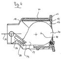
- FIG. 4 there is a butterfly valve on the housing 14 26 pivotally mounted so that it between an open, in Figure 4 shown position and a closed position is pivotable, which is shown in Figure 6.
- the closed Position the air inlet to the housing 14 is closed.
- Firm with the Butterfly valve 26 is an adjusting lever 28 connected to a Slot 30 is provided.
- the slot is designed so that it with the pin 24 on the control element 20 can cooperate. This makes possible by rotating the control element 20 about its axis of rotation 32, the Butterfly valve 26 from its open position shown in Figure 4 to put it in a closed position.
- the control element in Turned clockwise so that the pin 24 moves up and thereby bringing the butterfly valve 26 into the closed position.
- the plate carrier can be between in any way the open and closed positions are pivoted, for example by hand, by a spring mechanism or by a motor drive.
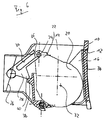
- FIGS. 5 and 6 show the movement of the disk carrier 16 and the butterfly valve 26 at the transition from the open position to see the slat carrier in the closed position. If the Disc carrier from the open position to the closed Position is pivoted, the position of the control element 20th constant relative to the disk carrier. In the embodiment shown So the control element 20 remains in the position that the fully open butterfly valve 26 with the disk carrier open equivalent. By pivoting the disk carrier 16 and the the control element 20 attached to it becomes the butterfly valve 26 automatically into the closed position shown in Figure 6 brought, in which it closes in the air inlet to the housing 14. This is particularly advantageous since there are no special requirements the tightness between the cladding surface 34 and the Dashboard 10 must be put. If the disk carrier 16 is in its closed position shown in FIG.
- the pin 24 on the extension 22 of the control element 20 has the slot 30 leave the adjusting lever 28.
- a Friction brake for the control element 20 may be provided prevents the control element 20 from unintentionally relative to Disc carrier 16 adjusted.
- Disc carrier 16 As shown in Figure 6, is on Housing 16 provided a nose 38 on a nose 40 on Swivel lever 28 attacks and the butterfly valve reliably in their holds closed position.
- a particular advantage of the adjustment lever 28 and the pin 24 detachable coupling formed between the control element and the Butterfly valve is that independent of each Position of the butterfly valve resets the same position after the slat carrier from its open to its closed Position and pivoted back into its open position has been.
- the butterfly valve in their brought closed position. Once this position is reached The pin 24 leaves the slot 30 so that the coupling between the Control element and the butterfly valve is lifted. In the Return movement, this clutch is restored, and the The butterfly valve is turned when the disk carrier is pivoted further brought back to its open position in the position it previously took.
- FIGS. 7 and 8 This is shown in FIGS. 7 and 8 in the event that the butterfly valve is in the closed position when the plate carrier is in the open position.
- the pin 24 is already at the open end of the slot 30. If the disk carrier 16 now in the in Figure 8 shown position is pivoted, in which the opening 12 of the Cladding surface 34 is closed, the pin 24 leaves immediately the slot 30 and is together with the disk carrier 16 in one Position pivoted in which he compared to that in Figure 6 shown situation is comparatively far from the slot 30. When the disk carrier 16 again in its open position is pivoted back, the pin 24 is again in the slot 30 inserted so that the coupling between control element 20 and Butterfly valve 26 is restored.
Landscapes
- Physics & Mathematics (AREA)
- Thermal Sciences (AREA)
- Engineering & Computer Science (AREA)
- Mechanical Engineering (AREA)
- Lift Valve (AREA)
- Air-Flow Control Members (AREA)
Abstract
Description
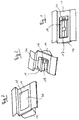
- Figur 1 in einer perspektivischen Ansicht einen Ausströmer mit Lamellenträger in einer geöffneten Stellung;
- Figur 2 in einer perspektivischen, abgeschnittenen Ansicht den Ausströmer von Figur 1 in einer Zwischenstellung;
- Figur 3 in einer perspektivischen Ansicht den Ausströmer von Figur 1 mit dem Lamellenträger in der geschlossenen Stellung;
- Figur 4 einen Schnitt durch den Ausströmer von Figur 1;
- Figur 5 einen Schnitt durch den Ausströmer von Figur 2;
- Figur 6 einen Schnitt durch den Ausströmer von Figur 3;
- Figur 7 einen Schnitt entsprechend demjenigen von Figur 4, wobei sich das Bedienelement in einer anderen Stellung befindet; und
- Figur 8 einen Schnitt entsprechend demjenigen von Figur 6, wobei sich das Bedienelement in einer anderen Stellung befindet.
Claims (10)
- Ausströmer für die Fahrzeugbelüftung, mit einem Gehäuse (14), das mit einer Öffnung (12) versehen ist, einer Absperrklappe (26) und einem Lamellenträger (16), der mit einer Ausströmöffnung, einer Verkleidungsfläche (34) und einem Bedienelement (20) versehen ist, das seitlich der Ausströmöffnung angebracht ist, wobei der Lamellenträger (16) in dem Gehäuse (14) so angebracht ist, daß er zwischen einer geöffneten Stellung, in der die Ausströmöffnung und das Bedienelement in der Öffnung (12) des Gehäuses liegen, und einer geschlossenen Stellung schwenkbar ist, in der die Verkleidungsfläche (34) in der Öffnung (12) des Gehäuses liegt.
- Ausströmer nach Anspruch 1, dadurch gekennzeichnet, daß die Absperrklappe (26) schwenkbar an dem Gehäuse (14) angebracht ist und daß das Bedienelement (20) mit der Absperrklappe (26) zusammenwirkt.
- Ausströmer nach Anspruch 2, dadurch gekennzeichnet, daß zwischen dem Bedienelement (20) und der Absperrklappe (26) eine lösbare Kupplung (24, 28, 30) vorgesehen ist, mittels der die Verbindung zwischen dem Bedienelement und der Absperrklappe gelöst werden kann, wenn der Lamellenträger (16) in die geschlossene Stellung gebracht wird.
- Ausströmer nach Anspruch 3, dadurch gekennzeichnet, daß die Kupplung durch einen Verstellhebel (28) gebildet ist, der mit der Absperrklappe (26) verbunden ist und einen an einer Seite offenen Schlitz (30) aufweist, und durch einen Stift (24), der an dem Bedienelement (20) angebracht ist und in den Schlitz eingreifen kann.
- Ausströmer nach einem der vorhergehenden Ansprüche, dadurch gekennzeichnet, daß ein Anschlag vorgesehen ist, der die Absperrklappe in einer geschlossenen Stellung halten kann.
- Ausströmer nach Anspruch 5, dadurch gekennzeichnet, daß der Anschlag durch eine Federlasche gebildet ist, die mit einem Vorsprung an der Absperrklappe zusammenwirken kann.
- Ausströmer nach einem der vorhergehenden Ansprüche, dadurch gekennzeichnet, daß eine Reibungsbremse für das Bedienelement vorgesehen ist.
- Ausströmer nach einem der vorhergehenden Ansprüche, dadurch gekennzeichnet, daß mindestens eine Lamelle (18) vorgesehen ist, die schwenkbar an dem Lamellenträger (16) in der Ausströmöffnung angebracht ist.
- Ausströmer nach einem der vorhergehenden Ansprüche, dadurch gekennzeichnet, daß die Absperrklappe (26) geschlosssen ist, wenn sich der Lamellenträger (16) in der geschlossenen Stellung befindet.
- Ausströmer nach einem der vorhergehenden Ansprüche, dadurch gekennzeichnet, daß sich die Absperrklappe (26), nachdem der Lamellenträger (16) aus der geöffneten Stellung in die geschlossene Stellung und wieder zurück in die geöffnete Stellung gebracht wurde, in derselben Stellung befindet wie vor dem Schließen des Lamellenträgers.
Applications Claiming Priority (2)
| Application Number | Priority Date | Filing Date | Title |
|---|---|---|---|
| DE20100649U | 2001-01-15 | ||
| DE20100649 | 2001-01-15 |
Publications (2)
| Publication Number | Publication Date |
|---|---|
| EP1223062A1 true EP1223062A1 (de) | 2002-07-17 |
| EP1223062B1 EP1223062B1 (de) | 2003-12-10 |
Family
ID=7951610
Family Applications (1)
| Application Number | Title | Priority Date | Filing Date |
|---|---|---|---|
| EP02000657A Expired - Lifetime EP1223062B1 (de) | 2001-01-15 | 2002-01-10 | Verschwenkbarer Ausströmer für Fahrzeugbelüftung |
Country Status (2)
| Country | Link |
|---|---|
| EP (1) | EP1223062B1 (de) |
| DE (1) | DE50200124D1 (de) |
Cited By (1)
| Publication number | Priority date | Publication date | Assignee | Title |
|---|---|---|---|---|
| EP3279019A3 (de) * | 2016-08-04 | 2018-02-21 | Dr. Ing. h.c. F. Porsche AG | Luftausströmer-verstellanordnung |
Citations (3)
| Publication number | Priority date | Publication date | Assignee | Title |
|---|---|---|---|---|
| DE1655956A1 (de) * | 1968-03-02 | 1971-10-14 | Audi Nsu Auto Union Ag | Belueftungsgeraet mit einer schwenkbaren Luftregulierklappe |
| DE19615223A1 (de) * | 1995-04-29 | 1996-10-31 | Volkswagen Ag | Luftströmungsbeeinflussungseinrichtung |
| DE19748998C1 (de) * | 1997-11-06 | 1998-10-29 | Daimler Benz Ag | Düse zum Belüften eines Fahrzeuginnenraums |
-
2002
- 2002-01-10 DE DE50200124T patent/DE50200124D1/de not_active Expired - Lifetime
- 2002-01-10 EP EP02000657A patent/EP1223062B1/de not_active Expired - Lifetime
Patent Citations (3)
| Publication number | Priority date | Publication date | Assignee | Title |
|---|---|---|---|---|
| DE1655956A1 (de) * | 1968-03-02 | 1971-10-14 | Audi Nsu Auto Union Ag | Belueftungsgeraet mit einer schwenkbaren Luftregulierklappe |
| DE19615223A1 (de) * | 1995-04-29 | 1996-10-31 | Volkswagen Ag | Luftströmungsbeeinflussungseinrichtung |
| DE19748998C1 (de) * | 1997-11-06 | 1998-10-29 | Daimler Benz Ag | Düse zum Belüften eines Fahrzeuginnenraums |
Cited By (2)
| Publication number | Priority date | Publication date | Assignee | Title |
|---|---|---|---|---|
| EP3279019A3 (de) * | 2016-08-04 | 2018-02-21 | Dr. Ing. h.c. F. Porsche AG | Luftausströmer-verstellanordnung |
| US10639967B2 (en) | 2016-08-04 | 2020-05-05 | Dr. Ing. H.C. F. Porsche Aktiengesellschaft | Air-outlet adjusting assembly |
Also Published As
| Publication number | Publication date |
|---|---|
| EP1223062B1 (de) | 2003-12-10 |
| DE50200124D1 (de) | 2004-01-22 |
Similar Documents
| Publication | Publication Date | Title |
|---|---|---|
| DE19924493C1 (de) | Düse zum Belüften eines Fahrzeuginnenraums | |
| DE102013101887B4 (de) | Einknopfbedienung für einen Luftausströmer | |
| DE19843364C1 (de) | Belüftungselement | |
| EP3530506A1 (de) | Luftausströmer | |
| EP2243647B1 (de) | Luftdüse zur Verwendung in Kraftfahrzeugen | |
| DE3908612C2 (de) | ||
| EP0970330B1 (de) | Stufenventil, insbesondere kabinenabluftventil in einem fluggerät, und verfahren zur regulierung des kabinendrucks | |
| EP3321113A1 (de) | Luftausströmer | |
| DE69909976T2 (de) | Helm für Motorradfahrer und dergleichen mit Belüftungseinrichtung | |
| DE112020006033T5 (de) | Schmale belüftungsvorrichtung für fahrzeuge | |
| DE102005012538B4 (de) | Luftdüse | |
| DE102015108394A1 (de) | Luftausströmer für ein Kraftfahrzeug | |
| DE102015206841A1 (de) | Luftausströmer für eine Heizungs- und Belüftungs- oder Klimaanlage eines Kraftfahrzeugs | |
| DE3509537C2 (de) | ||
| EP1138534B1 (de) | Luftströmungsbeeinflussungseinrichtung | |
| DE202005012570U1 (de) | Luftdüse | |
| DE10135330B4 (de) | Antriebseinrichtung für Klappen zur Steuerung der Durchströmung der Luftleitkanäle einer Kraftfahrzeug-Heizungs- oder Klimaanlage | |
| EP3921195A1 (de) | Bedieneinrichtung für ein verschwenkbar gelagertes luftleitelement | |
| DE102012105686B4 (de) | Positionierungsvorrichtung einer Mitnehmerplatte für ein Fahrzeugklimatisierungssystem | |
| EP1223062B1 (de) | Verschwenkbarer Ausströmer für Fahrzeugbelüftung | |
| DE202004000736U1 (de) | Schwenkmechanismus für Rasensprenger | |
| DE102005055700B3 (de) | Ausströmdüse für den Fahrgastraum eines Kraftfahrzeuges | |
| DE10061060B4 (de) | Luftströmungsbeeinflussungseinrichtung, insbesondere zur Verwendung in der Instrumententafel von Fahrzeugen | |
| DE102019100992B4 (de) | Luftablenkeinrichtung für einen Luftausströmer und Luftausströmer | |
| DE10109970A1 (de) | Verschwenkbarer Ausströmer für Fahrzeugbelüftung |
Legal Events
| Date | Code | Title | Description |
|---|---|---|---|
| PUAI | Public reference made under article 153(3) epc to a published international application that has entered the european phase |
Free format text: ORIGINAL CODE: 0009012 |
|
| AK | Designated contracting states |
Kind code of ref document: A1 Designated state(s): AT BE CH CY DE DK ES FI FR GB GR IE IT LI LU MC NL PT SE TR |
|
| AX | Request for extension of the european patent |
Free format text: AL;LT;LV;MK;RO;SI |
|
| 17P | Request for examination filed |
Effective date: 20030117 |
|
| GRAH | Despatch of communication of intention to grant a patent |
Free format text: ORIGINAL CODE: EPIDOS IGRA |
|
| AKX | Designation fees paid |
Designated state(s): DE ES FR GB IT |
|
| GRAS | Grant fee paid |
Free format text: ORIGINAL CODE: EPIDOSNIGR3 |
|
| GRAA | (expected) grant |
Free format text: ORIGINAL CODE: 0009210 |
|
| AK | Designated contracting states |
Kind code of ref document: B1 Designated state(s): DE ES FR GB IT |
|
| PG25 | Lapsed in a contracting state [announced via postgrant information from national office to epo] |
Ref country code: IT Free format text: LAPSE BECAUSE OF FAILURE TO SUBMIT A TRANSLATION OF THE DESCRIPTION OR TO PAY THE FEE WITHIN THE PRESCRIBED TIME-LIMIT;WARNING: LAPSES OF ITALIAN PATENTS WITH EFFECTIVE DATE BEFORE 2007 MAY HAVE OCCURRED AT ANY TIME BEFORE 2007. THE CORRECT EFFECTIVE DATE MAY BE DIFFERENT FROM THE ONE RECORDED. Effective date: 20031210 Ref country code: GB Free format text: LAPSE BECAUSE OF FAILURE TO SUBMIT A TRANSLATION OF THE DESCRIPTION OR TO PAY THE FEE WITHIN THE PRESCRIBED TIME-LIMIT Effective date: 20031210 |
|
| REG | Reference to a national code |
Ref country code: GB Ref legal event code: FG4D Free format text: NOT ENGLISH |
|
| REG | Reference to a national code |
Ref country code: IE Ref legal event code: FG4D Free format text: GERMAN |
|
| REF | Corresponds to: |
Ref document number: 50200124 Country of ref document: DE Date of ref document: 20040122 Kind code of ref document: P |
|
| PG25 | Lapsed in a contracting state [announced via postgrant information from national office to epo] |
Ref country code: ES Free format text: LAPSE BECAUSE OF FAILURE TO SUBMIT A TRANSLATION OF THE DESCRIPTION OR TO PAY THE FEE WITHIN THE PRESCRIBED TIME-LIMIT Effective date: 20040321 |
|
| GBV | Gb: ep patent (uk) treated as always having been void in accordance with gb section 77(7)/1977 [no translation filed] |
Effective date: 20031210 |
|
| REG | Reference to a national code |
Ref country code: IE Ref legal event code: FD4D |
|
| ET | Fr: translation filed | ||
| PLBE | No opposition filed within time limit |
Free format text: ORIGINAL CODE: 0009261 |
|
| STAA | Information on the status of an ep patent application or granted ep patent |
Free format text: STATUS: NO OPPOSITION FILED WITHIN TIME LIMIT |
|
| 26N | No opposition filed |
Effective date: 20040913 |
|
| REG | Reference to a national code |
Ref country code: FR Ref legal event code: ST Effective date: 20060929 |
|
| REG | Reference to a national code |
Ref country code: FR Ref legal event code: D3 |
|
| REG | Reference to a national code |
Ref country code: FR Ref legal event code: PLFP Year of fee payment: 15 |
|
| PGFP | Annual fee paid to national office [announced via postgrant information from national office to epo] |
Ref country code: DE Payment date: 20160131 Year of fee payment: 15 |
|
| PGFP | Annual fee paid to national office [announced via postgrant information from national office to epo] |
Ref country code: FR Payment date: 20160129 Year of fee payment: 15 |
|
| REG | Reference to a national code |
Ref country code: DE Ref legal event code: R119 Ref document number: 50200124 Country of ref document: DE |
|
| REG | Reference to a national code |
Ref country code: FR Ref legal event code: ST Effective date: 20170929 |
|
| PG25 | Lapsed in a contracting state [announced via postgrant information from national office to epo] |
Ref country code: FR Free format text: LAPSE BECAUSE OF NON-PAYMENT OF DUE FEES Effective date: 20170131 |
|
| PG25 | Lapsed in a contracting state [announced via postgrant information from national office to epo] |
Ref country code: DE Free format text: LAPSE BECAUSE OF NON-PAYMENT OF DUE FEES Effective date: 20170801 |