EP1220183A2 - Kombiniertes System aus Gepäcketikette und Verschlusssystem - Google Patents
Kombiniertes System aus Gepäcketikette und Verschlusssystem Download PDFInfo
- Publication number
- EP1220183A2 EP1220183A2 EP01305165A EP01305165A EP1220183A2 EP 1220183 A2 EP1220183 A2 EP 1220183A2 EP 01305165 A EP01305165 A EP 01305165A EP 01305165 A EP01305165 A EP 01305165A EP 1220183 A2 EP1220183 A2 EP 1220183A2
- Authority
- EP
- European Patent Office
- Prior art keywords
- housing
- locking
- luggage tag
- locking system
- slot
- Prior art date
- Legal status (The legal status is an assumption and is not a legal conclusion. Google has not performed a legal analysis and makes no representation as to the accuracy of the status listed.)
- Withdrawn
Links
Images

Classifications
-
- G—PHYSICS
- G09—EDUCATION; CRYPTOGRAPHY; DISPLAY; ADVERTISING; SEALS
- G09F—DISPLAYING; ADVERTISING; SIGNS; LABELS OR NAME-PLATES; SEALS
- G09F3/00—Labels, tag tickets, or similar identification or indication means; Seals; Postage or like stamps
- G09F3/02—Forms or constructions
- G09F3/03—Forms or constructions of security seals
- G09F3/0305—Forms or constructions of security seals characterised by the type of seal used
- G09F3/0347—Forms or constructions of security seals characterised by the type of seal used having padlock-type sealing means
- G09F3/0358—Forms or constructions of security seals characterised by the type of seal used having padlock-type sealing means using a rigid hasp lock
-
- G—PHYSICS
- G09—EDUCATION; CRYPTOGRAPHY; DISPLAY; ADVERTISING; SEALS
- G09F—DISPLAYING; ADVERTISING; SIGNS; LABELS OR NAME-PLATES; SEALS
- G09F3/00—Labels, tag tickets, or similar identification or indication means; Seals; Postage or like stamps
- G09F3/02—Forms or constructions
- G09F3/03—Forms or constructions of security seals
- G09F3/0305—Forms or constructions of security seals characterised by the type of seal used
- G09F3/0329—Forms or constructions of security seals characterised by the type of seal used having electronic sealing means
-
- G—PHYSICS
- G09—EDUCATION; CRYPTOGRAPHY; DISPLAY; ADVERTISING; SEALS
- G09F—DISPLAYING; ADVERTISING; SIGNS; LABELS OR NAME-PLATES; SEALS
- G09F3/00—Labels, tag tickets, or similar identification or indication means; Seals; Postage or like stamps
- G09F3/02—Forms or constructions
- G09F3/03—Forms or constructions of security seals
- G09F3/0305—Forms or constructions of security seals characterised by the type of seal used
- G09F3/0347—Forms or constructions of security seals characterised by the type of seal used having padlock-type sealing means
- G09F3/0352—Forms or constructions of security seals characterised by the type of seal used having padlock-type sealing means using cable lock
-
- Y—GENERAL TAGGING OF NEW TECHNOLOGICAL DEVELOPMENTS; GENERAL TAGGING OF CROSS-SECTIONAL TECHNOLOGIES SPANNING OVER SEVERAL SECTIONS OF THE IPC; TECHNICAL SUBJECTS COVERED BY FORMER USPC CROSS-REFERENCE ART COLLECTIONS [XRACs] AND DIGESTS
- Y10—TECHNICAL SUBJECTS COVERED BY FORMER USPC
- Y10T—TECHNICAL SUBJECTS COVERED BY FORMER US CLASSIFICATION
- Y10T70/00—Locks
- Y10T70/40—Portable
- Y10T70/402—Fetters
- Y10T70/409—Shackles
-
- Y—GENERAL TAGGING OF NEW TECHNOLOGICAL DEVELOPMENTS; GENERAL TAGGING OF CROSS-SECTIONAL TECHNOLOGIES SPANNING OVER SEVERAL SECTIONS OF THE IPC; TECHNICAL SUBJECTS COVERED BY FORMER USPC CROSS-REFERENCE ART COLLECTIONS [XRACs] AND DIGESTS
- Y10—TECHNICAL SUBJECTS COVERED BY FORMER USPC
- Y10T—TECHNICAL SUBJECTS COVERED BY FORMER US CLASSIFICATION
- Y10T70/00—Locks
- Y10T70/40—Portable
- Y10T70/413—Padlocks
- Y10T70/417—Combination-controlled
- Y10T70/435—Flexible shackle
-
- Y—GENERAL TAGGING OF NEW TECHNOLOGICAL DEVELOPMENTS; GENERAL TAGGING OF CROSS-SECTIONAL TECHNOLOGIES SPANNING OVER SEVERAL SECTIONS OF THE IPC; TECHNICAL SUBJECTS COVERED BY FORMER USPC CROSS-REFERENCE ART COLLECTIONS [XRACs] AND DIGESTS
- Y10—TECHNICAL SUBJECTS COVERED BY FORMER USPC
- Y10T—TECHNICAL SUBJECTS COVERED BY FORMER US CLASSIFICATION
- Y10T70/00—Locks
- Y10T70/80—Parts, attachments, accessories and adjuncts
- Y10T70/8432—For key-operated mechanism
- Y10T70/8676—Key holders
Definitions
- This invention relates to luggage or name-bearing tags and, more particularly, to luggage or name-bearing tags constructed to incorporate at least one locking system integrally associated therein.
- luggage or name-bearing tags have been developed and are widely employed by individuals to provide an immediate identification of the ownership of luggage which is being used during a trip.
- these prior art luggage tags comprise inexpensive plastic or paper components which are fastened to the handles of a suitcase using a simple connection system.
- a further problem typically found in prior art lock constructions is the presence of a single shackle or locking member.
- a generally J-shaped shackle is employed which is fixed in size and dimension.
- the shackle is capable of securely locking only specifically sized products and is incapable of being employed for products which are not able to fit within the dimensional limitations of the shackle.
- Another object of the present invention is to provide a combined luggage tag and locking system having the characteristic features described above which incorporates two separate and independent locking members integrally formed with the luggage tag.
- Another object of the present invention is to provide a combined luggage tag and locking system having the characteristic features described above which is capable of being easily employed by the user for externally identifying the ownership of the luggage while also securely locking the luggage in any desired location.
- a further object of the present invention is to provide a combined luggage tag and locking system having the characteristic features described above wherein both separate and independent locking systems operate using the same combination lock assembly, thereby providing flexibility as well as ease of construction, assembly, and use.
- Another object of the present invention is to provide a combined luggage tag and locking system having the characteristic features described above which employs a minimum of components and is quickly and easily assembled, thereby providing a luggage tag/locking system capable of being constructed at a competitive price.
- the present invention By employing the present invention, all of the difficulties and drawbacks of prior art products are virtually eliminated and an effective, easily produced, combined luggage tag and locking system is achieved.
- a single product is realized which is capable of identifying the owner of any suitcase or luggage with external indicia, while also effectively locking the suitcase or luggage to prevent any unwanted entry.
- the present invention substantially eliminates loss or dislodgement of the luggage tag from the suitcase.
- the combined luggage tag and locking system incorporates two separate and independent locking members, preferably a conventional shackle in combination with an elongated/flexible cable member or locking wire.
- the elongated flexible cable member is removably mounted at one and of the luggage tag housing or assembly, while the shackle is mounted at the opposed end.
- the combined luggage tag/locking system of the present invention incorporates an indicia receiving zone formed on a prominent, readily visible portion of the luggage tag housing.
- this zone By employing this zone, the user is able to place any desired individualized information required for identification purposes to enable the owner of the luggage to be readily apparent.
- an overlying transparent, window is employed in cooperation with the indicia receiving zone for protecting the information placed thereon.
- the present invention may be implemented in a plurality of alternate constructions and configurations.
- the preferred construction of the present invention employs an elongated slot formed at one end of the luggage tag housing with the slot being constructed for receiving and lockingly engaging and retaining both ends of the elongated flexible cable member.
- this construction also enables a user to completely remove the cable member from the luggage tag housing when use of the cable is not desired.
- the preferred embodiment of the present invention incorporates a plurality of rotatable dials mounted in the housing of the luggage tag for establishing a secret combination known only to the user.
- the rotatable dials are constructed for cooperating with a movable locking plate internally mounted within the luggage tag housing.
- the locking plate controls the locking of the shackle member and the opening and closing of the slot for engaging and disengaging the flexible cable member with the housing.
- the elongated flexible cable member may be constructed in a wide variety of alternate configurations as well as with a wide variety of alternate fastening members mounted at its opposed ends.
- one end of the flexible cable can be securely mounted to the housing to prevent removability of the cable therefrom.
- a removable cable is preferred, as discussed above, this alternate construction is clearly within the scope of the present invention.
- a combined luggage tag and locking system is achieved using a minimum number of independent components, each of which is capable of being quickly assembled into the final product.
- a construction is obtained which is capable of being manufactured at a competitive price, while providing a high-quality, highly effective combined luggage tag and locking system which eliminates unauthorized people from opening a suitcase of the user, while also identifying the suitcase and preventing the luggage tag from being dislodged, disconnected, or removed therefrom.
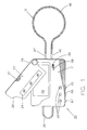
- a combined luggage tag and locking system 20 comprises a housing 21 on which indicia receiving zone 22 is formed.
- indicia receiving zone 22 comprises an enlarged area of housing 21 in order to provide high visibility for the identifying information placed therein by the user. In this way, the user or owner of the luggage to which combined luggage tag/locking system 20 is secured can be easily identified.
- combined luggage tag/locking system 20 incorporates a plate 23 which is pivotally mounted to housing 21 and incorporates a transparent window 24.
- plate 23 is constructed for being easily pivoted about pivot pin 29 relative to housing 21 in order to provide access to indicia receiving zone 22. In this way, the user is able to place the desired identifying information therein.
- plate 23 is pivoted into an overlying, covering relationship with indicia receiving zone 22, thereby protecting indicia receiving zone 22 and the information place therein from degradation from environmental conditions.
- plate 23 incorporates transparent window 24.
- transparent window 24 an observer is able to quickly and easily identify and read the information placed in indicia receiving zone 22 so as to know the owner of the luggage to which combined luggage tag/locking system 20 is affixed, without requiring arcuate pivoting movement of plate 23.
- locking means are employed, such as a raised zone or boss formed on housing 21 which cooperates with a recessed area 25 formed on plate 23.
- recessed area 25 is formed along flange 26 which extends from plate 24 and has a reduced thickness.
- housing 21 can incorporate a receiving a slot within which flange 26 is placed with recessed area 25 lockingly engaging the raised zone formed therein.
- plate 23 also incorporates a plurality of ridges 27 formed along a side edge thereof to provide a slip-free surface. In this way, the user is able to easily access ridges 27 in order to obtain rapid frictional engagement with plate 23 for causing plate 23 to pivot relative to housing 21, whenever desired.
- combination luggage tag/locking system 20 preferably comprises a plurality of indicia-bearing rotatable dials for setting and inputting a desired combination for locking and unlocking system 20.
- housing 21 comprises a plurality of apertures 28 for displaying the indicia formed on the dials.
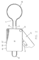
- combination luggage tag/locking system 20 of the present invention incorporates a shackle 30 and a cable member 31.
- shackle 30 comprises a conventional J-shape incorporating a short leg 33 with a terminating end 34, and a long leg 35 having a terminating end portion or section 36.
- terminating end portion 36 of long leg 35 is securely journaled in slider block 37 in a manner which enables shackle 30 to arcuately pivot or rotate about the central axis of long leg 35, while preventing terminating end portion 36 of leg 35 from being axially removed from block 37.
- any axial movement of leg 35 causes slider block 37 to move with shackle 30 relative to housing 21 of combination luggage tag/locking system 20.
- housing 21 of combination luggage tag/locking system 20 also comprises mounting blocks 38 and 39 which are formed for cooperative engagement with shackle 30.
- mounting block 38 incorporates a through hole or passageway 40 within which long leg 35 is slidingly mounted for axial movement relative thereto.
- spring member 41 is mounted about the outer surface of leg 35 sandwiched between slider block 37 and mounting block 38. In this way, any axial movement of the shackle 30 causes spring member 41 to be compressed as slider block 37 compresses spring member 41 against mounting blocks 38 as shackle 35 is slidingly moved in a direction away from housing 21. In addition, once any removal force is eliminated, spring member 41 automatically causes shackle 30 to return to its original position.
- block 39 incorporates a cavity 42 formed therein dimensioned for receiving terminating end 34 of a short leg 33.
- elongated cable or wire member 31 is lockingly engaged with housing 21.
- elongated flexible cable or wire member 31 comprises end caps 46 and 47, each of which is securely affixed to opposed ends of an elongated length of flexible, woven wire 48.
- any alternate construction which provides a secure, fully integrated, flexible, non- breakable or tamper resistant cable member can be employed with equal efficacy.
- cable member 45 is capable of being extended and lockingly engaged with a plurality of alternate products, handles, suitcases, constructions, and configurations which shackle 30 would be incapable of lockingly engaging.
- housing 21 incorporates an elongated opening 50 formed in the bottom edge thereof with plate member 51 mounted in opening 50, securely affixed therewith.
- plate member 51 preferably comprises an overall length which is greater than the length of elongated opening 50. In this way, plate member 51 is securely retained and affixed to housing 21, in a manner which renders plate member 51 non-removable from housing 21.
- plate member 51 comprises an elongated narrow slot 52 formed directly in plate member 51.
- the facing edges forming slot 52 are spaced apart a substantially equal distance throughout the overall length of slot 52.
- an enlarged zone 53 is formed at one terminating end of slot 52.
- end caps 46 and 47 of cable member 31 are constructed for being removably securely retained and lockingly mounted to housing 21 by plate member 51.
- this desired result is achieved by forming end caps 46 and 47 in a manner which enables each end cap 46 and 47 to be inserted through enlarged zone 53 and, once positioned in slot 52, end caps 46 and 47 are incapable of being removed from slot 52, except by authorized individuals.
- cable member 31 is securely affixed to housing 21 and the products through which cable member 31 has been positioned are retained in a closed and locked relationship.
- end caps 46 and 47 may comprise a plurality of alternate constructions and configurations.
- end caps 46 and 47 are constructed with a substantially cylindrical body portion 54 which is fixedly mounted to one end of flexible cable or wire member 48.
- a rod or finger portion 55 coaxially extends from body portion 54 and comprises a diameter less than the diameter of body portion 54.
- enlarged terminating end portion 56 is formed as the distal end of rod portion 55, comprising a generally rounded configuration and having a diameter substantially equal to the diameter of body portion 54.
- end caps 46 and 47 By constructing end caps 46 and 47 in this manner, the desired cooperative locking engagement and unlocking disengagement of flexible cable assembly 31 from housing 21 is achieved.
- the diameter employed for forming terminating end portion 56 is selected for enabling end portion 56 to enter enlarged zone 53.
- rod or finger portion 55 comprises a diameter which enables rod portion 55 to be freely slidable along slot 52.
- width of slot 52 is substantially less than the diameter of enlarged zone 53, terminating end portion 56 is incapable of being withdrawn through slot 52.
- cable member 31 is securely affixed and lockingly retained in plate member 51, once end caps 46 and 47 have been inserted therein and positioned along slot 52.
- combination luggage tag/locking system 20 incorporates movable abutment post 60 mounted in housing 21.
- abutment post 60 comprises a terminating end portion 61 which is positioned in direct, locking engagement with enlarged zone 53 of plate member 51 when post 60 is in its first and normal position. Whenever terminating end portion 61 is in this position, as depicted in FIGURE 3, access through enlarged zone 53 of plate member 51 is prevented. Consequently, end caps 46 and 47 are incapable of being removed from slot 52 whenever post 60 is in its first and normal position.
- abutment post 60 is movable between its first position wherein end caps 46 and 47 are lockingly retained in housing 21, and a second position wherein end caps 46 and 47 are removable from housing 21.
- terminating end portion 61 blocks access to enlarged zone 53, preventing the movement of end caps 46 and 47 through enlarged zone 53.
- abutment post 60 is moved to its second position, abutment post 60 is moved towards shackle 30 a sufficient distance to remove terminating end portion 61 from blocking enlarged zone 53, thereby enabling end caps 46 and 47 to be moved through enlarged zone 53 and removed from housing 21.
- movable abutment post 60 is constructed for cooperating controlled engagement with locking plate 62, the construction and operation of which is fully detailed below.
- locking plate 62 incorporates a receiving slot 63 within which a portion of abutment post 60 is longitudinally movable.
- spring member 64 In order to maintain abutment post 60 in a normally closed, first position, wherein abutment post 60 blocks enlarged zone 53, spring member 64 is mounted in slot 63 in direct engagement with the opposed terminating end of abutment post 60. In this way, spring member 64, which is maintained under compression, exerts its force on abutment post 60, forcing abutment post 60 into contact with plate member 61 for blocking enlarged zone 53.
- the desired, user-controlled locking and unlocking of shackle 30 and cable member 31 of combined luggage tag/locking system 20 of the present invention is provided by incorporating locking plate 62 in combination with rotatable dials 67, 68, and 69, each of which are mounted in cooperating association with one clutch ring 70, 71, or 72. Furthermore, in order to maintain clutch rings 70, 71 and 72 in frictional engagement with dials 67, 68 and 69, a spring member 73 is coaxially associated with each assembly to provide the required biasing force for maintaining each clutch ring in continuous frictional engagement with its associated dial. In this way, rotational movement of dials 67, 68 and 69 about their central axis causes clutch rings 70, 71 and 72 to rotationally move therewith.
- dials 67,68 and 69, and clutch rings 70, 71 and 72 are fully detailed below, one structural feature which is important to note is the incorporation of a slot 74 formed in each clutch ring 70, 71 and 72. As fully detailed herein, slot 74 of each clutch ring controls the locking and unlocking of combined luggage tag/locking system 20 in combination with the rotation of dials 67, 68 and 69.
- locking plate 62 comprises a generally rectangular shape, extending substantially the entire length of housing 21. In this way, locking plate 62 is capable of controlled engagement with shackle 30, cable member 31, and clutch rings 70, 71 and 72. In addition, in the preferred construction, locking plate 62 is constructed for sliding movement within housing 21.
- spring member 75 is employed, mounted between the top edge of housing 21 and a side edge of locking plate 62. With spring member 75 mounted under compression, locking plate 62 is continuously biased towards the bottom edge of housing 21, requiring a movement force to be exerted in order to cause locking plate 62 to move from its first position to its second position.
- each clutch ring 70, 71 and 72 must be placed in a precisely desired orientation or position.
- locking plate 62 incorporates fingers 78, 79 and 80 formed thereon and dimensioned for sliding engagement with slots 74 of clutch ring 70, 71 and 72.
- each slot 74 of each clutch ring 70, 71 and 72 must be positioned in juxtaposed, spaced, cooperating relationship with fingers 78, 79 and 80 before locking plate 62 is capable of being moved from its first position into its second position. If any clutch ring 70, 71 or 72 is positioned with its slot 74 arcuately spaced away from alignment with fingers 78, 79 or 80, movement of locking plate 62 is prevented.
- the required movement force for causing locking plate 62 to move from its first position to its second position is provided by the user opening either shackle 30 or cable member 31.
- this movement is attainable only when clutch rings 70, 71 and 72 are placed in the precisely required position, with each slot aligned with fingers 78, 79 and 80. As fully discussed below, this position is obtained only when the preset combination of combined luggage tag/locking system 20 has been properly entered.
- slot 74 of clutch ring 70, 71 and 72 are positioned in juxtaposed, spaced alignment with fingers 78, 79 and 80 of locking plate 62.
- locking plate 62 is able to be moved from its first position to its second position.
- either shackle 30 or abutment post 60 must be activated.
- shackle member 30 is pulled by the user in an attempt to withdraw terminating end 34 of short leg 33 from cavity 42. This movement simultaneously causes long leg 35 to move axially relative to hole 40 of block 38. Since terminating end of portion 36 of shackle 30 is securely mounted to slider block 37, axial movement of long leg 35 causes slider block 37 to move therewith.
- slider block 37 incorporates a notched area 85 with finger 86 of locking plate 62 being positioned in notched area 85. As a result, the longitudinal, sliding movement of slider block 37 causes notched area 85 to contact finger 86, which in turn causes finger 86 and its associated locking plate 62 to move therewith.
- elongated abutment post 60 is mounted in cooperative engagement with a locking plate 62 in a manner wherein the longitudinal movement of abutment post 60 is prevented by locking plate 62.
- slots 74 of clutch ring 70, 71 and 72 are aligned with fingers 78, 79 and 80 of locking plate 62, longitudinal movement of abutment post 60 is allowed with abutment post 60 causing locking plate 62 to move from its first position to its second position.
- engagement or disengagement of cable member 31 is allowed.
- abutment post 60 incorporates a readily accessible, raised slider 88 formed as an integral part of abutment post 60.
- raised slider 88 is positioned in cooperating association with slot 89 formed on the top surface of housing 21.
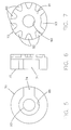
- FIGURES 5, 6 and 7, the construction of clutch ring 70 is fully shown, while FIGURES 8, 9 and 10 fully depict the construction of dial 67.
- FIGURES 5, 6 and 7, the construction of clutch ring 70 is fully shown, while FIGURES 8, 9 and 10 fully depict the construction of dial 67.
- the construction and operation of clutch rings 70, 71 and 72 and dials 67, 68 and 69 can best be understood, since each clutch ring and each dial are identical in construction in use.
- clutch ring 70 comprises a generally circular shape having a diameter which is less than the diameter of dial 67.
- a first, centrally disposed, circular hole 90 is formed in clutch ring 70 along with a second centrally disposed circular hole 89 having a diameter greater than hole 90. Both holes 89 and 90 are aligned with the central axis of clutch ring 70..
- slot 74 is formed in clutch ring 70 extending from the outer surface of clutch ring 70 to hole 89.
- clutch ring 70 comprises a dial contacting surface 91, with dial contacting surface 91 incorporating a plurality of notched zones 92 formed about the entire outer peripheral surface of clutch ring 70 and an enlarged notched zone 93.
- each notch zone 92 is substantially identical to each other and is formed in a generally U-shape.
- dial 67 comprises a generally circular shape having an overall diameter greater than the diameter of clutch ring 70 and incorporating a centrally disposed circular hole 95, coaxially aligned with the centre of dial 67.
- dial 67 incorporates a top surface 94 on which a plurality of indicia 96 are formed for ease of visibility.
- indicia 96 comprises numerals ranging from 0 through 9, with each numeral being placed adjacent each other in substantially equal spaced intervals.
- top surface 94 comprises a plurality of substantially circular shape recess zones 97 formed about hole 95 in a generally circular configuration.
- dial 67 comprises a bottom surface 98 on which a plurality of raised the bumps or bosses 99 are formed in spaced relationship with hole 95.
- raised bumps 99 can be varied or altered depending upon particular goals and objectives being sought, the general configuration of raised bumps 99 are designed for cooperative engagement with notched zones 92 and 93 of clutch ring 70.
- any desired combination can be preset for opening combined luggage tag/locking system 20 using a construction which is reasonably inexpensive to produce, while providing highly reliable results.
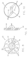
- FIGURE 11 By referring to FIGURE 11, along with the following detailed discussion, the cooperative engagement and operation of dials 67,68 and 69 along with clutch ring 70, 71 and 72 can best be understood. For ease and simplicity, one single assembly is depicted in FIGURE 9, with the following discussion having equal efficacy to each of the other assemblies.
- dial 67 is mounted on post 100 which is formed as part of housing 21.
- the diameter of post 100 is constructed for cooperating with hole 95 of dial 67 and hole 90 of clutch ring 70.
- dial 67 and clutch ring 70 are easily mounted about post 100 and freely rotatable about post 100.
- dial 67 is mounted on post 100. with surface 91 of clutch ring 70 mounted in contacting engagement with surface 98 of dial 67. The assembly of these components is completed by mounting spring member 75 on post 100 in hole 89 in biasing, contacting engagement with clutch ring 70.
- hole 89 of clutch ring 70 has a diameter larger than hole 90 to enable spring member 75 to be placed in hole 89, freely surrounding post 100 and extending therefrom.
- dials 67, 68, and 69 are rotated about the axis defined by post 100 of housing 21 until the pre-selected, combination-defining indicia 96 formed on dials 67, 68 and 69 appear through apertures 28 formed in housing 21.
- the construction detailed allows the user to individually select any desired combination for luggage tag/locking system 20 and input the desired combination to system 20 prior to use.
- the user places the indicia 96 on dials 67, 68 and 69 in the existing combination and then locks clutch rings 70, 71 and 72 by advancing slider 88 in slot 89.
- the movement of slider 88 causes fingers 78, 79 and 80 of locking plate 62 to engage slots 74 of clutch rings 70, 71 and 72, thereby preventing clutch rings 70, 71 and 72 from rotating.
- clutch rings 70, 71 and 72 are biased into frictional engagement with dials 67, 68 and 69 by spring members 73, clutch rings 70, 71 and 72 are incapable of being rotated by dials 67, 68 and 69 when the clutch rings are held in position by locking plate 62.
- the user is able to overcome the frictional engagement between clutch rings 70, 71 and 72 and dials 67, 68 and 69, enabling dial 67, 68 and 69 to be rotated relative to clutch rings 70, 71 and 72 for altering indicia 96 displayed through apertures 28 of housing 21. In this way, any desired combination can be inputted into luggage tag/locking system 20 of the present invention.
Landscapes
- Engineering & Computer Science (AREA)
- Computer Security & Cryptography (AREA)
- Physics & Mathematics (AREA)
- General Physics & Mathematics (AREA)
- Theoretical Computer Science (AREA)
- Purses, Travelling Bags, Baskets, Or Suitcases (AREA)
- Supports Or Holders For Household Use (AREA)
Applications Claiming Priority (2)
| Application Number | Priority Date | Filing Date | Title |
|---|---|---|---|
| US09/752,363 US6408660B1 (en) | 2000-12-29 | 2000-12-29 | Combined luggage tag and locking system |
| US752363 | 2000-12-29 |
Publications (2)
| Publication Number | Publication Date |
|---|---|
| EP1220183A2 true EP1220183A2 (de) | 2002-07-03 |
| EP1220183A3 EP1220183A3 (de) | 2004-07-21 |
Family
ID=25025998
Family Applications (1)
| Application Number | Title | Priority Date | Filing Date |
|---|---|---|---|
| EP01305165A Withdrawn EP1220183A3 (de) | 2000-12-29 | 2001-06-13 | Kombiniertes System aus Gepäcketikette und Verschlusssystem |
Country Status (3)
| Country | Link |
|---|---|
| US (1) | US6408660B1 (de) |
| EP (1) | EP1220183A3 (de) |
| HK (1) | HK1046055A1 (de) |
Cited By (2)
| Publication number | Priority date | Publication date | Assignee | Title |
|---|---|---|---|---|
| USD500632S1 (en) | 2002-09-23 | 2005-01-11 | Talisman Designs, Llc | Stemware adornment |
| GB2518160A (en) * | 2013-09-11 | 2015-03-18 | British Airways Plc | Identification apparatus and method |
Families Citing this family (73)
| Publication number | Priority date | Publication date | Assignee | Title |
|---|---|---|---|---|
| US6615626B2 (en) * | 2001-10-17 | 2003-09-09 | Chun Te Yu | Lock device having rotatable identification brand |
| US6860126B2 (en) * | 2002-09-04 | 2005-03-01 | Renny Tse-Haw Ling | Combination lock with dial displaying window |
| TW543692U (en) * | 2002-09-30 | 2003-07-21 | Jin Tay Ind Co Ltd | Anti-thieving device of PDA and charger |
| TW590146U (en) | 2003-05-14 | 2004-06-01 | Sinox Co Ltd | Padlock structure with hook locking and opening |
| US7424812B2 (en) | 2003-05-16 | 2008-09-16 | Stanton Concepts Inc. | Multiple function lock |
| US7434426B2 (en) | 2003-05-16 | 2008-10-14 | Stanton Concepts Inc. | Multiple function lock |
| USD497097S1 (en) | 2003-07-21 | 2004-10-12 | Illinois Tool Works Inc. | Locking or sealing device |
| USD674266S1 (en) | 2003-08-05 | 2013-01-15 | The Eastern Company | Cable shackle padlock having a sidewall aperture for a status indicator |
| US8881558B2 (en) | 2003-08-05 | 2014-11-11 | The Eastern Company | Combination and key operated locks with indicators |
| US7451561B2 (en) * | 2003-08-15 | 2008-11-18 | It's . . . In The Bag! Inc. | Identification tag |
| WO2005042881A2 (en) | 2003-10-20 | 2005-05-12 | Stanton Concepts, Inc. | Multiple function lock |
| US7518521B2 (en) * | 2003-10-29 | 2009-04-14 | Display Technologies, Inc. | Rotating anti-theft tag |
| TWM256895U (en) * | 2004-01-20 | 2005-02-11 | Fullyear Brother Entpr Co Ltd | Improved structure of padlock |
| TWM256422U (en) * | 2004-02-27 | 2005-02-01 | Fullyear Brother Entpr Co Ltd | Double locking type locking device having flexible shackle |
| US20080011027A1 (en) * | 2004-04-28 | 2008-01-17 | Yu Chun T | Padlock |
| US7712342B2 (en) | 2004-07-22 | 2010-05-11 | Stanton Concepts Inc. | Tool operated combination lock |
| US7694542B2 (en) | 2004-07-22 | 2010-04-13 | Stanton Concepts Inc. | Tool operated combination lock |
| US7047772B2 (en) * | 2004-10-13 | 2006-05-23 | Chun Te Yu | Cable lock |
| US20060179899A1 (en) * | 2004-10-13 | 2006-08-17 | Yu Chun T | Cable lock |
| TWM278736U (en) * | 2004-12-21 | 2005-10-21 | Jiun-De You | Lock device with object carrying function |
| US8353184B2 (en) | 2005-01-21 | 2013-01-15 | Sinox Company Ltd. | Tamper indicating padlock |
| USD518469S1 (en) * | 2005-04-25 | 2006-04-04 | Beverly Barad | Remote control identification system FOB |
| USD516535S1 (en) * | 2005-04-25 | 2006-03-07 | Beverly Barad | Remote actuated article identification tag |
| US20070136778A1 (en) * | 2005-12-09 | 2007-06-14 | Ari Birger | Controller and control method for media retrieval, routing and playback |
| US7269985B2 (en) * | 2005-12-20 | 2007-09-18 | The Sun Lock Company Ltd. | Magnifying lens cover for combination padlocks |
| US7453370B2 (en) * | 2005-12-28 | 2008-11-18 | Checkpoint Systems, Inc. | Merchandise tag with alarming features for securing tag to merchandise |
| US20080266111A1 (en) * | 2005-12-28 | 2008-10-30 | Checkpoint Systems, Inc. | Merchandise tag with alarming features for securing tag to merchandise |
| US20070151315A1 (en) * | 2005-12-29 | 2007-07-05 | Umbra Inc. | Combination locket and key holder |
| TWI292006B (en) | 2006-01-05 | 2008-01-01 | Sinox Co Ltd | Lock box |
| US7765840B2 (en) * | 2006-10-04 | 2010-08-03 | The Sun Lock Company Ltd. | Dual locking padlock |
| EP1914369B1 (de) * | 2006-10-16 | 2015-01-07 | The Sun Lock Company Ltd. | Vorhängeschlösser zum Halten und zur Sicherung von Reißverschlüssen |
| WO2008061287A1 (en) * | 2006-11-24 | 2008-05-29 | Origineering Pty Ltd | A padlock |
| WO2008097494A1 (en) * | 2007-02-02 | 2008-08-14 | Master Lock Company Llc | Cable lock with resettable combination |
| US20080209958A1 (en) * | 2007-03-01 | 2008-09-04 | Visotcky Robert J | Safety lock for real estate signs |
| US7631524B2 (en) * | 2007-03-01 | 2009-12-15 | Alberto Araujo | Multi-shackle lock and method of using the multi-shackle lock |
| US7685851B2 (en) * | 2007-04-13 | 2010-03-30 | The Sun Lock Company Ltd. | Security padlock having a secondary locking system |
| CN101315007B (zh) * | 2007-06-01 | 2011-12-07 | 金泰工业有限公司 | 可附设名片的锁具 |
| US7458240B1 (en) * | 2007-07-24 | 2008-12-02 | Jin Tay Industries Co., Ltd. | Combination padlock with a name card |
| US7886464B2 (en) * | 2008-01-10 | 2011-02-15 | Walt-Task, Llc | Water air land tracks baggage identification locator systems and methods |
| WO2009113990A1 (en) * | 2008-03-11 | 2009-09-17 | Global Engraving, Ltd. | Luggage tag with engraved recessed insert |
| US8839650B2 (en) * | 2008-06-25 | 2014-09-23 | Robert David Zuraski | Portable lock with modular cable |
| TW201043768A (en) * | 2009-06-06 | 2010-12-16 | Chun-Te Yu | Detachable dual lock |
| US20110203330A1 (en) * | 2010-02-25 | 2011-08-25 | Michael Grossman | Method and system for securing luggage |
| USD663780S1 (en) | 2011-04-11 | 2012-07-17 | Travel Tags, Inc. | Tag and lanyard assembly |
| US8661861B2 (en) | 2011-08-08 | 2014-03-04 | The Sun Lock Company Ltd. | Dual locking system for integrated zipper lock |
| US8898943B2 (en) * | 2012-02-09 | 2014-12-02 | Stwrap, Llc | Image display device |
| USD695976S1 (en) * | 2012-04-11 | 2013-12-17 | James C. Allen, JR. | Leash |
| USD689358S1 (en) * | 2012-04-12 | 2013-09-10 | Master Lock Company Llc | Lock |
| USD688114S1 (en) | 2012-04-12 | 2013-08-20 | Master Lock Company Llc | Lock |
| USD691458S1 (en) | 2012-04-12 | 2013-10-15 | Master Lock Company Llc | Lock |
| USD704032S1 (en) | 2012-08-28 | 2014-05-06 | Master Lock Company Llc | Lock |
| USD702102S1 (en) | 2012-08-28 | 2014-04-08 | Master Lock Company Llc | Lock |
| US9803398B2 (en) | 2015-06-30 | 2017-10-31 | The Sun Lock Company Ltd. | Combination padlock with dual locking and advanced anti-pick mechanism |
| US10047541B2 (en) | 2015-09-16 | 2018-08-14 | The Sun Lock Company, Ltd. | Dual locking system with user controllable plate |
| US10214942B2 (en) | 2016-03-30 | 2019-02-26 | The Sun Lock Company, Ltd. | Zipper padlock with a dual locking system |
| US10550608B2 (en) | 2017-12-14 | 2020-02-04 | Conair Corporation | Multiple configuration lock |
| USD935862S1 (en) | 2017-12-14 | 2021-11-16 | Conair Llc | Multiple configuration lock |
| USD892933S1 (en) * | 2018-03-07 | 2020-08-11 | Samsonite Ip Holdings S.A R.L. | Personalization tag |
| US11199025B2 (en) | 2018-12-18 | 2021-12-14 | The Sun Lock Company Limited | Combination padlock with anti-picking and decode mechanism |
| US11346127B2 (en) | 2019-06-27 | 2022-05-31 | The Sun Lock Company Limited | Hook lock with dual locking function |
| US11261622B2 (en) | 2019-08-28 | 2022-03-01 | The Sun Lock Company Limited | High security combination padlock with ease of use reset mechanism |
| USD902691S1 (en) | 2019-10-01 | 2020-11-24 | The Sun Lock Company Limited | Combination padlock |
| USD914481S1 (en) | 2019-10-15 | 2021-03-30 | The Sun Lock Company Limited | Padlock |
| US11713593B2 (en) | 2019-12-18 | 2023-08-01 | The Sun Lock Company Limited | Hook lock with dual locking function with key captive design |
| US12187492B2 (en) | 2020-07-07 | 2025-01-07 | Gary Schein | Fabric security bag |
| GB2600208B (en) | 2020-08-28 | 2023-08-23 | Sun Lock Co Ltd | Dual locking combination padlock with decode function |
| CN111924251A (zh) * | 2020-09-06 | 2020-11-13 | 覃家来 | 嵌套式立体防伪标志物 |
| US12281500B2 (en) | 2021-08-06 | 2025-04-22 | The Sun Lock Company Limited | High security combination padlock and locking bar with advanced anti-picking mechanism |
| US12037815B2 (en) * | 2021-10-26 | 2024-07-16 | Gary Schein | Cable lock |
| US12378796B1 (en) * | 2021-11-22 | 2025-08-05 | Oliver Anthony Spittle | Electronic lock with service subscription |
| USD1011865S1 (en) * | 2022-01-05 | 2024-01-23 | The Sun Lock Company Limited | Combination padlock |
| US12305429B2 (en) * | 2022-07-27 | 2025-05-20 | Gary Schein | Cable lock |
| USD1102867S1 (en) | 2023-09-06 | 2025-11-25 | The Sun Lock Company Limited | Combination padlock |
Family Cites Families (28)
| Publication number | Priority date | Publication date | Assignee | Title |
|---|---|---|---|---|
| US465450A (en) * | 1891-12-22 | William m | ||
| US2469592A (en) * | 1948-02-06 | 1949-05-10 | Celanese Corp | Locking device |
| US3719974A (en) * | 1971-03-04 | 1973-03-13 | R Abrams | Integral one-piece key ring or locking ring |
| US3908418A (en) * | 1974-02-11 | 1975-09-30 | Stoffel Seals Corp | Key holder |
| US3991594A (en) * | 1974-12-27 | 1976-11-16 | Goenner Albert O | Anti theft locking system |
| US3971458A (en) * | 1975-01-06 | 1976-07-27 | Atlantic Products Corporation | Combination identification card holder and luggage lock |
| US3961431A (en) * | 1975-09-22 | 1976-06-08 | Conversion Caddy Co. | Luggage tag |
| US4386795A (en) * | 1977-01-10 | 1983-06-07 | Precision Dynamics Corporation | Identification device with versatile imprinting means |
| US4408406A (en) * | 1981-05-29 | 1983-10-11 | Barton C D | Luggage identification tag |
| DE3410047C2 (de) * | 1983-03-23 | 1986-09-25 | S. Franzen Söhne (GmbH & Co), 5650 Solingen | Permutationsschloß mit Schlüsselgeheimnis-Neueinstellvorrichtung |
| US4616435A (en) * | 1984-04-11 | 1986-10-14 | Lafrance Corporation | Identification card holder |
| GB2227515A (en) * | 1989-01-31 | 1990-08-01 | Chern Jenn Rong | Combination padlock |
| US5311690A (en) * | 1991-09-03 | 1994-05-17 | Batten Douglas R | Identification tag |
| DE4219678A1 (de) * | 1992-06-16 | 1994-01-05 | Eduard Kuehnert | Verfahren und Anordnung zur Sicherung von Personen oder Gegenständen |
| DE69209851T2 (de) * | 1991-12-19 | 1996-09-05 | Ake Gustafson | Sicherheitsverschliessvorrichtung |
| US5236527A (en) * | 1992-01-09 | 1993-08-17 | Idesco Corp. | Method for making labelled padlocks |
| US5359867A (en) * | 1992-09-25 | 1994-11-01 | Samsonite Corporation | Combination padlock with magnifiable combinations |
| US5381617A (en) * | 1993-09-28 | 1995-01-17 | Schwartztol; Robert | Luggage tag and method |
| US5440904A (en) * | 1994-06-27 | 1995-08-15 | Su; Shun-Chang | Cable lock assembly for bicycles |
| JP3494704B2 (ja) * | 1994-08-24 | 2004-02-09 | 株式会社アルファ | 盗難防止装置 |
| US5505064A (en) * | 1995-01-25 | 1996-04-09 | Wang; Lo-Pin | Shackle lock |
| US5706679A (en) * | 1995-06-26 | 1998-01-13 | Kryptonite Corporation | Harness for securing a vehicle |
| US5868012A (en) * | 1997-10-27 | 1999-02-09 | Chun-Te; Yu | Chain lock |
| DE29917766U1 (de) * | 1999-10-08 | 2000-02-10 | Yang, Yaw-Kuen, Chang Hua | Vorhängeschloss |
| US6227016B1 (en) * | 2000-03-21 | 2001-05-08 | Chun Te Yu | Cable lock assembly |
| USD439825S1 (en) * | 2000-04-17 | 2001-04-03 | The Sun Lock Company Ltd. | Combination padlock with enlarged dials |
| US6299323B1 (en) * | 2000-10-13 | 2001-10-09 | Sun Yu | Miniature led flashlight |
| USD448273S1 (en) * | 2000-12-29 | 2001-09-25 | The Sun Lock Company Ltd. | Dual locking luggage tag |
-
2000
- 2000-12-29 US US09/752,363 patent/US6408660B1/en not_active Expired - Fee Related
-
2001
- 2001-06-13 EP EP01305165A patent/EP1220183A3/de not_active Withdrawn
-
2002
- 2002-10-08 HK HK02107342.8A patent/HK1046055A1/en unknown
Cited By (2)
| Publication number | Priority date | Publication date | Assignee | Title |
|---|---|---|---|---|
| USD500632S1 (en) | 2002-09-23 | 2005-01-11 | Talisman Designs, Llc | Stemware adornment |
| GB2518160A (en) * | 2013-09-11 | 2015-03-18 | British Airways Plc | Identification apparatus and method |
Also Published As
| Publication number | Publication date |
|---|---|
| HK1046055A1 (en) | 2002-12-20 |
| US6408660B1 (en) | 2002-06-25 |
| US20020083744A1 (en) | 2002-07-04 |
| EP1220183A3 (de) | 2004-07-21 |
Similar Documents
| Publication | Publication Date | Title |
|---|---|---|
| US6408660B1 (en) | Combined luggage tag and locking system | |
| US7562545B2 (en) | Padlock with fully integrated dual locking systems | |
| US7765840B2 (en) | Dual locking padlock | |
| US7467529B1 (en) | Lockable luggage strap assembly | |
| US7140209B2 (en) | Padlock with fully integrated dual locking systems | |
| US6474116B1 (en) | Combination lock with dual locking means | |
| US8096150B2 (en) | Padlocks for holding and securing zipper pulls | |
| US8261583B2 (en) | High security, dual-mode padlock construction | |
| US7685851B2 (en) | Security padlock having a secondary locking system | |
| EP1336705B1 (de) | Hochsicherheits-Kombinationsschloss mit Stangenverschluss | |
| JP3631248B2 (ja) | 盗難防止箱 | |
| US7117698B2 (en) | High security padlock construction | |
| US6742366B1 (en) | Locking and securing system for slot bearing products | |
| US7204106B2 (en) | Portable electronic device physical security | |
| US20100095718A1 (en) | High security, dual-mode padlock construction | |
| US6532903B2 (en) | Locking leash and collar system | |
| CA2026836A1 (en) | Safety lock | |
| CN201372636Y (zh) | 挂锁 | |
| US7269985B2 (en) | Magnifying lens cover for combination padlocks | |
| CN201141237Y (zh) | 双模式锁定挂锁 | |
| US3824816A (en) | Combination padlock | |
| JPH07217294A (ja) | 南京錠 | |
| HK1057591B (en) | High security combination padlock with locking bar |
Legal Events
| Date | Code | Title | Description |
|---|---|---|---|
| PUAI | Public reference made under article 153(3) epc to a published international application that has entered the european phase |
Free format text: ORIGINAL CODE: 0009012 |
|
| AK | Designated contracting states |
Kind code of ref document: A2 Designated state(s): AT BE CH CY DE DK ES FI FR GB GR IE IT LI LU MC NL PT SE TR |
|
| AX | Request for extension of the european patent |
Free format text: AL;LT;LV;MK;RO;SI |
|
| PUAL | Search report despatched |
Free format text: ORIGINAL CODE: 0009013 |
|
| AK | Designated contracting states |
Kind code of ref document: A3 Designated state(s): AT BE CH CY DE DK ES FI FR GB GR IE IT LI LU MC NL PT SE TR |
|
| AX | Request for extension of the european patent |
Extension state: AL LT LV MK RO SI |
|
| RIC1 | Information provided on ipc code assigned before grant |
Ipc: 7E 05B 37/14 B Ipc: 7G 09F 3/03 A |
|
| AKX | Designation fees paid | ||
| REG | Reference to a national code |
Ref country code: DE Ref legal event code: 8566 |
|
| STAA | Information on the status of an ep patent application or granted ep patent |
Free format text: STATUS: THE APPLICATION IS DEEMED TO BE WITHDRAWN |
|
| 18D | Application deemed to be withdrawn |
Effective date: 20041231 |
|
| REG | Reference to a national code |
Ref country code: HK Ref legal event code: WD Ref document number: 1046055 Country of ref document: HK |