EP1219942A1 - Druckanzeiger - Google Patents
Druckanzeiger Download PDFInfo
- Publication number
- EP1219942A1 EP1219942A1 EP01130173A EP01130173A EP1219942A1 EP 1219942 A1 EP1219942 A1 EP 1219942A1 EP 01130173 A EP01130173 A EP 01130173A EP 01130173 A EP01130173 A EP 01130173A EP 1219942 A1 EP1219942 A1 EP 1219942A1
- Authority
- EP
- European Patent Office
- Prior art keywords
- pressure
- housing
- display element
- display
- indicator according
- Prior art date
- Legal status (The legal status is an assumption and is not a legal conclusion. Google has not performed a legal analysis and makes no representation as to the accuracy of the status listed.)
- Granted
Links
- 238000013016 damping Methods 0.000 claims description 11
- 230000002093 peripheral effect Effects 0.000 claims description 8
- 238000001514 detection method Methods 0.000 claims description 3
- 239000013013 elastic material Substances 0.000 claims description 3
- 230000006835 compression Effects 0.000 claims description 2
- 238000007906 compression Methods 0.000 claims description 2
- 230000006698 induction Effects 0.000 claims description 2
- 230000001939 inductive effect Effects 0.000 claims description 2
- 230000001953 sensory effect Effects 0.000 claims description 2
- 238000007789 sealing Methods 0.000 description 5
- 238000004519 manufacturing process Methods 0.000 description 4
- 230000008878 coupling Effects 0.000 description 2
- 238000010168 coupling process Methods 0.000 description 2
- 238000005859 coupling reaction Methods 0.000 description 2
- 238000009434 installation Methods 0.000 description 2
- 238000012423 maintenance Methods 0.000 description 2
- 238000007639 printing Methods 0.000 description 2
- 238000010276 construction Methods 0.000 description 1
- 230000001419 dependent effect Effects 0.000 description 1
- 238000003912 environmental pollution Methods 0.000 description 1
- 230000003287 optical effect Effects 0.000 description 1
Images

Classifications
-
- G—PHYSICS
- G01—MEASURING; TESTING
- G01L—MEASURING FORCE, STRESS, TORQUE, WORK, MECHANICAL POWER, MECHANICAL EFFICIENCY, OR FLUID PRESSURE
- G01L7/00—Measuring the steady or quasi-steady pressure of a fluid or a fluent solid material by mechanical or fluid pressure-sensitive elements
- G01L7/16—Measuring the steady or quasi-steady pressure of a fluid or a fluent solid material by mechanical or fluid pressure-sensitive elements in the form of pistons
- G01L7/166—Measuring the steady or quasi-steady pressure of a fluid or a fluent solid material by mechanical or fluid pressure-sensitive elements in the form of pistons with mechanical transmitting or indicating means
-
- A—HUMAN NECESSITIES
- A47—FURNITURE; DOMESTIC ARTICLES OR APPLIANCES; COFFEE MILLS; SPICE MILLS; SUCTION CLEANERS IN GENERAL
- A47J—KITCHEN EQUIPMENT; COFFEE MILLS; SPICE MILLS; APPARATUS FOR MAKING BEVERAGES
- A47J27/00—Cooking-vessels
- A47J27/08—Pressure-cookers; Lids or locking devices specially adapted therefor
- A47J27/09—Safety devices
-
- G—PHYSICS
- G01—MEASURING; TESTING
- G01L—MEASURING FORCE, STRESS, TORQUE, WORK, MECHANICAL POWER, MECHANICAL EFFICIENCY, OR FLUID PRESSURE
- G01L19/00—Details of, or accessories for, apparatus for measuring steady or quasi-steady pressure of a fluent medium insofar as such details or accessories are not special to particular types of pressure gauges
- G01L19/0007—Fluidic connecting means
- G01L19/0038—Fluidic connecting means being part of the housing
-
- G—PHYSICS
- G01—MEASURING; TESTING
- G01L—MEASURING FORCE, STRESS, TORQUE, WORK, MECHANICAL POWER, MECHANICAL EFFICIENCY, OR FLUID PRESSURE
- G01L19/00—Details of, or accessories for, apparatus for measuring steady or quasi-steady pressure of a fluent medium insofar as such details or accessories are not special to particular types of pressure gauges
- G01L19/06—Means for preventing overload or deleterious influence of the measured medium on the measuring device or vice versa
- G01L19/0609—Pressure pulsation damping arrangements
-
- G—PHYSICS
- G01—MEASURING; TESTING
- G01L—MEASURING FORCE, STRESS, TORQUE, WORK, MECHANICAL POWER, MECHANICAL EFFICIENCY, OR FLUID PRESSURE
- G01L19/00—Details of, or accessories for, apparatus for measuring steady or quasi-steady pressure of a fluent medium insofar as such details or accessories are not special to particular types of pressure gauges
- G01L19/14—Housings
- G01L19/142—Multiple part housings
- G01L19/143—Two part housings
Definitions
- the present invention relates to a pressure indicator for hydraulic and / or pneumatic pressure systems, consisting of a housing with a with a Print room of the printing system connectable pressure side and an opposite Display side as well as from one in the housing between the print and display side displaceably guided display element, the display element on the pressure side can be pressurized and thus spring-loaded Rest position against spring force on the display side in a pressure display position is movable.
- Such pressure indicators as they are in principle also in so-called pressure cookers (Steam pressure pots) are provided, enable quick optical detection of the respective pressure condition.
- the pen-shaped is Display element in its spring-loaded rest position, in which it is usually on the display side with its end face is approximately flush with the housing.
- the display element against the spring force in its The housing shows a visually superior pressure display position.
- Such Pressure gauges are usually only suitable for relatively low pressures.
- the housing is made several parts screwed together, which is a relatively high Manufacturing effort and thus high costs.
- the present invention has for its object to provide a pressure indicator to create described type, by constructive and manufacturing simple and inexpensive design as a mass product for use in any Printing systems is also suitable for higher pressures.
- the display element has a Circumferential seal is sealed against the housing, the circumferential seal for Display side is held in the housing by an annular end element, the closure element preferably through a flanged housing edge is fixed, and wherein the display element in the pressure display position Lifting equipment is supported on the housing.
- the invention Pressure indicator advantageously also for continuous use, especially in hydraulic pressure systems without leakage in the area of the Pressure indicator would be feared.
- This is an important security aspect because one is still pressurized connection must not be released.
- the pressure indicator does immediately recognizable whether the line is still under pressure or is depressurized. Thereby during maintenance work accidents and environmental pollution caused by oil leaks practically excluded.
- the pressure indicator according to the invention is extremely simple due to its very simple construction inexpensive to manufacture and therefore suitable for mass production.
- the Functionally essential components are preferred within the housing kept screw-free. This is shown on the display page by the especially crimped end element reached.
- This very simple and Inexpensive installation is therefore also suitable for use at higher pressures suitable because according to the invention the display element in its pressure display position is supported on the housing by means of slings. This will make the area of Circumferential seal and the closing element holding this in the housing and also its flange fastening advantageously by pressure-related forces essential relieved.
- the housing also has the Print side on a flange, which the display element in the unpressurized Rest position rested against the spring force and thus holds in the housing.
- FIG. 2 there is a pressure indicator 1 according to the invention from a housing 2 with a pressure side 4 and an opposite Display side 6.
- the pressure side 4 is one with a pressure space 8 (cf. FIG. 1) in particular hydraulic pressure system connectable, and the display page 6 is outside in the surrounding area and thus at atmospheric pressure.
- a pen-shaped display element 10 between the print page 4 and display page 6 in a housing passage slidably guided.
- the display element 10 is on the Pressure side 4 can be acted upon with a pressure p and thus from a spring-loaded rest position (Fig. 2, left half) against return spring force F in a pressure display position projecting beyond the housing 2 on the display side 6 movable (Fig. 2, right half).
- the display element 10 is opposed by a peripheral seal 12 the housing 2 sealed.
- This peripheral seal 12 which is also a pressure-dependent version (e.g. "B + S-Stepseal") can be viewed on the display page 6 out through an annular or bush-like closure element 14 in the housing 2 held by the closure element 14 through a flanged housing edge 16 is fixed in the housing 2.
- the display element 10 in the pressure display position (see the right half again in FIG. 2)
- Lifting means 18 is supported directly on the housing 2. This will make the Fixing the end element 14 by the flanged housing edge 16 advantageously relieved of pressure-related forces by such forces be largely kept away from this area.
- the stop means 18 are on the one hand themselves radially extending ring extension 20 at the free end facing the pressure side 4 Display element 10 and on the other hand from a radial step surface 22 in Housing 2 formed.
- the peripheral seal 12 is seated - preferably together with a support ring 24 their side facing the display side 6 and the end element 14 - in one Annular chamber 26 between a radial housing surface 28 and the closure element 14.
- the closure element 14 thus delimits the annular chamber 26 to the display side 6 out.
- the closure element 14 itself sits in a housing recess 30, the preferably opposite the sealing ring chamber 26 via a step surface 32 is expanded.
- the closure member 14 is axially clamped between the Stepped surface 32 and the flanged edge of the housing 16.
- the closure element 14 is preferably approximately conical chamfered contact surface 34.
- a helical compression spring 36 is preferably used to generate the resetting spring force F provided that enclosing the display element 10 in a spring chamber 38 of the Housing 2 axially between the end ring projection 20 of the display element 10 and one, the spring chamber 38 on the pressure side 4 opposite it Circumferential seal 12 facing side step surface 40 of the housing 2 is arranged. Between this step surface 40 delimiting the spring chamber 38 and the annular chamber 26 receiving the peripheral seal 12 is in the housing 2 Guide area 42 is formed for the pin-shaped display element 10. Another The guide to the tilt-free sliding guide of the display element 10 forms the End element 14 with a corresponding central guide opening 44.
- damping means for Movement damping of the display element 10 is provided.
- damping means for Movement damping of the display element 10 is provided.
- the preferred embodiment shown is the ring extension 22 of the display element 10 piston-like in a housing extension 46 open in the direction of the pressure side 4 guided, with a passage for between the pressure side 4 and the spring chamber 38 the respective pressure medium formed such that when the display element moves 10 a flow damping takes place.
- the spring chamber 38 forms one Volume chamber for holding a specific full volume of the respective Pressure medium.
- the pressure medium passage can be through an annular gap between the Ring approach 20 of the display element 10 and the inner surface of the Housing extension 46 may be formed.
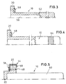
- FIG. 2 and 3 illustrates that the passage through a central blind hole 50 of the Display element 10 in combination with at least one (as shown, for example, two) radial flow opening 52 is formed.
- the or each radial Flow opening 52 in a region which in each position of the display element 10 lies in the area of the spring chamber 38.
- the passage is dimensioned in terms of its effective flow cross-section that in any case during the movements of the display element 10 Motion damping is achieved.
- the pressure medium passage can also be advantageous Damping valve means can be assigned such that in the two directions of movement of the display element 10 damping of different strengths can be achieved.
- a profile element 54 is made of a rubber-elastic material is provided, which sits on the ring shoulder 20 and with a diaphragm valve-like section 56, in particular on the pressure side 4, the or covers each axial flow opening 48.
- This will make a check valve formed, whereby in particular the movement from the pressure display position back in the rest position is dampened more than the reverse movement.
- at least one contact element 58 in the area of the stop means 18 is arranged from a rubber-elastic material. This makes it more elastic End stop for the display element 10 is formed in the pressure display position. This prevents annoying noises. 3 and 4 it is in the case of the contact element 58 around a ring which lies on the ring extension 20 and this towered over in the direction of the end stop position.
- Fig. 5 it is a corresponding section of the profile element 54.
- the display element is integral with the Ring shoulder 20 formed. 5 there is the display element 10 from an elongated, cylindrical pin element 60 and a ring extension 20 having support element 62, which has a cap-like end on the pin element 60 sits and is fastened in a suitable manner, for example non-positively and / or positively and / or cohesive.
- This embodiment has the advantage that a pin element 60 is used Needle roller bearings can be used. Such parts are extraordinary Available inexpensively, but still offer high quality for a good seal and low kinetic friction because it has a smooth, polished and hardened surface exhibit.
- the display element 10 in particular in its free, the Display side 6 facing area - a trigger element 64, for example a Induction band, for a sensory, for example inductive detection of Have pressure display position.
- a trigger element 64 for example a Induction band, for a sensory, for example inductive detection of Have pressure display position.
- the housing 2 also has one on the pressure side 4 Flanged edge 66 on, against the display element 10 in the depressurized rest position supports the spring force F and holds it in the housing 2 such that the display element 10 in the rest position on the display side 6 essentially flush with the housing 2 or ends with the end element 14.
- a line connection fitting 68 is also shown, which for Connection of the pressure indicator 1 according to the invention is used on a pressure line.
- To the connection fitting 68 has at least one, as shown e.g. two Line connections 70, 72 and a branch termination 74 for the pressure side 4 of the Housing 2 of the pressure indicator 1 according to the invention.
- the Line connection fitting 68 on a T-shaped connection housing.
- the pressure indicator 1 preferably has an external thread connection 76 on the pressure side Screwing into a corresponding internal thread 78 of the branch connection 74 the connection fitting 68.
- a sealing ring 80 is provided for sealing.
- the invention is not based on the illustrated and described Embodiments limited, but also includes all within the meaning of the invention equivalent designs. Furthermore, the invention is not yet open the combination of features defined in claim 1 limits, but can also through any other combination of certain characteristics of all overall disclosed individual features can be defined. This means that basically omitted practically every single feature of claim 1 or by at least one individual feature disclosed elsewhere in the application can be replaced. In this respect, claim 1 is only a first To understand the attempt to formulate an invention.
Landscapes
- Physics & Mathematics (AREA)
- General Physics & Mathematics (AREA)
- Engineering & Computer Science (AREA)
- Food Science & Technology (AREA)
- Measuring Fluid Pressure (AREA)
Abstract
Description
- Fig. 1
- eine teilgeschnittene Seitenansicht eines erfindungsgemäßen Druckanzeigers zusammen mit einer zum Einbau in eine Druckleitung vorgesehenen Leitungsanschlußarmatur,
- Fig. 2
- einen vergrößerten Längsschnitt des erfindungsgemäßen Druckanzeigers,
- Fig. 3
- einen verkürzten Halb- Längsschnitt des Anzeigeelementes nach Fig. 2 in weiterer Ausgestaltung,
- Fig. 4
- eine Ansicht ähnlich Fig. 3 in einer weiteren Ausgestaltungsvariante und
- Fig. 5
- noch eine weitere Variante des Anzeigeelementes in einer Darstellung ähnlich Fig. 4.
Claims (14)
- Druckanzeiger (1) für hydraulische und/oder pneumatische Drucksysteme, bestehend aus einem Gehäuse (2) mit einer mit einem Druckraum (8) des Drucksystems verbindbaren Druckseite (4) und einer entgegengesetzten Anzeigeseite (6) sowie aus einem in dem Gehäuse (2) zwischen Druck- und Anzeigeseite (4, 6) verschiebbar geführten Anzeigeelement (10), wobei das Anzeigeelement (10) auf der Druckseite (4) mit einem Druck (p) beaufschlagbar und dadurch aus einer federbedingten Ruheposition gegen Federkraft (F) auf der Anzeigeseite (6) in eine Druckanzeigeposition verschiebbar ist,
dadurch gekennzeichnet, dass das Anzeigeelement (10) über eine Umfangsdichtung (12) gegen das Gehäuse (2) abgedichtet ist, wobei die Umfangsdichtung (12) zur Anzeigeseite (6) hin durch ein ringförmiges Abschlußelement (14) im Gehäuse (2) gehalten ist, wobei das Abschlußelement (14) insbesondere durch einen umgebördelten Gehäuserand (16) fixiert ist, und wobei das Anzeigeelement (10) in der Druckanzeigeposition über Anschlagmittel (18) am Gehäuse (2) abgestützt wird. - Druckanzeiger nach Anspruch 1,
dadurch gekennzeichnet, dass die Anschlagmittel (18) einerseits von einem sich radial erstreckenden Ringansatz (20) am freien, der Druckseite (4) zugekehrten Ende des Anzeigeelementes (10) und andererseits von einer radialen Stufenfläche (22) im Gehäuse (2) gebildet sind. - Druckanzeiger nach Anspruch 1 oder 2,
dadurch gekennzeichnet, dass die Umfangsdichtung (12) - vorzugsweise gemeinsam mit einem Stützring (24) - in einer Ringkammer (26) zwischen einer radialen Gehäusefläche (28) und dem Abschlußelement (14) sitzt. - Druckanzeiger nach Anspruch 2 oder 3,
dadurch gekennzeichnet, dass zur Erzeugung der Federkraft (F) ein Druckfederelement (36) das Anzeigeelement (10) umschließend in einer Federkammer (38) des Gehäuses (2) axial zwischen dem endseitigen Ringansatz (20) des Anzeigeelement (10) und einer die Federkammer (38) auf ihrer der Druckseite (4) gegenüberliegenden, der Umfangsdichtung (12) zugekehrten Seite begrenzenden Stufenfläche (40) des Gehäuses (2) angeordnet ist. - Druckanzeiger nach einem der Ansprüche 1 bis 4,
gekennzeichnet durch Dämpfungsmittel zur Bewegungsdämpfung des Anzeigeelementes (10). - Druckanzeiger nach einem der Ansprüche 2 bis 5,
dadurch gekennzeichnet, dass der Ringansatz (20) des Anzeigeelementes (10) kolbenartig in einer in Richtung der Druckseite (4) offenen Gehäuseerweiterung (46) geführt ist, wobei zwischen der Druckseite (4) und der Federkammer (38) eine Passage für das jeweilige Druckmittel derart gebildet ist, dass bei Bewegungen des Anzeigeelementes (10) eine Strömungsdämpfung erfolgt. - Druckanzeiger nach Anspruch 6,
dadurch gekennzeichnet, dass die Druckmittel-Passage durch einen Ringspalt zwischen dem Ringansatz (20) des Anzeigeelementes (10) und der Gehäuseerweiterung (46) und/oder durch mindestens eine axiale Strömungsöffnung (48) des Ringansatzes (20) und/oder durch ein Sackloch (50) des Anzeigeelementes (10) in Kombination mit mindestens einer radialen Strömungsöffnung (52) gebildet ist. - Druckanzeiger nach Anspruch 6 oder 7,
dadurch gekennzeichnet, dass der Druckmittel-Passage Dämpfungsventilmittel derart zugeordnet sind, dass in den zwei Bewegungsrichtungen des Anzeigeelementes (10) unterschiedlich starke Dämpfungen erreicht werden. - Druckanzeiger nach einem der Ansprüche 1 bis 8,
dadurch gekennzeichnet, dass im Bereich der Anschlagmittel (18) mindestens ein Anlageelement (58) aus einem gummielastischen Material vorgesehen ist. - Druckanzeiger nach einem der Ansprüche 1 bis 9,
dadurch gekennzeichnet, dass das Anzeigeelement (10) einstückig mit dem Ringansatz (20) ausgebildet ist. - Druckanzeiger nach einem der Ansprüche 1 bis 9,
dadurch gekennzeichnet, dass das Anzeigeelement (10) zumindest zweiteilig aus einem länglichen, zylindrischen Stiftelement (60) und einem der Ringansatz (20) aufweisenden, einendig kappenartig auf dem Stiftelement (60) sitzenden Stützelement (62) besteht. - Druckanzeiger nach einem der Ansprüche 1 bis 11,
dadurch gekennzeichnet, dass das Anzeigeelement (10) - insbesondere in seinem freien, der Anzeigeseite (6) zugekehrten Bereich - ein Auslöseelement (64), z. B. ein Induktionsband, für eine sensorische, z. B. induktive Erfassung der Druckanzeigeposition aufweist. - Druckanzeiger nach einem der Ansprüche 1 bis 12,
dadurch gekennzeichnet, dass das Gehäuse (2) auf der Druckseite (4) einen Bördelrand (66) aufweist, der das Anzeigeelement (10) in der drucklosen Ruheposition gegen die Federkraft (F) abstützt. - Druckanzeiger nach einem der Ansprüche 1 bis 13,
gekennzeichnet durch eine Leitungsanschlußarmatur (68) mit mindestens einem Leitungsanschluß (70, 72)und einem Abzweiganschluß (74) für die Druckseite (4) des Gehäuses (2).
Applications Claiming Priority (2)
| Application Number | Priority Date | Filing Date | Title |
|---|---|---|---|
| DE20021823U | 2000-12-22 | ||
| DE20021823U DE20021823U1 (de) | 2000-12-22 | 2000-12-22 | Druckanzeiger für Drucksysteme |
Publications (2)
| Publication Number | Publication Date |
|---|---|
| EP1219942A1 true EP1219942A1 (de) | 2002-07-03 |
| EP1219942B1 EP1219942B1 (de) | 2004-08-11 |
Family
ID=7950511
Family Applications (1)
| Application Number | Title | Priority Date | Filing Date |
|---|---|---|---|
| EP01130173A Expired - Lifetime EP1219942B1 (de) | 2000-12-22 | 2001-12-19 | Druckanzeiger |
Country Status (3)
| Country | Link |
|---|---|
| EP (1) | EP1219942B1 (de) |
| DE (2) | DE20021823U1 (de) |
| ES (1) | ES2223722T3 (de) |
Cited By (11)
| Publication number | Priority date | Publication date | Assignee | Title |
|---|---|---|---|---|
| WO2009133721A1 (ja) * | 2008-04-30 | 2009-11-05 | 住友ゴム工業株式会社 | コンプレッサ装置 |
| CN103728092A (zh) * | 2012-10-12 | 2014-04-16 | 马格纳斯泰尔汽车技术两合公司 | 用于高压存储设备的压力表 |
| USD707332S1 (en) | 2013-03-15 | 2014-06-17 | S.P.M. Flow Control, Inc. | Seal assembly |
| USD707797S1 (en) | 2013-03-15 | 2014-06-24 | S.P.M. Flow Control, Inc. | Seal segment |
| US8870233B2 (en) | 2007-07-03 | 2014-10-28 | S.P.M. Flow Control, Inc. | Swivel joint with uniform ball bearing requirements |
| US8978695B2 (en) | 2009-04-20 | 2015-03-17 | S.P.M. Flow Control, Inc. | Flowline flapper valve |
| US8998168B2 (en) | 2009-06-03 | 2015-04-07 | S.P.M. Flow Control, Inc. | Plug valve indicator |
| US9103448B2 (en) | 2012-08-16 | 2015-08-11 | S.P.M. Flow Control, Inc. | Plug valve having preloaded seal segments |
| IT201600097477A1 (it) * | 2016-09-28 | 2018-03-28 | Dropsa Spa | Indicatore di sovra-pressione |
| EP3421960A1 (de) * | 2017-06-26 | 2019-01-02 | Jansen AG | Druckanzeiger |
| EP4439031A1 (de) * | 2023-03-28 | 2024-10-02 | Exel Industries | Anzeiger zur anzeige der überbelegung eines unter druck stehenden flüssigkeitslecks in einer entlüftungskammer eines druckflüssigkeitsgeräts |
Families Citing this family (6)
| Publication number | Priority date | Publication date | Assignee | Title |
|---|---|---|---|---|
| US9322243B2 (en) | 2012-08-17 | 2016-04-26 | S.P.M. Flow Control, Inc. | Automated relief valve control system and method |
| US9273543B2 (en) | 2012-08-17 | 2016-03-01 | S.P.M. Flow Control, Inc. | Automated relief valve control system and method |
| CA2916699A1 (en) | 2013-07-01 | 2015-01-08 | S.P.M. Flow Control, Inc. | Manifold assembly |
| CN204797561U (zh) * | 2014-11-19 | 2015-11-25 | 史利利 | 压力传感器安装结构及电压力锅 |
| WO2016205208A1 (en) | 2015-06-15 | 2016-12-22 | S.P.M. Flow Control, Inc. | Full-root-radius-threaded wing nut having increased wall thickness |
| US10677365B2 (en) | 2015-09-04 | 2020-06-09 | S.P.M. Flow Control, Inc. | Pressure relief valve assembly and methods |
Citations (5)
| Publication number | Priority date | Publication date | Assignee | Title |
|---|---|---|---|---|
| US2036391A (en) * | 1930-06-28 | 1936-04-07 | Thomas W Bradley | Relief valve for unfired pressure vessels |
| US4389962A (en) * | 1980-03-29 | 1983-06-28 | Kurt Stoll | Optical display unit for pneumatic systems |
| US5014786A (en) * | 1989-03-10 | 1991-05-14 | Nitto Kohku Co., Ltd. | Pressure checker |
| EP0927878A2 (de) * | 1997-12-30 | 1999-07-07 | HTM SPORT S.p.A. | Druckanzeige für Flaschen mit Druckgas |
| JP2000170934A (ja) * | 1998-12-10 | 2000-06-23 | Fujikura Rubber Ltd | リリーフ弁 |
-
2000
- 2000-12-22 DE DE20021823U patent/DE20021823U1/de not_active Expired - Lifetime
-
2001
- 2001-12-19 DE DE50103208T patent/DE50103208D1/de not_active Expired - Lifetime
- 2001-12-19 ES ES01130173T patent/ES2223722T3/es not_active Expired - Lifetime
- 2001-12-19 EP EP01130173A patent/EP1219942B1/de not_active Expired - Lifetime
Patent Citations (5)
| Publication number | Priority date | Publication date | Assignee | Title |
|---|---|---|---|---|
| US2036391A (en) * | 1930-06-28 | 1936-04-07 | Thomas W Bradley | Relief valve for unfired pressure vessels |
| US4389962A (en) * | 1980-03-29 | 1983-06-28 | Kurt Stoll | Optical display unit for pneumatic systems |
| US5014786A (en) * | 1989-03-10 | 1991-05-14 | Nitto Kohku Co., Ltd. | Pressure checker |
| EP0927878A2 (de) * | 1997-12-30 | 1999-07-07 | HTM SPORT S.p.A. | Druckanzeige für Flaschen mit Druckgas |
| JP2000170934A (ja) * | 1998-12-10 | 2000-06-23 | Fujikura Rubber Ltd | リリーフ弁 |
Non-Patent Citations (1)
| Title |
|---|
| PATENT ABSTRACTS OF JAPAN vol. 2000, no. 09 13 October 2000 (2000-10-13) * |
Cited By (24)
| Publication number | Priority date | Publication date | Assignee | Title |
|---|---|---|---|---|
| US8870233B2 (en) | 2007-07-03 | 2014-10-28 | S.P.M. Flow Control, Inc. | Swivel joint with uniform ball bearing requirements |
| US9964245B2 (en) | 2007-07-03 | 2018-05-08 | S.P.M. Flow Control, Inc. | Swivel joint with uniform ball bearing requirements |
| WO2009133721A1 (ja) * | 2008-04-30 | 2009-11-05 | 住友ゴム工業株式会社 | コンプレッサ装置 |
| US8562306B2 (en) | 2008-04-30 | 2013-10-22 | Sumitomo Rubber Industries, Ltd. | Compressor apparatus |
| CN102016310B (zh) * | 2008-04-30 | 2013-11-13 | 住友橡胶工业株式会社 | 压缩机设备 |
| EP2275679A4 (de) * | 2008-04-30 | 2017-04-26 | Sumitomo Rubber Industries, Ltd. | Verdichter |
| US8978695B2 (en) | 2009-04-20 | 2015-03-17 | S.P.M. Flow Control, Inc. | Flowline flapper valve |
| US8998168B2 (en) | 2009-06-03 | 2015-04-07 | S.P.M. Flow Control, Inc. | Plug valve indicator |
| US9638337B2 (en) | 2012-08-16 | 2017-05-02 | S.P.M. Flow Control, Inc. | Plug valve having preloaded seal segments |
| US9103448B2 (en) | 2012-08-16 | 2015-08-11 | S.P.M. Flow Control, Inc. | Plug valve having preloaded seal segments |
| JP2014081373A (ja) * | 2012-10-12 | 2014-05-08 | Magna Steyr Fahrzeugtechnik Ag & Co Kg | 圧力計 |
| EP2720022A1 (de) | 2012-10-12 | 2014-04-16 | Magna Steyr Fahrzeugtechnik AG & Co KG | Druckanzeiger für Hochdruckspeicheranlagen |
| CN103728092A (zh) * | 2012-10-12 | 2014-04-16 | 马格纳斯泰尔汽车技术两合公司 | 用于高压存储设备的压力表 |
| US9383183B2 (en) | 2012-10-12 | 2016-07-05 | Magna Steyr Fahrzeugtechnik Ag & Co Kg | Pressure indicator |
| CN103728092B (zh) * | 2012-10-12 | 2016-11-23 | 马格纳斯泰尔汽车技术两合公司 | 用于高压存储设备的压力表 |
| USD707332S1 (en) | 2013-03-15 | 2014-06-17 | S.P.M. Flow Control, Inc. | Seal assembly |
| USD734434S1 (en) | 2013-03-15 | 2015-07-14 | S.P.M. Flow Control, Inc. | Seal assembly |
| USD707797S1 (en) | 2013-03-15 | 2014-06-24 | S.P.M. Flow Control, Inc. | Seal segment |
| IT201600097477A1 (it) * | 2016-09-28 | 2018-03-28 | Dropsa Spa | Indicatore di sovra-pressione |
| EP3301423A1 (de) * | 2016-09-28 | 2018-04-04 | DROPSA S.p.A. | Überdruckindikator |
| US10466128B2 (en) | 2016-09-28 | 2019-11-05 | Dropsa S.P.A. | Overpressure indicator |
| EP3421960A1 (de) * | 2017-06-26 | 2019-01-02 | Jansen AG | Druckanzeiger |
| EP4439031A1 (de) * | 2023-03-28 | 2024-10-02 | Exel Industries | Anzeiger zur anzeige der überbelegung eines unter druck stehenden flüssigkeitslecks in einer entlüftungskammer eines druckflüssigkeitsgeräts |
| FR3147368A1 (fr) * | 2023-03-28 | 2024-10-04 | Exel Industries | Indicateur pour indiquer la survenance d’une fuite de fluide pressurisé dans une chambre d’évent d’un appareil à fluide pressurisé |
Also Published As
| Publication number | Publication date |
|---|---|
| DE50103208D1 (de) | 2004-09-16 |
| DE20021823U1 (de) | 2001-03-15 |
| ES2223722T3 (es) | 2005-03-01 |
| EP1219942B1 (de) | 2004-08-11 |
Similar Documents
| Publication | Publication Date | Title |
|---|---|---|
| EP1219942B1 (de) | Druckanzeiger | |
| DE2430410A1 (de) | Ventil, insbesondere kugelventil | |
| EP2017511A1 (de) | Piezoelektrisches Ventil | |
| DE2506928C3 (de) | Gebirgsschlagventil für hydraulische Grubenstempel | |
| EP2962022A2 (de) | Überströmventil | |
| EP1678434B1 (de) | Ventil, insbesondere gassicherheitsventil | |
| DE102016109129A1 (de) | Membranventil | |
| DE3929094A1 (de) | Gebirgsschlagventil mit doppelkolben | |
| EP0412997B1 (de) | Dichtungsanordnung | |
| DE3441348A1 (de) | Ventilanordnung | |
| DE9106694U1 (de) | Druckschalter | |
| DE3420890C2 (de) | ||
| DE202017001547U1 (de) | Doppelt wirkendes Überströmventil eines Arbeitszylinders und Master-Arbeitszylinder | |
| DE29709021U1 (de) | Rückschlagventil | |
| DE2500552C2 (de) | Sicherungsventil fuer rohr- bzw. schlauchbrueche | |
| DE2254263A1 (de) | Sicherheitsventil | |
| DE2256959C3 (de) | Rückschlag-Klappenventil | |
| DE10155629A1 (de) | Sitzventil | |
| WO2018210374A1 (de) | Energizer-dichtungsdesign für kupplungsnehmerzylindern | |
| EP0589863A1 (de) | Hydraulikzylinder | |
| DE2834002C2 (de) | Hydraulisch lüftbare Federdruckbremse oder -Kupplung | |
| DE2659452C2 (de) | Pressostat mit einem Sicherheitszusatzbalg | |
| DE102006042096B4 (de) | Anordnung zum Verschließen einer Hochdruckbohrung | |
| DE102008059518B4 (de) | Gasdruckfeder | |
| DE3040220C1 (de) | Umschaltventil fuer Verbundzaehler |
Legal Events
| Date | Code | Title | Description |
|---|---|---|---|
| PUAI | Public reference made under article 153(3) epc to a published international application that has entered the european phase |
Free format text: ORIGINAL CODE: 0009012 |
|
| AK | Designated contracting states |
Kind code of ref document: A1 Designated state(s): AT BE CH CY DE DK ES FI FR GB GR IE IT LI LU MC NL PT SE TR |
|
| AX | Request for extension of the european patent |
Free format text: AL;LT;LV;MK;RO;SI |
|
| 17P | Request for examination filed |
Effective date: 20021030 |
|
| RIN1 | Information on inventor provided before grant (corrected) |
Inventor name: POTT, HARALD Inventor name: HESTER, HILMAR Inventor name: LOX, EGBERT, DR. Inventor name: KREUZER, THOMAS, DR. |
|
| RIN1 | Information on inventor provided before grant (corrected) |
Inventor name: HESTER, HILMAR Inventor name: POTT, HARALD |
|
| AKX | Designation fees paid |
Designated state(s): DE |
|
| RBV | Designated contracting states (corrected) |
Designated state(s): DE ES FR GB IT |
|
| GRAP | Despatch of communication of intention to grant a patent |
Free format text: ORIGINAL CODE: EPIDOSNIGR1 |
|
| GRAS | Grant fee paid |
Free format text: ORIGINAL CODE: EPIDOSNIGR3 |
|
| GRAA | (expected) grant |
Free format text: ORIGINAL CODE: 0009210 |
|
| AK | Designated contracting states |
Kind code of ref document: B1 Designated state(s): DE ES FR GB IT |
|
| REG | Reference to a national code |
Ref country code: GB Ref legal event code: FG4D Free format text: NOT ENGLISH |
|
| GBT | Gb: translation of ep patent filed (gb section 77(6)(a)/1977) |
Effective date: 20040811 |
|
| REG | Reference to a national code |
Ref country code: IE Ref legal event code: FG4D Free format text: GERMAN |
|
| REF | Corresponds to: |
Ref document number: 50103208 Country of ref document: DE Date of ref document: 20040916 Kind code of ref document: P |
|
| ET | Fr: translation filed | ||
| REG | Reference to a national code |
Ref country code: ES Ref legal event code: FG2A Ref document number: 2223722 Country of ref document: ES Kind code of ref document: T3 |
|
| REG | Reference to a national code |
Ref country code: IE Ref legal event code: FD4D |
|
| PLBE | No opposition filed within time limit |
Free format text: ORIGINAL CODE: 0009261 |
|
| STAA | Information on the status of an ep patent application or granted ep patent |
Free format text: STATUS: NO OPPOSITION FILED WITHIN TIME LIMIT |
|
| 26N | No opposition filed |
Effective date: 20050512 |
|
| REG | Reference to a national code |
Ref country code: FR Ref legal event code: CJ |
|
| PGFP | Annual fee paid to national office [announced via postgrant information from national office to epo] |
Ref country code: ES Payment date: 20081113 Year of fee payment: 8 |
|
| PGFP | Annual fee paid to national office [announced via postgrant information from national office to epo] |
Ref country code: FR Payment date: 20081212 Year of fee payment: 8 |
|
| PGFP | Annual fee paid to national office [announced via postgrant information from national office to epo] |
Ref country code: GB Payment date: 20081217 Year of fee payment: 8 |
|
| PGFP | Annual fee paid to national office [announced via postgrant information from national office to epo] |
Ref country code: IT Payment date: 20081230 Year of fee payment: 8 |
|
| GBPC | Gb: european patent ceased through non-payment of renewal fee |
Effective date: 20091219 |
|
| REG | Reference to a national code |
Ref country code: FR Ref legal event code: ST Effective date: 20100831 |
|
| PG25 | Lapsed in a contracting state [announced via postgrant information from national office to epo] |
Ref country code: FR Free format text: LAPSE BECAUSE OF NON-PAYMENT OF DUE FEES Effective date: 20091231 |
|
| PG25 | Lapsed in a contracting state [announced via postgrant information from national office to epo] |
Ref country code: GB Free format text: LAPSE BECAUSE OF NON-PAYMENT OF DUE FEES Effective date: 20091219 |
|
| PG25 | Lapsed in a contracting state [announced via postgrant information from national office to epo] |
Ref country code: IT Free format text: LAPSE BECAUSE OF NON-PAYMENT OF DUE FEES Effective date: 20091219 |
|
| REG | Reference to a national code |
Ref country code: ES Ref legal event code: FD2A Effective date: 20110405 |
|
| PG25 | Lapsed in a contracting state [announced via postgrant information from national office to epo] |
Ref country code: ES Free format text: LAPSE BECAUSE OF NON-PAYMENT OF DUE FEES Effective date: 20110323 |
|
| PG25 | Lapsed in a contracting state [announced via postgrant information from national office to epo] |
Ref country code: ES Free format text: LAPSE BECAUSE OF NON-PAYMENT OF DUE FEES Effective date: 20091220 |
|
| PGFP | Annual fee paid to national office [announced via postgrant information from national office to epo] |
Ref country code: DE Payment date: 20120229 Year of fee payment: 11 |
|
| REG | Reference to a national code |
Ref country code: DE Ref legal event code: R119 Ref document number: 50103208 Country of ref document: DE Effective date: 20130702 |
|
| PG25 | Lapsed in a contracting state [announced via postgrant information from national office to epo] |
Ref country code: DE Free format text: LAPSE BECAUSE OF NON-PAYMENT OF DUE FEES Effective date: 20130702 |