EP1219893B1 - Kohlenstaubbrenner - Google Patents
Kohlenstaubbrenner Download PDFInfo
- Publication number
- EP1219893B1 EP1219893B1 EP02006378A EP02006378A EP1219893B1 EP 1219893 B1 EP1219893 B1 EP 1219893B1 EP 02006378 A EP02006378 A EP 02006378A EP 02006378 A EP02006378 A EP 02006378A EP 1219893 B1 EP1219893 B1 EP 1219893B1
- Authority
- EP
- European Patent Office
- Prior art keywords
- pulverized coal
- nozzle
- air
- burner
- furnace
- Prior art date
- Legal status (The legal status is an assumption and is not a legal conclusion. Google has not performed a legal analysis and makes no representation as to the accuracy of the status listed.)
- Expired - Lifetime
Links
Images


Classifications
-
- F—MECHANICAL ENGINEERING; LIGHTING; HEATING; WEAPONS; BLASTING
- F23—COMBUSTION APPARATUS; COMBUSTION PROCESSES
- F23D—BURNERS
- F23D1/00—Burners for combustion of pulverulent fuel
-
- F—MECHANICAL ENGINEERING; LIGHTING; HEATING; WEAPONS; BLASTING
- F23—COMBUSTION APPARATUS; COMBUSTION PROCESSES
- F23C—METHODS OR APPARATUS FOR COMBUSTION USING FLUID FUEL OR SOLID FUEL SUSPENDED IN A CARRIER GAS OR AIR
- F23C5/00—Disposition of burners with respect to the combustion chamber or to one another; Mounting of burners in combustion apparatus
- F23C5/08—Disposition of burners
- F23C5/32—Disposition of burners to obtain rotating flames, i.e. flames moving helically or spirally
-
- F—MECHANICAL ENGINEERING; LIGHTING; HEATING; WEAPONS; BLASTING
- F23—COMBUSTION APPARATUS; COMBUSTION PROCESSES
- F23D—BURNERS
- F23D2201/00—Burners adapted for particulate solid or pulverulent fuels
- F23D2201/10—Nozzle tips
- F23D2201/101—Nozzle tips tiltable
-
- F—MECHANICAL ENGINEERING; LIGHTING; HEATING; WEAPONS; BLASTING
- F23—COMBUSTION APPARATUS; COMBUSTION PROCESSES
- F23D—BURNERS
- F23D2201/00—Burners adapted for particulate solid or pulverulent fuels
- F23D2201/20—Fuel flow guiding devices
Definitions
- the present invention relates to a pulverized coal burning boiler or furnace according to the preamble portion of Claim 1 for generating a steam for a power plant, a factory and the like.
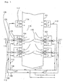
- Reference numeral 01 denotes a boiler furnace main body, and a plurality of burner main bodies 02 are disposed in a vertical direction at each of four corners therein.
- the burner main body 02 is constituted by a combustion air nozzle 03. an auxiliary air nozzle 04. a pulverized coal mixture nozzle 05. etc. and a pulverized coal mixture 10.
- a combustion air 11, a main burner air 12 and an additional air 13 are supplied thereto through a pulverized coal mixture feeding pipe 06, an air feeding duct 07, a main burner air duct 08 and an additional air duct 09.
- Reference numeral 14 denotes an additional air nozzle disposed at an upper position
- reference numeral 15 denotes a furnace
- a pulverized coal flame 16 is formed in the furnace 15.
- Reference numeral 17 denotes an air adjusting damper assembled in each of the burner main bodies 02.
- reference numeral 18 denotes an imaginary circle imagined in the furnace 15 for explanation purpose, and reference numeral 19 denotes a fire vortex formed in the furnace 15.
- a coal fed to a coal pulverizing apparatus (not shown) is finely pulverized, is mixed with a carrying air (a hot air) simultaneously fed so as to form the pulverized coal mixture 10, and is fed to the pulverized coal mixture nozzle 05 provided in the burner main body 02 through the pulverized coal mixture feeding pipe 06.
- the burner main bodies 02 are provided.at four corners of the boiler furnace main body 01. and plural sets of burners, each burner comprising the combustion air nozzle 03, the pulverized coal mixture nozzle 05 provided in a center portion thereof and the auxiliary air nozzle 04 provided above and below the combustion air nozzle 03, are installed within each of the burner main bodies 02. (Here, there is a case that the burner main bodies 02 are provided not only at four corners of the boiler furnace main body 01, but also on a wall surface as shown in Fig. 9.)
- Each set of these nozzles that is, the combustion air nozzle 03, the auxiliary air nozzle 04 and the pulverized coal mixture nozzle 05, is installed in such a manner as to blow the pulverized coal mixture 10 and the main burner air 12 in a tangential direction of an imaginary circle 18 which is set at a center portion on a horizontal cross section of the boiler furnace main body 01.
- a construction drawing of the conventional pulverized coal mixture nozzle 05 will be shown in Fig. 10.
- the additional air nozzles 14 are provided at four corners above the burner main bodies 02 in the boiler furnace main body 01.
- the additional air nozzle 14 is installed in such a manner as to blow the additional air 13 in a tangential direction of an imaginary circle 18 which has a same diameter as that of the imaginary circle 18 with respect to the respective nozzles 03, 04 and 05 of the burner main body 02 and is set at a center portion on a horizontal cross section of the boiler furnace main body 01.
- the pulverized coal mixture 10 supplied to the pulverized coal mixture nozzle 05 provided in the burner main body 02 is blown into the furnace 15 from the nozzle 05.
- the combustion air 11 is fed through the air feeding duct 07 by a feeding apparatus (not shown), and is branched into the main burner air 12 and the additional air 13 before entering the burner main body 02.
- the main burner air 12 is fed to the burner main body 02 through the main burner air duct 08, and is blown into the furnace 15 from the combustion air nozzle 03 and the auxiliary air nozzle 04.
- An amount of the main burner air 12 is generally set to be equal to or less than a stoichiometric mixture ratio of an amount of the pulverized coal blown as the pulverized coal mixture 10 so as to hold a portion of the furnace 15 below the additional air nozzle 14 in a reducing atmosphere, thereby reducing a nitrogen oxide (hereinafter referred to as to NOx for short) generated by burning the pulverized coal.
- NOx nitrogen oxide
- the main burner air 12 and the branched additional air 13 are fed to the additional air nozzle 14, and blown into the furnace 15 so as to be used for completing a burning of a combustible portion left in the combustion gas due to the reduction combustion.
- the pulverized coal mixture 10 blown into the furnace 15 from the four corners of the boiler furnace main body 01 is ignited by an ignition source (not shown), and forms the pulverized coal flame 16.
- the pulverized coal flame 16 becomes a swirling flow so as to form the fire vortex 19, and ascend in the furnace 15 with swirling, thereby performing a swirling combustion.
- the amount of the main burner air 12 blown from the burner main body 02 is equal to or less than the stoichiometric mixture ratio of the amount of the pulverized coal blown as the pulverized coal mixture 10 from the pulverized coal mixture nozzle 05, so that the portion of the furnace 15 below the additional air nozzle 14 portion becomes a reducing atmosphere.
- a combustion exhaust gas generated by burning the pulverized coal becomes to contain a combustible portion, however, NOx in the combustion exhaust gas generated by burning the pulverized coal is reduced so that an intermediate product such as NH3 and HCN is generated in place thereof.
- the combustion exhaust gas containing the combustible portion is blown with the additional air 13 in the additional air nozzle 14 portion, and the combustion thereof is completed till an outlet of the furnace.
- the conventional pulverized coal burner Since a blowing momentum of the pulverized coal mixture 10 blown from the pulverized coal mixture nozzle 05 becomes large when a capacity of the burner becomes large, a degree of collision of the pulverized coal flame 16 with side wall of the furnace 15 is increased, and in addition thereto, it becomes difficult to secure a stable ignitability. As a result, the conventional pulverized coal burner has a disadvantage that it is hard to increase the capacity.
- the increase of the number of the burners is performed by increasing a number of stages of the burners since the number of the burners on the horizontal cross section of the boiler furnace main body 01 is fixed, however, in this manner, a height of the boiler is increased, so that a cost for constructing the boiler is increased.
- US-A-5 593 298 discloses a furnace including a pulverized coal burner with the features of the preamble portion of claim 1.
- a fuel nozzle is arranged so as to be surrounded by an air passage for discharging a fuel stream and a surrounding air stream.
- this prior art teaches to use restricting blades to create an eccentric distribution of air by partially restricting or blocking the flow.
- the central coal mixture nozzle itself is symmetrically arranged with respect to the surrounding air nozzles.
- the present invention provides a furnace including a pulverized coal burner as defined in claim 1.
- a furnace including a pulverized coal burner as defined in claim 1.
- Preferred embodiments are defined in the dependent claims.
- the invention provides a furnace with a pulverized coal burner for supplying a pulverized coal mixture in a tangential direction of an imaginary circle in a horizontal plane of the furnace so as to be burned, wherein a pulverized coal mixture nozzle is made eccentric with respect to an air nozzle so that the pulverized coal mixture becomes rich on a central side of the imaginary circle.
- an axis of the pulverized coal mixture nozzle and an axis of the air nozzle are moved and shifted to be eccentric with each other so that a concentration of the pulverized coal of the pulverized coal mixture blown to an outer peripheral side of a fire vortex (near the wall surface of the furnace) formed in the furnace from the pulverized coal mixture nozzle is reduced and a concentration of the pulverized coal blown to an inner portion side of the fire vortex becomes rich, thereby the pulverized coal flame is prevented from colliding with the furnace wall and an amount of an air near the inner wall surface of the furnace is increased to form an oxidation atmosphere. Therefore, the molten ash is prevented from attaching by increasing an ash melting point.
- the invention provides a pulverized coal burner with a means for applying a swirl to a combustion air supplied from an outer periphery of the pulverized coal mixture nozzle. Accordingly, an ignition stability with an increased capacity of a burner, a flame stability at a time of load changes, a short flame and a lowness of soot and dust can be secured by applying a swirl to the combustion air and by using, for example, a combined flame stabilizer, if necessary.
- the invention provides a pulverized coal burner with a means for directing a front end portion of the burner in vertical and lateral directions. Accordingly, a position of the fire vortex can be changed by making the structure capable of changing the nozzle direction in the vertical and lateral directions, so that a distribution of the thermal load in the furnace can be adjusted.
- reference numerals 101 to 119 correspond to the reference numerals 01 to 19 in the conventional structure, a description will be simplified as much as possible, and an ignition promoting air hole 120 provided in a pulverized coal mixture nozzle 105, an ignition promoting air chamber 121, an ignition promoting air chamber inlet port 122, a guiding plate 123. a rich/lean separating body 124, etc. will be described in detail.
- a coal fed to a coal pulverizing apparatus (not shown) is pulverized there, is mixed with a carrying air (a hot air) simultaneously fed so as to form a pulverized coal mixture 110. and is fed to a pulverized coal mixture nozzle 105 provided in a burner main body 102 through a pulverized coal mixture transporting pipe 106.
- the pulverized coal mixture nozzle 105 is constituted by a pulverized coal mixture pipe connected to the pulverized coal mixture transporting pipe 106, and a mixture injecting nozzle attached to a front end thereof.
- the rich/lean separating body 124 is provided within the pulverized coal mixture pipe near an inlet of the mixture injecting nozzle.
- An injecting port of the mixture injecting nozzle is branched into upper and lower directions with an optional angle, for example, an angle of 10 degrees to 30 degrees in one direction with respect to a horizontal axis, and the ignition promoting air chamber 121 is provided between the upper and lower injecting ports.
- the combustion air nozzle 103 is provided on an outer periphery of the mixture injecting nozzle, and blows the main burner air 112 into the furnace 114 from a blowing port constituted by the mixture injecting nozzle and the combustion air nozzle 103.
- the pulverized coal mixture 110 fed to the pulverized coal mixture nozzle 105 flows in a biased manner at the pulverized coal mixture pipe outlet portion by the rich/lean separating body 124.
- the pulverized coal mixture 110 is structured such that a concentration of the pulverized coal becomes lean on the rich/lean separating body 124 attaching side at the mixture injecting nozzle outlet port due to a force of inertia and a concentration of the pulverized coal on the opposite side not attaching the same becomes rich.
- a blowing port of the main burner air 112 formed by the mixture injecting nozzle and the combustion air nozzle 103 is formed wider on the lean pulverized coal side of the pulverized coal mixture 110 and narrower on the rich pulverized coal side.
- a portion, blown into a central side of the fire vortex 119, of the pulverized coal mixture 110 injected from the mixture injecting nozzle becomes to an upstream side of the swirling combustion flow, so that said portion is in a state of easily igniting having a large radiant heat from the adjacent pulverized coal flame 116.
- the pulverized coal mixture 110 is set such that the rich pulverized coal side is blown to the central side of the fire vortex 119.
- a new device is further added to the mixture injecting nozzle in order to improve an ignition stability of the pulverized coal flame 116.
- the mixture injecting nozzle is structured such that the injecting port thereof is branched to the upper and lower directions with an optional angle, the ignition promoting air chamber 121 is provided between the upper and lower injecting ports, and the guiding plate 123 and the ignition promoting air chamber inlet hole 122 are provided in the inlet of said air chamber 121.
- the ignition promoting air chamber 121 is formed by disposing a plate on a side facing to the the furnace 115. and the ignition promoting air hole 120 is bored on the plate so as to blow the main burner air 112. which has flown to the ignition promoting air chamber 121 through the ignition promoting air chamber inlet hole 122, between two pulverized coal mixtures 110 injected from the mixture injecting nozzle.
- the main burner air 112 blown from the ignition promoting air hole 120 prevents flows of the pulverized coal mixture 110 blown from two injection ports of the mixture injecting nozzle from joining together earlier, and since a temperature of the main burner air 112 is high to be about 300 °C in comparison that a temperature of the pulverized coal mixture 110 is generally 100 °C or less (in many cases, about 80 °C), an effect that a generation of a volatile matter between the pulverized coal mixtures 110 is promoted can be obtained, so that an igniting stability of the pulverized coal flame 116 can be secured.
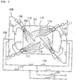
- Reference numeral 201 denotes a pulverized coal mixture nozzle, and a secondary air nozzle 202 and a tertiary air nozzle 203 are arranged in a periphery thereof.
- Reference numeral 204 denotes a swirler, arranged at an upstream position of an outlet of the tertiary air nozzle 203.
- Reference numeral 205 denotes a hollow core provided at an upstream position of an outlet of the pulverized coal mixture nozzle 201.
- Reference numeral 206 denotes a tilt bar connected to a spherical connecting portion 210 at a front end portion of each of the nozzles 201, 202 and 203. and each of the nozzles 201, 202 and 203 can be directed in a vertical direction around the connecting portion 210 by moving the tilt bar 206 laterally as shown by arrows in the drawing.
- a tilt bar 206 connected to the tertiary air nozzle 203 operates a motion in the vertical direction of the tertiary air nozzle 203, and the pulverized coal mixture nozzle 201 and the secondary air nozzle 202 are interlocked by a supporting rod 207 and the tilt bar 206 is connected to the secondary air nozzle 202, thereby the pulverized coal mixture nozzle 201 together with the secondary air nozzle 202 change the direction in the vertical direction.
- reference numeral 208 denotes a flame stabilizer, arranged at the front end of each of the nozzles 201. 202 and 203, for serving a flame stabilizing effect.
- a concentration distribution of the pulverized coal in the pulverized coal mixture injecting flow is made rich on the peripheral side, and by the flame stabilizer 208, an ignition stability is increased.
- the injecting direction of the pulverized coal mixture, the secondary air and the tertiary air can be changed in the vertical and lateral directions by moving the tilt bar 206 in the front and rear direction.
- the pulverized coal mixture nozzle and the secondary air nozzle are interlocked to be fixed together by the supporting rod 107, the injecting flow therefrom is directed in the same direction.
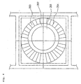
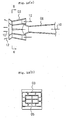
- FIG. 6(a) shows a cross section of a boiler
- Fig. 6(b) shows a burner windbox arranged at each of four corners of Fig. 6(a) and a separately provided additional air port arranged above the burner windbox
- Fig. 6(c) shows a front of one of fuel nozzles of Fig. 6(b)
- Fig. 6(d) shows a pulverized fuel pipe for supplying a fuel to the fuel nozzle of Fig. 6(c).
- reference numeral 301 denotes a cross section of a furnace, a periphery of which is surrounded by a wall of the furnace in a square shape, and a burner windbox 302 is arranged at each of four corners thereof.
- Reference numeral 303 denotes a flame and reference numeral 304 denotes a section close to the furnace wall.
- Fig. 6(b) shows a detail of the burner windbox 302 structured in five stages. That is, auxiliary air portions 305b and 305a are arranged at upper and lower ends, a first stage fuel nozzle portion 306a is placed on the lower end auxiliary air portion 305a. a second stage fuel nozzle portion 306b is placed thereon via an oil nozzle portion 307a. and a third stage fuel nozzle portion 306c. a fourth stage fuel nozzle portion 306d and a fifth stage fuel nozzle portion 306e are likewise placed via an oil nozzle portion 307b, an oil nozzle portion 307c and an oil nozzle portion 307d, respectively, up to the upper end auxiliary air portion 305b overlappedly with no gap being placed between each of them.
- the fifth stage fuel nozzle portion 306e is constituted by a fuel injecting port 308, disposed in a central portion, for injecting a pulverized fuel and a carrying air, and a combustion secondary air injecting port 309, surrounding a periphery thereof, for injecting a secondary air.
- the other fuel nozzle portions 306a to 306d are also constituted in the same manner as that of the fifth stage fuel nozzle portion 306e. Further, the pulverized fuel and the carrying air to be injected from the fuel injecting port 308 are carried through the pulverized fuel pipe 310 shown in Fig. 6(d) and reach the fuel injecting port 308.
- the furnace cross section 301 the periphery of which is surrounded by the furnace wall in a square shape, is provided with the burner windbox 302 at each of four corners, however, the first to fifth stage fuel nozzle portions 306a to 306e, which constitute a main portion of the burner disposed here, and the respective oil nozzle portions 307a to 307d disposed therebetween are structured with an elongated horizontal width and a reduced height.
- the horizontal width is made to be 1 to 1.5 times the height, however, in this embodiment, the shape is formed such that the horizontal width is made to be about three times the height, and the height is reduced corresponding to the horizontal width, so elongated, so that the total height of the five stages is made lower.
- an additional air port 314 is provided above the burner windbox 302 constructed in five stages overlappedly, and the position of the additional air port 314 is set to be substantially same as the height at which the uppermost element of the conventional general fuel nozzle portions is arranged.
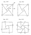
- the hatched fifth stage fuel nozzle portion 306e in the overlapped body is structured such that the front shape is constituted, as shown in Fig. 1(c), by the fuel injecting port 308. arranged on the inner side, for injecting the pulverized fuel and the carrying air, and the combustion secondary air injecting port 309. surrounding the fuel injecting port 308, for injecting the secondary air, however, the fuel injecting port 308 on the inner side is biased rightward as seen in the drawing in the fuel secondary air injecting port 309. surrounding the fuel injecting port 308.
- the structure is such that an opening portion of the fuel secondary air injecting port 309 is broader in a portion close to the furnace wall and a portion close to the center is narrower by that degree, so that the combustion secondary air is injected more to the portion close to the furnace wall by increasing an air flow area in the portion close to the furnace wall, and a lean fuel flame 311 is formed within the section 304 close to the furnace wall on the furnace wall side of the flame 303 around the center.
- a block 313 is disposed at a portion at which a flow of the pulverized fuel and the carrying air curves, so that the pulverized fuel etc. is biased outwardly of the curved portion above the block by a centrifugal force and then, by use of a twist plate 312 which is arranged so as to twist a flow 90 degrees, the rich pulverized fuel etc. is biased to the inner side of the furnace and the concentration thereof in the portion close to the furnace wall is reduced.
- the pulverized fuel flows with an increased area for receiving a radiation heat from the flame so as to promote the ignition by expanding the width of the so-called burner portion comprising the first to fifth stage fuel nozzle portions 306a to 306e and by reducing the height of the burner, and a combustion is done in a narrow area, thereby elevating an atmospheric temperature and improving a combustibility.
- the additional air port 314 installed separately from the burner portion is provided at the height position substantially corresponding to the uppermost stage of the conventional general burners and a sufficient amount of air corresponding to about 30 to 40 % of all the combustion air is supplied there, thereby making the burner portion a reducing area with a shortage of air, and further, reduction of the height of the entire burner portion secures a residence time for the pulverized fuel and the combustion gas moving from the burner portion to the additional air port 314, so that the NOx reducing area is further strengthened in addition to the promotion of ignition and the increase of the atmospheric temperature.
- twist plate 312 and the block 313 disposed inside the pulverized fuel pipe 310 first bias the pulverized fuel within the cross section of the pulverized fuel pipe 310 by a centrifugal force due to the block 313 and the curve of the pulverized fuel pipe 310, and next the twist plate 312 twists the pulverized fuel in the rich area to be injected to the inner side of the furnace, and reduces the pulverized fuel amount near the furnace wall, so that amount of ash content is reduced also.
- a compound having a low melting temperature is formed in a state that the peripheral atmosphere is short of air and a bonding force is increased, so that an air amount close to the furnace wall where the opening area is broad is increased, and such component is prevented from occurring with the sufficient air.
- the axis of the pulverized coal mixture nozzle and the axis of the air nozzle are shifted to be eccentric with each other so that the concentration of the pulverized coal in the pulverized coal mixture blown from the pulverized coal mixture nozzle to the portion on the outer peripheral side of the fire vortex formed in the furnace, that is, the portion close to the wall surface of the furnace is made lean and the concentration of the pulverized coal blown to the portion the inner side of the fire vortex is made rich, thereby the pulverized coal flame is prevented from colliding with the furnace wall and the air amount near the furnace wall is increased so as to form an oxidation atmosphere and increase the ash melting point, and the molten slag is prevented from attaching.
- the structure for freely changing the direction of the front end portion of the burner in the vertical and lateral directions is employed, the optimum position of the nozzle opening is selected in accordance with the condition, the position of the fire vortex can be changed and the distribution of the thermal load within the furnace can be adjusted.
Landscapes
- Engineering & Computer Science (AREA)
- Chemical & Material Sciences (AREA)
- Combustion & Propulsion (AREA)
- Mechanical Engineering (AREA)
- General Engineering & Computer Science (AREA)
Claims (5)
- Ofen mit einem Kohlestaubbrenner (102), der so angeordnet ist, dass er ein Kohlestaubgemisch (110) in einer Tangentialrichtung eines imaginären Kreises (118) in einer Horizontalebene des Ofens (115;301) zuführt, um es zu verbrennen,
wobei der Kohlestaubbrenner (102) eine Kohlestaub-Gemischdüse (105;201;308) und eine die Kohlestaub-Gemischdüse (105;201;308) an deren Außenumfang umgebende Luftdüse (103;203;309) aufweist,
dadurch gekennzeichnet, dass die Kohlestaub-Gemischdüse (105;201;308) exzentrisch in bezug auf die Luftdüse (103;203;309) angeordnet ist. - Kohlestaubbrenner nach Anspruch 1, dadurch gekennzeichnet, dass ein Mittel (204) zum Anlegen eines Wirbelstroms an eine von einem Außenumfang der Kohlestaub-Gemischdüse (201) zugeführte Verbrennungsluft vorgesehen ist.
- Kohlestaubbrenner nach Anspruch 1 oder 2, dadurch gekennzeichnet, dass ein Mittel (206) zum Ausrichten eines Vorderendabschnitts des Kohlestaubbrenners in Vertikal- und Lateralrichtungen vorgesehen ist.
- Kohlestaubbrenner nach Anspruch 1 oder 2, dadurch gekennzeichnet, dass ein Mittel (206) zum unabhängigen Ausrichten der Kohlestaub-Gemischdüse (201) und der Luftdüse (203) in Vertikal- und Lateralrichtungen vorgesehen ist.
- Kohlestaubbrenner nach Anspruch 3 oder 4, dadurch gekennzeichnet, dass das Mittel zum Ausrichten eine Schwenk- bzw. Kippstange (206) umfasst, die mit einem kugelförmigen Verbindungsabschnitt (210) an einem Vorderende jeder der Düsen (201;203) verbunden ist.
Priority Applications (1)
| Application Number | Priority Date | Filing Date | Title |
|---|---|---|---|
| EP02006378A EP1219893B1 (de) | 1998-07-29 | 1998-07-29 | Kohlenstaubbrenner |
Applications Claiming Priority (2)
| Application Number | Priority Date | Filing Date | Title |
|---|---|---|---|
| EP19980114219 EP0976977B1 (de) | 1998-07-29 | 1998-07-29 | Kohlenstaubbrenner |
| EP02006378A EP1219893B1 (de) | 1998-07-29 | 1998-07-29 | Kohlenstaubbrenner |
Related Parent Applications (2)
| Application Number | Title | Priority Date | Filing Date |
|---|---|---|---|
| EP19980114219 Division EP0976977B1 (de) | 1998-07-29 | 1998-07-29 | Kohlenstaubbrenner |
| EP98114219.3 Division | 1998-07-29 |
Publications (2)
| Publication Number | Publication Date |
|---|---|
| EP1219893A1 EP1219893A1 (de) | 2002-07-03 |
| EP1219893B1 true EP1219893B1 (de) | 2006-01-18 |
Family
ID=8232370
Family Applications (3)
| Application Number | Title | Priority Date | Filing Date |
|---|---|---|---|
| EP02006378A Expired - Lifetime EP1219893B1 (de) | 1998-07-29 | 1998-07-29 | Kohlenstaubbrenner |
| EP02006379A Expired - Lifetime EP1219894B1 (de) | 1998-07-29 | 1998-07-29 | Kohlenstaubbrenner |
| EP19980114219 Expired - Lifetime EP0976977B1 (de) | 1998-07-29 | 1998-07-29 | Kohlenstaubbrenner |
Family Applications After (2)
| Application Number | Title | Priority Date | Filing Date |
|---|---|---|---|
| EP02006379A Expired - Lifetime EP1219894B1 (de) | 1998-07-29 | 1998-07-29 | Kohlenstaubbrenner |
| EP19980114219 Expired - Lifetime EP0976977B1 (de) | 1998-07-29 | 1998-07-29 | Kohlenstaubbrenner |
Country Status (1)
| Country | Link |
|---|---|
| EP (3) | EP1219893B1 (de) |
Cited By (1)
| Publication number | Priority date | Publication date | Assignee | Title |
|---|---|---|---|---|
| DE102010052464A1 (de) * | 2010-11-24 | 2012-05-24 | Ludwig Müller | Dreh-Strom-Feuerung (DSF) |
Families Citing this family (22)
| Publication number | Priority date | Publication date | Assignee | Title |
|---|---|---|---|---|
| AU6005301A (en) * | 2000-04-12 | 2001-10-23 | Saar Energie Gmbh | Method for burning particulate fuel in a power station boiler |
| DE10019114A1 (de) * | 2000-04-18 | 2001-10-25 | Bbp Energy Gmbh | Feuerung und Verfahren zur Verbrennung von Kohlenstaub |
| SK287642B6 (sk) * | 2000-08-04 | 2011-05-06 | Babcock-Hitachi Kabushiki Kaisha | Horák na tuhé palivo a spôsob spaľovania horákom na tuhé palivo |
| FR2848641B1 (fr) * | 2002-12-11 | 2005-12-16 | Alstom Switzerland Ltd | Systeme de chauffe indirecte avec valorisation des particules de combustible ultra fines |
| EP1898150A4 (de) * | 2005-06-03 | 2010-08-11 | Zakrytoe Aktsionernoe Obschest | Befeuerter dampferzeuger |
| CN101598333B (zh) * | 2009-06-30 | 2012-09-26 | 上海锅炉厂有限公司 | 一种低氮氧化物排放煤粉切向燃烧装置 |
| JP2011127836A (ja) * | 2009-12-17 | 2011-06-30 | Mitsubishi Heavy Ind Ltd | 固体燃料焚きバーナ及び固体燃料焚きボイラ |
| JP5374404B2 (ja) | 2009-12-22 | 2013-12-25 | 三菱重工業株式会社 | 燃焼バーナおよびこの燃焼バーナを備えるボイラ |
| MX354826B (es) * | 2011-04-01 | 2018-03-21 | Mitsubishi Heavy Ind Ltd | Quemador de combustión, quemador de combustión de combustible sólido, hervidor de combustión de combustible sólido, hervidor y método para poner en operación el hervidor. |
| JP5800423B2 (ja) * | 2011-11-29 | 2015-10-28 | 三菱日立パワーシステムズ株式会社 | バーナおよびこれを備えたボイラ |
| US9377191B2 (en) | 2013-06-25 | 2016-06-28 | The Babcock & Wilcox Company | Burner with flame stabilizing/center air jet device for low quality fuel |
| CN103322561A (zh) * | 2013-07-04 | 2013-09-25 | 哈尔滨锅炉厂有限责任公司 | 双腔深度分级煤粉燃烧装置 |
| JP6087793B2 (ja) * | 2013-11-15 | 2017-03-01 | 三菱日立パワーシステムズ株式会社 | ボイラ |
| CN104494034B (zh) * | 2014-12-26 | 2016-08-31 | 东莞市秋天塑胶材料有限公司 | Pvc发泡炉供热系统 |
| DE102015226566A1 (de) * | 2015-12-22 | 2017-06-22 | Siemens Aktiengesellschaft | Abgeknickter Hauptbrenner |
| RU2635947C2 (ru) * | 2016-04-12 | 2017-11-17 | федеральное государственное автономное образовательное учреждение высшего образования "Южно-Уральский государственный университет" (национальный исследовательский университет) | Котел и способ его работы |
| JP6879771B2 (ja) * | 2017-02-17 | 2021-06-02 | 三菱パワー株式会社 | 燃焼バーナ及びこれを備えたボイラ |
| CN107083258B (zh) * | 2017-06-23 | 2024-03-26 | 航天长征化学工程股份有限公司 | 一种气化烧嘴装置 |
| EP3438533B1 (de) | 2017-07-31 | 2021-03-03 | General Electric Technology GmbH | Kohledüsenanordnung für eine dampferzeugungsvorrichtung |
| CN109458612A (zh) * | 2017-09-06 | 2019-03-12 | 晋能电力集团有限公司 | 一种煤粉气化燃烧的低氮燃烧装置及燃烧方法 |
| CN108397766B (zh) * | 2018-03-01 | 2020-06-05 | 中国神华能源股份有限公司 | 锅炉以及锅炉的配风方法 |
| CN113790440A (zh) * | 2021-10-26 | 2021-12-14 | 西安热工研究院有限公司 | 一种煤粉燃烧器的一次风喷口 |
Family Cites Families (8)
| Publication number | Priority date | Publication date | Assignee | Title |
|---|---|---|---|---|
| US2343572A (en) * | 1940-07-01 | 1944-03-07 | Comb Eng Co Inc | Finely divided fuel burner |
| DE890254C (de) * | 1950-03-05 | 1953-09-17 | Kohlenscheidungs Ges M B H | Verfahren und Einrichtung zum Betrieb von Kohlenstaubfeuerungen fuer Hochleistungs-Dampfkessel |
| JPS58129105A (ja) * | 1982-01-29 | 1983-08-02 | Mitsubishi Heavy Ind Ltd | 微粉炭焚タンゼンシヤルフアイアリングボイラの燃焼方法 |
| DE3920798A1 (de) * | 1989-06-24 | 1991-01-10 | Balcke Duerr Ag | Vorrichtung zur verbrennung von brennstoffen in einer brennkammer |
| US5315939A (en) * | 1993-05-13 | 1994-05-31 | Combustion Engineering, Inc. | Integrated low NOx tangential firing system |
| US5329866A (en) * | 1993-09-03 | 1994-07-19 | The Babcock & Wilcox Company | Combined low NOx burner and NOx port |
| JPH08178210A (ja) * | 1994-12-26 | 1996-07-12 | Mitsubishi Heavy Ind Ltd | 旋回燃焼火炉用バーナ装置 |
| US5593298A (en) * | 1995-04-10 | 1997-01-14 | Combustion Components Associates, Inc. | Pollutant reducing modification of a tangentially fired furnace |
-
1998
- 1998-07-29 EP EP02006378A patent/EP1219893B1/de not_active Expired - Lifetime
- 1998-07-29 EP EP02006379A patent/EP1219894B1/de not_active Expired - Lifetime
- 1998-07-29 EP EP19980114219 patent/EP0976977B1/de not_active Expired - Lifetime
Cited By (1)
| Publication number | Priority date | Publication date | Assignee | Title |
|---|---|---|---|---|
| DE102010052464A1 (de) * | 2010-11-24 | 2012-05-24 | Ludwig Müller | Dreh-Strom-Feuerung (DSF) |
Also Published As
| Publication number | Publication date |
|---|---|
| EP0976977A1 (de) | 2000-02-02 |
| EP1219894A1 (de) | 2002-07-03 |
| EP1219893A1 (de) | 2002-07-03 |
| EP0976977B1 (de) | 2003-03-26 |
| EP1219894B1 (de) | 2006-04-05 |
Similar Documents
| Publication | Publication Date | Title |
|---|---|---|
| EP1219893B1 (de) | Kohlenstaubbrenner | |
| US6699031B2 (en) | NOx reduction in combustion with concentrated coal streams and oxygen injection | |
| EP1537362B1 (de) | Verbrennung mit geringem nox-ausstoss | |
| JP3664832B2 (ja) | 微粉炭バーナ | |
| EP0933592B1 (de) | Verfahren zur Verbrennung von Kohlenstaub | |
| BG64878B1 (bg) | Горелка за твърдо гориво и метод за регулиране нагоренето, осъществявано от горелката за твърдо гориво | |
| JP2004205161A (ja) | 固体燃料ボイラ及びボイラ燃焼方法 | |
| KR20070105868A (ko) | 초저 NOx 버너 조립체 | |
| PL185103B1 (pl) | Sposób spalania mieszanki paliwowej w strumieniu powietrza i palnik do spalania mieszanki paliwowej w strumieniu powietrza | |
| KR20020000758A (ko) | 접촉 연소 시스템 작동 방법 | |
| JP5386230B2 (ja) | 燃料バーナ及び旋回燃焼ボイラ | |
| JP2540636B2 (ja) | ボイラ | |
| CA2509631C (en) | Process and apparatus for oxygen enrichment in fuel conveying gases | |
| JP3679998B2 (ja) | 微粉炭バーナ | |
| JP2006337016A (ja) | 炉燃焼システム及び燃料燃焼方法 | |
| JPH0783405A (ja) | 低NOxバーナーとNOxポートの組合せ体 | |
| JP2010270990A (ja) | 燃料バーナ及び旋回燃焼ボイラ | |
| JP2731794B2 (ja) | NOx制御用の高性能オーバファイア空気システム | |
| JP2023523153A (ja) | バーナー内に燃料流分配手段を有するボイラの燃焼システム及び燃焼方法 | |
| WO2000061992A1 (en) | Tunneled multi-blade swirler/gas injector for a burner | |
| KR100231975B1 (ko) | 선화분사 구멍을 가진 질소산화물 저감형 이단노즐 | |
| JP3524682B2 (ja) | 微粉状燃料燃焼装置 | |
| CN115164592B (zh) | 一种分解炉二次全氧燃烧富集co2的系统与方法 | |
| TW202338263A (zh) | 氨燃燒噴燃器及鍋爐 | |
| JPH0366565B2 (de) |
Legal Events
| Date | Code | Title | Description |
|---|---|---|---|
| PUAI | Public reference made under article 153(3) epc to a published international application that has entered the european phase |
Free format text: ORIGINAL CODE: 0009012 |
|
| 17P | Request for examination filed |
Effective date: 20020321 |
|
| AC | Divisional application: reference to earlier application |
Ref document number: 976977 Country of ref document: EP |
|
| AK | Designated contracting states |
Kind code of ref document: A1 Designated state(s): BE NL |
|
| AKX | Designation fees paid |
Designated state(s): BE NL |
|
| 17Q | First examination report despatched |
Effective date: 20040402 |
|
| GRAP | Despatch of communication of intention to grant a patent |
Free format text: ORIGINAL CODE: EPIDOSNIGR1 |
|
| RIN1 | Information on inventor provided before grant (corrected) |
Inventor name: ICHINOSE, TOSHIMITSU,C/O MITSUBISHI HEAVY IND. Inventor name: OKAMOTO, AKIYASU,C/O MITSUBISHI HEAVY INDUSTRIES Inventor name: SUZUKI, TAKESHI,C/O MITSUBISHI HEAVY INDUSTRIES Inventor name: OGURI, MASAHARU,C/O CHORYO ENGINEERING CO., LTD. |
|
| GRAS | Grant fee paid |
Free format text: ORIGINAL CODE: EPIDOSNIGR3 |
|
| GRAA | (expected) grant |
Free format text: ORIGINAL CODE: 0009210 |
|
| AC | Divisional application: reference to earlier application |
Ref document number: 0976977 Country of ref document: EP Kind code of ref document: P |
|
| AK | Designated contracting states |
Kind code of ref document: B1 Designated state(s): BE NL |
|
| PLBE | No opposition filed within time limit |
Free format text: ORIGINAL CODE: 0009261 |
|
| STAA | Information on the status of an ep patent application or granted ep patent |
Free format text: STATUS: NO OPPOSITION FILED WITHIN TIME LIMIT |
|
| 26N | No opposition filed |
Effective date: 20061019 |
|
| PGFP | Annual fee paid to national office [announced via postgrant information from national office to epo] |
Ref country code: NL Payment date: 20080715 Year of fee payment: 11 |
|
| PGFP | Annual fee paid to national office [announced via postgrant information from national office to epo] |
Ref country code: BE Payment date: 20090126 Year of fee payment: 11 |
|
| BERE | Be: lapsed |
Owner name: *MITSUBISHI HEAVY INDUSTRIES LTD Effective date: 20090731 |
|
| NLV4 | Nl: lapsed or anulled due to non-payment of the annual fee |
Effective date: 20100201 |
|
| PG25 | Lapsed in a contracting state [announced via postgrant information from national office to epo] |
Ref country code: BE Free format text: LAPSE BECAUSE OF NON-PAYMENT OF DUE FEES Effective date: 20090731 |
|
| PG25 | Lapsed in a contracting state [announced via postgrant information from national office to epo] |
Ref country code: NL Free format text: LAPSE BECAUSE OF NON-PAYMENT OF DUE FEES Effective date: 20100201 |