EP1219513A2 - Wiper assembly for vehicle - Google Patents
Wiper assembly for vehicle Download PDFInfo
- Publication number
- EP1219513A2 EP1219513A2 EP01310858A EP01310858A EP1219513A2 EP 1219513 A2 EP1219513 A2 EP 1219513A2 EP 01310858 A EP01310858 A EP 01310858A EP 01310858 A EP01310858 A EP 01310858A EP 1219513 A2 EP1219513 A2 EP 1219513A2
- Authority
- EP
- European Patent Office
- Prior art keywords
- wiper
- vehicle
- vehicle body
- vicinity
- motor
- Prior art date
- Legal status (The legal status is an assumption and is not a legal conclusion. Google has not performed a legal analysis and makes no representation as to the accuracy of the status listed.)
- Granted
Links
- 238000010521 absorption reaction Methods 0.000 description 2
- 230000004048 modification Effects 0.000 description 1
- 238000012986 modification Methods 0.000 description 1
Images



Classifications
-
- B—PERFORMING OPERATIONS; TRANSPORTING
- B60—VEHICLES IN GENERAL
- B60S—SERVICING, CLEANING, REPAIRING, SUPPORTING, LIFTING, OR MANOEUVRING OF VEHICLES, NOT OTHERWISE PROVIDED FOR
- B60S1/00—Cleaning of vehicles
- B60S1/02—Cleaning windscreens, windows or optical devices
- B60S1/04—Wipers or the like, e.g. scrapers
- B60S1/0488—Wiper arrangement for crash protection or impact absorption
-
- B—PERFORMING OPERATIONS; TRANSPORTING
- B60—VEHICLES IN GENERAL
- B60S—SERVICING, CLEANING, REPAIRING, SUPPORTING, LIFTING, OR MANOEUVRING OF VEHICLES, NOT OTHERWISE PROVIDED FOR
- B60S1/00—Cleaning of vehicles
- B60S1/02—Cleaning windscreens, windows or optical devices
- B60S1/04—Wipers or the like, e.g. scrapers
- B60S1/043—Attachment of the wiper assembly to the vehicle
- B60S1/0433—Attachement of a wiper modular assembly to the vehicle
-
- F—MECHANICAL ENGINEERING; LIGHTING; HEATING; WEAPONS; BLASTING
- F16—ENGINEERING ELEMENTS AND UNITS; GENERAL MEASURES FOR PRODUCING AND MAINTAINING EFFECTIVE FUNCTIONING OF MACHINES OR INSTALLATIONS; THERMAL INSULATION IN GENERAL
- F16B—DEVICES FOR FASTENING OR SECURING CONSTRUCTIONAL ELEMENTS OR MACHINE PARTS TOGETHER, e.g. NAILS, BOLTS, CIRCLIPS, CLAMPS, CLIPS OR WEDGES; JOINTS OR JOINTING
- F16B2200/00—Constructional details of connections not covered for in other groups of this subclass
- F16B2200/63—Frangible connections
-
- Y—GENERAL TAGGING OF NEW TECHNOLOGICAL DEVELOPMENTS; GENERAL TAGGING OF CROSS-SECTIONAL TECHNOLOGIES SPANNING OVER SEVERAL SECTIONS OF THE IPC; TECHNICAL SUBJECTS COVERED BY FORMER USPC CROSS-REFERENCE ART COLLECTIONS [XRACs] AND DIGESTS
- Y10—TECHNICAL SUBJECTS COVERED BY FORMER USPC
- Y10S—TECHNICAL SUBJECTS COVERED BY FORMER USPC CROSS-REFERENCE ART COLLECTIONS [XRACs] AND DIGESTS
- Y10S248/00—Supports
- Y10S248/90—Movable or disengageable on impact or overload
-
- Y—GENERAL TAGGING OF NEW TECHNOLOGICAL DEVELOPMENTS; GENERAL TAGGING OF CROSS-SECTIONAL TECHNOLOGIES SPANNING OVER SEVERAL SECTIONS OF THE IPC; TECHNICAL SUBJECTS COVERED BY FORMER USPC CROSS-REFERENCE ART COLLECTIONS [XRACs] AND DIGESTS
- Y10—TECHNICAL SUBJECTS COVERED BY FORMER USPC
- Y10S—TECHNICAL SUBJECTS COVERED BY FORMER USPC CROSS-REFERENCE ART COLLECTIONS [XRACs] AND DIGESTS
- Y10S403/00—Joints and connections
- Y10S403/03—Load-responsive release
Definitions
- the present invention relates to a vehicle wiper assembly.
- a pivoted holder section is made to drop off, and a wiper motor part for driving the wiper arm remains connected to the vehicle body.
- the wiper motor part is heavy and so has high rigidity, and in the event that external force from outside the vehicle is applied to the wiper motor part, it is not possible to absorb the impact.
- a front wiper as the wiper assembly thereof is housed in a bulkhead having a closed sectional form extending in a widthwise direction of the vehicle along a lower edge section of a front windshield, it is also commonly conventional for a wiper motor to be housed in the bulkhead.
- this type of structure as a gap between the wiper motor and the bulkhead is reduced this causes a problem that it is difficult to absorb further impact.
- the purpose of the present invention is to enable sufficient absorption of the impact even when an external force from outside the vehicle is applied to the wiper motor part where there is a small gap between the wiper motor part of a wiper assembly and the bulkhead having high rigidity.
- the purpose of the present invention is also to improve an impact absorbing capability of the overall wiper assembly by causing the wiper assembly itself to also completely drop off due to external force from outside the vehicle, in addition to the impact absorption of the external force to the wiper motor section.
- a vehicle wiper assembly is provided with a swingable wiper arm having a wiper blade for wiping a windshield attached to a tip end, and a wiper motor for driving the wiper arm, wherein the wiper motor is attached to move the wiper to the inside of the vehicle under an external force to the vehicle body.
- the wiper motor moves to the inside of the vehicle under the external force, the impact from outside can be absorbed by the wiper motor part.
- the wiper assembly is provided with a support member for attaching the wiper motor, and the support member is swingably attached at one end to the vehicle body and fixed at the other end, and is also provided with a weak point having low rupture strength in the vicinity of a vehicle body fixing section
- the wiper motor support member since the wiper motor support member has the weak point with low rupture strength in the vicinity of the vehicle body fixing section, the weak point is ruptured if an external force is applied to the wiper motor section. And it is possible to absorb the impact by sliding the wiper motor support member to the inside of the vehicle.
- a third aspect of the present invention is to provide a support member to which the wiper motor is attached, and the support member has both ends fixed to the vehicle body, and has a weak point of the low rupture strength provided in the vicinity of a vehicle fixing section.
- the wiper motor support member since the wiper motor support member has weak points of low rupture strength in the vicinity of the vehicle fixing section at the both ends, it is possible to absorb the impact through rupturing of the weak point by the external force and by detaching the wiper motor support member even if both ends of the wiper motor support member are fixed to the vehicle body.
- a fourth aspect of the present invention has weak points having low rupture strength provided in the vicinity of vehicle fixing sections of pivot holders for rotatably supporting pivot shafts to attach base end sections of wiper arms.
- the pivot holders for the wiper arm shafts also have weak points of low rupture strength in the vicinity of the vehicle fixing sections, if the external force is applied to the pivot holder sections, the weak points of the pivot holders are ruptured, the pivot holder sections become detached, and the entire wiper assembly is detached. Accordingly, it is possible to improve the impact absorbing performance of the entire wiper assembly.
- a wiper assembly 1 as shown in Fig. 1, is applied to a tandem type where a pair of left and right wiper arms 12 each with a wiper blade 11 attached at a tip end swing together for wiping a windshield 2.
- the wiper assembly 1 causes each wiper arm 12 to swing by conveying motive power of a wiper motor 13 through a link mechanism 100.
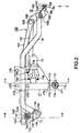
- the link mechanism 100 as shown in Fig. 2 comprises a rod 101 for conveying motive power, crank members 102 for converting the motive power, and a link ball joints 103 for connecting the rod 101 and the crank member 102.
- a first pivot shaft 104 and a second pivot shaft 105 are connected to the crank members 102, 102.
- the first pivot shaft 104 and the second pivot shaft 105 are rotatably attached to a first pivot holder 14 and a second pivot holder 15, respectively.
- the first pivot holder 14 and the second pivot holder 15 are respectively connected to both ends of a pipe 16 bent for passing over the wiper motor 13.
- a motor bracket (support member) 17 is attached to an upwardly bent section of the pipe 16. As described above, the motor bracket 17 supporting the first pivot holder 14, the second pivot holder 15 and the wiper motor 13 is integrated through the pipe 16, which means that the vehicle wiper assembly 1 has a modular structure with high rigidity.
- the wiper motor 13 is attached to a central section of the motor bracket 17 by using screws 13a, 13a, 13a.
- a motor bracket fixing section 17a for fixing to the vehicle body using a screw 171, a washer 172 and a rubber 173 is provided at a lower end of the motor bracket 17.
- An elliptical hole 17b is then formed between the wiper motor 13 and the motor bracket fixing section 17a. Both side sections of the elliptical hole 17b constitute low rupture strength weak points 17c, 17c.
- Another end of the motor bracket 17 constitutes a bearing section 17d for the pipe 16, and is rotatably attached to the pipe 16 by using nuts and bolts 170, 170, 170, 170.
- a first fixing section 14a for fixing to the vehicle body above the first pivot holder 14 by using a screw 141, a washer 142 and a rubber 143 is provided in the first pivot holder 14.
- An elliptical hole 14b is then formed between the first fixing section 14a and the first pivot shaft 104. Both side sections of this elliptical hole 14b constitute low rupture strength weak points 14c, 14c.
- a second fixing section 15 for fixing to the vehicle body by using a screw 151, a washer 152 and rubber 153 is provided on the second pivot holder 15, to the left side thereof.
- An elliptical hole 15b is formed between the second fixing section 15a and the second pivot shaft 105. The two sides of the elliptical hole 15b constitute low rupture strength weak points 15c, 15c.
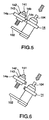
- the first pivot holder 14 when the external force is applied to the first pivot holder 14, as shown in Figs. 5 and 6, the first pivot holder 14 is detached by moving towards the inside direction of the vehicle due to the fact that the weak points 14c, 14c of the first pivot holder 14 are ruptured.
- the second pivot holder 15 when the external force is similarly applied to the second pivot holder 15, as shown in Figs. 7 and 8, the second pivot holder 15 is detached by moving towards the inside direction of the vehicle due to the fact that the weak points 15c, 15c of the second pivot holder 15 are ruptured.
- the vehicle wiper assembly 1 is completely detached by an external impact and it is possible to improve the overall impact absorbing performance of the vehicle wiper assembly 1.
- the weak points are formed by the elliptical holes, but the present invention is not thus limited, and it is possible to have the weak points formed as slots cut in from the sideward direction, or to have low rupture strength weak points formed by reducing the plate thickness.
Landscapes
- Engineering & Computer Science (AREA)
- Mechanical Engineering (AREA)
- Body Structure For Vehicles (AREA)
- Transmission Devices (AREA)
- Motor Or Generator Frames (AREA)
Abstract
Description
- The present invention relates to a vehicle wiper assembly.
- It has always been necessary, in a vehicle wiper assembly, to have technology for absorbing impacts from the outside. As one example of this, there is the technology disclosed in Japanese Patent Laid-open No. Hei. 11-34808. This technology is for absorbing the impacts from outside acting on a base and section of a wiper arm by rupturing or dropping off of a pivoted holder section.
- However, with the above described technology of the related art, only a pivoted holder section is made to drop off, and a wiper motor part for driving the wiper arm remains connected to the vehicle body. The wiper motor part is heavy and so has high rigidity, and in the event that external force from outside the vehicle is applied to the wiper motor part, it is not possible to absorb the impact. Particularly for a front wiper, as the wiper assembly thereof is housed in a bulkhead having a closed sectional form extending in a widthwise direction of the vehicle along a lower edge section of a front windshield, it is also commonly conventional for a wiper motor to be housed in the bulkhead. And further, for this type of structure, as a gap between the wiper motor and the bulkhead is reduced this causes a problem that it is difficult to absorb further impact.
- The purpose of the present invention is to enable sufficient absorption of the impact even when an external force from outside the vehicle is applied to the wiper motor part where there is a small gap between the wiper motor part of a wiper assembly and the bulkhead having high rigidity. The purpose of the present invention is also to improve an impact absorbing capability of the overall wiper assembly by causing the wiper assembly itself to also completely drop off due to external force from outside the vehicle, in addition to the impact absorption of the external force to the wiper motor section.
- In order to solve the problems described above, in a first aspect of the present invention, a vehicle wiper assembly is provided with a swingable wiper arm having a wiper blade for wiping a windshield attached to a tip end, and a wiper motor for driving the wiper arm, wherein the wiper motor is attached to move the wiper to the inside of the vehicle under an external force to the vehicle body.
- According to the first aspect of the present invention, since the wiper motor moves to the inside of the vehicle under the external force, the impact from outside can be absorbed by the wiper motor part.
- In a second aspect of the present invention, the wiper assembly is provided with a support member for attaching the wiper motor, and the support member is swingably attached at one end to the vehicle body and fixed at the other end, and is also provided with a weak point having low rupture strength in the vicinity of a vehicle body fixing section
- According to the second aspect of the present invention, since the wiper motor support member has the weak point with low rupture strength in the vicinity of the vehicle body fixing section, the weak point is ruptured if an external force is applied to the wiper motor section. And it is possible to absorb the impact by sliding the wiper motor support member to the inside of the vehicle.
- A third aspect of the present invention is to provide a support member to which the wiper motor is attached, and the support member has both ends fixed to the vehicle body, and has a weak point of the low rupture strength provided in the vicinity of a vehicle fixing section.
- According to the third aspect of the present invention, since the wiper motor support member has weak points of low rupture strength in the vicinity of the vehicle fixing section at the both ends, it is possible to absorb the impact through rupturing of the weak point by the external force and by detaching the wiper motor support member even if both ends of the wiper motor support member are fixed to the vehicle body.
- A fourth aspect of the present invention, has weak points having low rupture strength provided in the vicinity of vehicle fixing sections of pivot holders for rotatably supporting pivot shafts to attach base end sections of wiper arms.
- According to the fourth aspect of the present invention, since the pivot holders for the wiper arm shafts also have weak points of low rupture strength in the vicinity of the vehicle fixing sections, if the external force is applied to the pivot holder sections, the weak points of the pivot holders are ruptured, the pivot holder sections become detached, and the entire wiper assembly is detached. Accordingly, it is possible to improve the impact absorbing performance of the entire wiper assembly.
- By way of example only, a specific embodiment of the present invention will now be described, with reference to the accompanying drawings, in which:-
- FIG. 1 shows a first embodiment of a vehicle wiper assembly of the present invention.
- Fig. 2 is a schematic front elevation view of the vehicle wiper.
- Fig. 3 is a cross sectional view taken along line A -A in Fig. 2.
- Fig. 4 is a cross sectional drawing showing a motor bracket of Fig. 3 after rupture.
- Fig. 5 is the cross sectional view taken along line B - B in Fig. 2.
- Fig. 6 is the cross sectional drawing showing a first pivot holder of Fig. 5 after the rupture.
- Fig. 7 is a perspective view in the direction of arrow C in Fig. 2.
- Fig. 8 is a perspective view showing a second pivot holder of Fig. 7 after the rupture.
-
- An embodiment of the present invention will be described in detail in the following with reference to drawings.
- In the embodiment, a
wiper assembly 1, as shown in Fig. 1, is applied to a tandem type where a pair of left andright wiper arms 12 each with awiper blade 11 attached at a tip end swing together for wiping awindshield 2. Thewiper assembly 1 causes eachwiper arm 12 to swing by conveying motive power of awiper motor 13 through alink mechanism 100. - The
link mechanism 100, as shown in Fig. 2 comprises arod 101 for conveying motive power,crank members 102 for converting the motive power, and alink ball joints 103 for connecting therod 101 and thecrank member 102. Afirst pivot shaft 104 and asecond pivot shaft 105 are connected to thecrank members first pivot shaft 104 and thesecond pivot shaft 105 are rotatably attached to afirst pivot holder 14 and asecond pivot holder 15, respectively. Thefirst pivot holder 14 and thesecond pivot holder 15 are respectively connected to both ends of apipe 16 bent for passing over the wiper motor 13.A motor bracket (support member) 17 is attached to an upwardly bent section of thepipe 16.
As described above, themotor bracket 17 supporting thefirst pivot holder 14, thesecond pivot holder 15 and thewiper motor 13 is integrated through thepipe 16, which means that thevehicle wiper assembly 1 has a modular structure with high rigidity. - Next, the
motor bracket 17, thefirst pivot holder 14 and thesecond pivot holder 15 will be described in detail thereafter. - First of all, the
wiper motor 13 is attached to a central section of themotor bracket 17 by usingscrews bracket fixing section 17a for fixing to the vehicle body using ascrew 171, awasher 172 and arubber 173 is provided at a lower end of themotor bracket 17. Anelliptical hole 17b is then formed between thewiper motor 13 and the motorbracket fixing section 17a. Both side sections of theelliptical hole 17b constitute low rupture strengthweak points motor bracket 17 constitutes abearing section 17d for thepipe 16, and is rotatably attached to thepipe 16 by using nuts andbolts - Also, a
first fixing section 14a for fixing to the vehicle body above thefirst pivot holder 14 by using ascrew 141, awasher 142 and arubber 143 is provided in thefirst pivot holder 14. Anelliptical hole 14b is then formed between thefirst fixing section 14a and thefirst pivot shaft 104. Both side sections of thiselliptical hole 14b constitute low rupture strengthweak points second fixing section 15 for fixing to the vehicle body by using ascrew 151, a washer 152 andrubber 153 is provided on thesecond pivot holder 15, to the left side thereof. Anelliptical hole 15b is formed between thesecond fixing section 15a and thesecond pivot shaft 105. The two sides of theelliptical hole 15b constitute low rupture strengthweak points - Next, an operation will be described when an external force is applied to sections including the
vehicle wiper assembly 1. - First, when the external force is applied to the
wiper motor 13 part, as shown in Figs. 3 and 4, due to the fact that theweak points motor bracket 17 are ruptured, themotor bracket 17 rotates towards the inside direction of the vehicle body and is detached. Also, thewiper motor 13 is detached due to the fact that it rotates inside a narrow space formed by a vehicle body panel shown by the dotted line in the drawing. - Also, when the external force is applied to the
first pivot holder 14, as shown in Figs. 5 and 6, thefirst pivot holder 14 is detached by moving towards the inside direction of the vehicle due to the fact that theweak points first pivot holder 14 are ruptured. On the other hand, when the external force is similarly applied to thesecond pivot holder 15, as shown in Figs. 7 and 8, thesecond pivot holder 15 is detached by moving towards the inside direction of the vehicle due to the fact that theweak points second pivot holder 15 are ruptured. - Accordingly, with the embodiment described above, if the external force is applied to the
wiper motor 13, since theweak points motor bracket 17 are ruptured and themotor bracket 17 is detached by rotating towards the inside direction of the vehicle, it is possible to absorb the impact at thewiper motor 13. - Due to the fact that the
first pivot holder 14 and thesecond pivot holder 15 are also detached as well as themotor bracket 17, thevehicle wiper assembly 1 is completely detached by an external impact and it is possible to improve the overall impact absorbing performance of thevehicle wiper assembly 1. - In the embodiment described above, the weak points are formed by the elliptical holes, but the present invention is not thus limited, and it is possible to have the weak points formed as slots cut in from the sideward direction, or to have low rupture strength weak points formed by reducing the plate thickness.
- It is also possible to have a structure where both ends of the motor bracket are fixed to the vehicle body, with the low rupture strength weak points provided in the vicinity of the vehicle body fixing sections, so that the motor bracket is detached by the external force.
- While the presently preffered embodiments of the present invention have been shown and described, it is to be understood that these disclosures are for the purpose of illustration and that various changes and modifications may be made without departing from the scope of the invention as set forth in the appended claims.
Claims (4)
- A vehicle wiper assembly (1) having a swingable wiper arm (12) provided in the vicinity of a windshield (2) and a wiper blade (11) attached to a tip end of said wiper arm for wiping said windshield, comprising:a wiper motor (13) for driving said wiper arm (12); andsaid wiper motor (13) is attached to a vehicle body so as to move inside the vehicle body by an external force.
- The vehicle wiper assembly according to claim 1, further comprising:a first support member (17) swingably attached to the vehicle body at one end and fixed to the vehicle body at the other end; anda first weak point (17c) having low rupture strength provided in the vicinity of a vehicle fixing section (17a).
- The vehicle wiper assembly according to claim 1 or claim 2, further comprising:a second support member (16) fixed to the vehicle body at both ends, and a second weak point (14c, 15c) having low rupture strength provided in the vicinity of said vehicle fixing section (14a, 15a).
- The vehicle wiper assembly of claim 2 or claim 3, wherein each of said first weak point (17c) and said second weak point (14c, 15c) having low rupture strength is provided in the vicinity of a vehicle fixing section (14a, 15a) of a pivot holder (14, 15) for rotatably supporting a pivot shaft (104, 105) for attaching a base end section of the wiper arm (12).
Applications Claiming Priority (2)
| Application Number | Priority Date | Filing Date | Title |
|---|---|---|---|
| JP2000402377 | 2000-12-28 | ||
| JP2000402377A JP4708560B2 (en) | 2000-12-28 | 2000-12-28 | Vehicle wiper device |
Publications (3)
| Publication Number | Publication Date |
|---|---|
| EP1219513A2 true EP1219513A2 (en) | 2002-07-03 |
| EP1219513A3 EP1219513A3 (en) | 2003-12-17 |
| EP1219513B1 EP1219513B1 (en) | 2008-03-05 |
Family
ID=18866685
Family Applications (1)
| Application Number | Title | Priority Date | Filing Date |
|---|---|---|---|
| EP01310858A Expired - Lifetime EP1219513B1 (en) | 2000-12-28 | 2001-12-22 | Wiper assembly for vehicle |
Country Status (4)
| Country | Link |
|---|---|
| US (1) | US6854154B2 (en) |
| EP (1) | EP1219513B1 (en) |
| JP (1) | JP4708560B2 (en) |
| DE (1) | DE60133080T2 (en) |
Cited By (10)
| Publication number | Priority date | Publication date | Assignee | Title |
|---|---|---|---|---|
| EP1346903A3 (en) * | 2002-03-20 | 2004-06-02 | Nissan Motor Company, Limited | Cowl structure for a vehicle |
| FR2850922A1 (en) * | 2003-02-10 | 2004-08-13 | Bosch Gmbh Robert | Windshield wiper drive fixing equipment for vehicle, has support wall segment with lesser rigidity in its deformation zone near fixing points than at rest of support wall |
| FR2855473A1 (en) * | 2003-05-28 | 2004-12-03 | Peugeot Citroen Automobiles Sa | Vehicle wind shield wiper mechanism positioning and fixing device, has three male and female fixation units forming connection by elastic interlocking along common axis, where bearing blocks with rigid support forms female units |
| WO2005080158A1 (en) * | 2004-02-20 | 2005-09-01 | Robert Bosch Gmbh | Windshield wiping device |
| EP1607292A1 (en) * | 2004-06-18 | 2005-12-21 | Glaverbel | Glazing and windscreen wiper assembly |
| FR2877299A1 (en) * | 2004-11-04 | 2006-05-05 | Renault Sas | WIPER DEVICE FOR VEHICLE |
| FR2906776A1 (en) * | 2006-10-09 | 2008-04-11 | Peugeot Citroen Automobiles Sa | Windscreen wiper assembly arranging device for motor vehicle, has support unit with connection elements connected with body, where elements are deformed according to respective lines when pedestrian head dashes part of driving pin of brush |
| EP1720746B1 (en) * | 2004-02-26 | 2008-09-03 | Robert Bosch Gmbh | Windshield wiping device, especially for a motor vehicle |
| DE102010062495A1 (en) | 2010-12-07 | 2012-06-14 | Robert Bosch Gmbh | Windshield wiper device |
| FR3016588A1 (en) * | 2014-01-21 | 2015-07-24 | Peugeot Citroen Automobiles Sa | LOW WEAR SUPPORT PLATE FOR A WIPER ARM DRIVE DEVICE OF A VEHICLE GLASS |
Families Citing this family (27)
| Publication number | Priority date | Publication date | Assignee | Title |
|---|---|---|---|---|
| US6845540B1 (en) | 2002-04-30 | 2005-01-25 | Valeo Electrical Systems, Inc. | Wiper pivot housing with spring release pivot shaft |
| US6701569B1 (en) * | 2002-04-30 | 2004-03-09 | Valeo Electrical Systems, Inc. | Wiper pivot housing with frangible mount |
| US20040101359A1 (en) * | 2002-11-27 | 2004-05-27 | Gottorff Richard L. | Hybrid plug-n-play module attachment |
| US7191487B2 (en) | 2002-12-30 | 2007-03-20 | Valeo Electrical Systems, Inc. | Vehicle wiper apparatus with energy absorption collapsible pivot shaft |
| US7185390B2 (en) * | 2002-12-30 | 2007-03-06 | Valeo Electrical Systems, Inc. | Energy absorbing pedestrian safety feature for vehicle wiper pivot apparatus |
| JP4089473B2 (en) | 2003-03-12 | 2008-05-28 | 株式会社ジェイテクト | Reservoir tank with integrated bracket |
| DE10327858A1 (en) | 2003-06-18 | 2005-01-05 | Robert Bosch Gmbh | Windscreen wiper device, in particular for a motor vehicle |
| JP4141361B2 (en) * | 2003-09-26 | 2008-08-27 | アスモ株式会社 | Vehicle front structure |
| JP4146329B2 (en) * | 2003-11-11 | 2008-09-10 | アスモ株式会社 | Vehicle wiper device |
| JP4200506B2 (en) * | 2006-10-27 | 2008-12-24 | いすゞ自動車株式会社 | In-vehicle component mounting structure |
| JP4950925B2 (en) * | 2008-03-21 | 2012-06-13 | 株式会社ミツバ | Wiper device |
| DE102009057589B4 (en) * | 2008-12-11 | 2017-02-02 | Asmo Co., Ltd. | wiper device |
| JP2010285115A (en) * | 2009-06-12 | 2010-12-24 | Kanto Auto Works Ltd | Wiper pivot structure |
| US8917828B2 (en) | 2010-04-21 | 2014-12-23 | Angel.Com Incorporated | Multi-channel delivery platform |
| US8699674B2 (en) | 2010-04-21 | 2014-04-15 | Angel.Com Incorporated | Dynamic speech resource allocation |
| US8582727B2 (en) | 2010-04-21 | 2013-11-12 | Angel.Com | Communication of information during a call |
| WO2012071190A2 (en) * | 2010-11-22 | 2012-05-31 | Bae Systems Land & Armaments L.P. | Break-away wiper extension for vee windows |
| DE102011085163A1 (en) * | 2011-10-25 | 2013-04-25 | Bombardier Transportation Gmbh | Front arrangement for a vehicle, in particular for a rail vehicle, with a windscreen cleaning device |
| DE102011090155A1 (en) * | 2011-12-30 | 2013-07-04 | Robert Bosch Gmbh | Carrier element for a wiper drive |
| JP2014141208A (en) * | 2013-01-25 | 2014-08-07 | Nissan Motor Co Ltd | Fitting structure for wiper bracket |
| US20140250622A1 (en) * | 2013-03-08 | 2014-09-11 | Mitsuba Corporation | Windshield wiper assembly |
| US9285974B2 (en) | 2014-02-28 | 2016-03-15 | Angel.Com Incorporated | Application builder platform |
| US9571636B2 (en) | 2014-12-31 | 2017-02-14 | Genesys Telecommunications Laboratories, Inc. | Call center builder platform |
| WO2017043324A1 (en) * | 2015-09-08 | 2017-03-16 | アスモ 株式会社 | Wiper device |
| US9944300B2 (en) * | 2015-12-28 | 2018-04-17 | Kawasaki Iukogyo Kabushiki Kaisha | Railcar with end cap |
| BR102022009070A2 (en) * | 2022-05-10 | 2023-11-21 | Valeo Systemes D'essuyage | SUPPORT DEVICE FOR A WINDSHIELD WIPER MOUNTING ASSEMBLY |
| FR3150760B1 (en) * | 2023-07-04 | 2025-05-30 | Psa Automobiles Sa | Wiping system for a glass wall of a motor vehicle |
Citations (1)
| Publication number | Priority date | Publication date | Assignee | Title |
|---|---|---|---|---|
| JPH1134808A (en) | 1997-07-24 | 1999-02-09 | Honda Motor Co Ltd | Vehicle wiper device |
Family Cites Families (12)
| Publication number | Priority date | Publication date | Assignee | Title |
|---|---|---|---|---|
| DE4446315A1 (en) * | 1994-12-23 | 1996-06-27 | Teves Gmbh Alfred | Windscreen wiper system with a noise or vibration damping fastener |
| FR2733474B1 (en) * | 1995-04-28 | 1997-06-06 | Valeo Systemes Dessuyage | WIPER DEVICE FOR A MOTOR VEHICLE COMPRISING A FIXING PLATE WITH BREAKING PRIMER, AND PLATE BELONGING TO SUCH A DEVICE |
| JP2994584B2 (en) * | 1995-12-26 | 1999-12-27 | アスモ株式会社 | Modular wiper device |
| DE69828368T2 (en) * | 1997-10-22 | 2005-12-08 | Nissan Motor Co., Ltd., Yokohama | Wiper device for motor vehicles |
| JP3385196B2 (en) * | 1997-11-11 | 2003-03-10 | 自動車電機工業株式会社 | Automotive wiper |
| JPH11189130A (en) * | 1997-12-25 | 1999-07-13 | Suzuki Motor Corp | Wiper pivot |
| FR2775456B1 (en) * | 1998-02-27 | 2000-05-12 | Valeo Systemes Dessuyage | WIPER DEVICE FOR A MOTOR VEHICLE COMPRISING A FIXING PLATE WHICH MAY BE ERASED IN THE EVENT OF IMPACT, AND A PLATINY BELONGING TO SUCH A DEVICE |
| JP3449463B2 (en) * | 1998-05-12 | 2003-09-22 | 本田技研工業株式会社 | Windshield support structure |
| JP3563285B2 (en) * | 1999-02-12 | 2004-09-08 | ダイハツ工業株式会社 | Motor unit mounting structure for vehicle wiper device |
| JP4406478B2 (en) * | 1999-02-25 | 2010-01-27 | アスモ株式会社 | Motor mounting structure |
| JP2000326829A (en) * | 1999-05-17 | 2000-11-28 | Mitsubishi Motors Corp | Wiper mounting structure |
| JP4081216B2 (en) * | 2000-02-04 | 2008-04-23 | 株式会社ミツバ | Wiper pivot |
-
2000
- 2000-12-28 JP JP2000402377A patent/JP4708560B2/en not_active Expired - Lifetime
-
2001
- 2001-12-22 EP EP01310858A patent/EP1219513B1/en not_active Expired - Lifetime
- 2001-12-22 DE DE60133080T patent/DE60133080T2/en not_active Expired - Lifetime
- 2001-12-28 US US10/028,713 patent/US6854154B2/en not_active Expired - Lifetime
Patent Citations (1)
| Publication number | Priority date | Publication date | Assignee | Title |
|---|---|---|---|---|
| JPH1134808A (en) | 1997-07-24 | 1999-02-09 | Honda Motor Co Ltd | Vehicle wiper device |
Cited By (16)
| Publication number | Priority date | Publication date | Assignee | Title |
|---|---|---|---|---|
| US6869134B2 (en) | 2002-03-20 | 2005-03-22 | Nissan Motor Co., Ltd. | Cowl structure for a vehicle |
| EP1346903A3 (en) * | 2002-03-20 | 2004-06-02 | Nissan Motor Company, Limited | Cowl structure for a vehicle |
| FR2850922A1 (en) * | 2003-02-10 | 2004-08-13 | Bosch Gmbh Robert | Windshield wiper drive fixing equipment for vehicle, has support wall segment with lesser rigidity in its deformation zone near fixing points than at rest of support wall |
| FR2855473A1 (en) * | 2003-05-28 | 2004-12-03 | Peugeot Citroen Automobiles Sa | Vehicle wind shield wiper mechanism positioning and fixing device, has three male and female fixation units forming connection by elastic interlocking along common axis, where bearing blocks with rigid support forms female units |
| US7891043B2 (en) | 2004-02-20 | 2011-02-22 | Robert Bosch Gmbh | Winshield wiping device |
| WO2005080158A1 (en) * | 2004-02-20 | 2005-09-01 | Robert Bosch Gmbh | Windshield wiping device |
| US8370988B2 (en) | 2004-02-26 | 2013-02-12 | Robert Bosch Gmbh | Windshield wiping device, especially for a motor vehicle |
| EP1720746B1 (en) * | 2004-02-26 | 2008-09-03 | Robert Bosch Gmbh | Windshield wiping device, especially for a motor vehicle |
| EP1607292A1 (en) * | 2004-06-18 | 2005-12-21 | Glaverbel | Glazing and windscreen wiper assembly |
| FR2877299A1 (en) * | 2004-11-04 | 2006-05-05 | Renault Sas | WIPER DEVICE FOR VEHICLE |
| WO2006048582A1 (en) * | 2004-11-04 | 2006-05-11 | Renault S.A.S. | Windscreen wiper device for vehicle |
| FR2906776A1 (en) * | 2006-10-09 | 2008-04-11 | Peugeot Citroen Automobiles Sa | Windscreen wiper assembly arranging device for motor vehicle, has support unit with connection elements connected with body, where elements are deformed according to respective lines when pedestrian head dashes part of driving pin of brush |
| EP1911640A1 (en) * | 2006-10-09 | 2008-04-16 | Peugeot Citroën Automobiles S.A. | Device for arranging an automobile windscreen wiper assembly |
| DE102010062495A1 (en) | 2010-12-07 | 2012-06-14 | Robert Bosch Gmbh | Windshield wiper device |
| WO2012076312A1 (en) | 2010-12-07 | 2012-06-14 | Robert Bosch Gmbh | Window wiper device |
| FR3016588A1 (en) * | 2014-01-21 | 2015-07-24 | Peugeot Citroen Automobiles Sa | LOW WEAR SUPPORT PLATE FOR A WIPER ARM DRIVE DEVICE OF A VEHICLE GLASS |
Also Published As
| Publication number | Publication date |
|---|---|
| JP4708560B2 (en) | 2011-06-22 |
| DE60133080D1 (en) | 2008-04-17 |
| JP2002200969A (en) | 2002-07-16 |
| US6854154B2 (en) | 2005-02-15 |
| EP1219513B1 (en) | 2008-03-05 |
| DE60133080T2 (en) | 2009-02-26 |
| EP1219513A3 (en) | 2003-12-17 |
| US20020083544A1 (en) | 2002-07-04 |
Similar Documents
| Publication | Publication Date | Title |
|---|---|---|
| US6854154B2 (en) | Wiper assembly with movable wiper motor support | |
| BRPI0617185A2 (en) | windshield wiper arm | |
| US8122559B2 (en) | Wiper system for vehicle | |
| US20020002755A1 (en) | Articulation system between windscreen wiper components | |
| KR970706149A (en) | QUADRUPLE-JOINT WIPER ARM FOR WINDSCREEN WIPER SYSTEM OF A MOTOR VEHICLE FOR WIPER SYSTEM OF AUTOMOTIVE WINDOWS | |
| US6651291B2 (en) | Wiper assembly capable of adjusting a wiping angle | |
| US8209813B2 (en) | Vehicle windshield wiper system | |
| JP3342779B2 (en) | Mounting structure of wind receiver in wiper device | |
| JP2000326829A (en) | Wiper mounting structure | |
| JP3218003B2 (en) | Wiper device | |
| JP4136311B2 (en) | Four-bar wiper arm for window glass wiper device | |
| CN216424346U (en) | Windscreen wiper fixing device, windscreen wiper and operation machine | |
| JP3759331B2 (en) | Car wiper | |
| JP6172962B2 (en) | Wiper device | |
| US20060070200A1 (en) | Wiper device attached using plate-shaped lever or lever having a bent portion | |
| JP4141227B2 (en) | Vehicle wiper device | |
| JP2000052938A (en) | Wiper device | |
| CN222591630U (en) | Swing opening and closing mechanism, vehicle spoiler and vehicle | |
| JP4630290B2 (en) | Vehicle with windshield wiper device | |
| JP3764054B2 (en) | Wiper device | |
| JPH06227444A (en) | Front spoiler device | |
| CN223919423U (en) | Tail wing device and vehicle | |
| KR100368925B1 (en) | Wiper device for use in an automobile | |
| KR20010001913U (en) | Wind shield wiper for vehicles | |
| KR200213440Y1 (en) | Mounting bracket for a pivot housing of wiper system |
Legal Events
| Date | Code | Title | Description |
|---|---|---|---|
| PUAI | Public reference made under article 153(3) epc to a published international application that has entered the european phase |
Free format text: ORIGINAL CODE: 0009012 |
|
| AK | Designated contracting states |
Kind code of ref document: A2 Designated state(s): AT BE CH CY DE DK ES FI FR GB GR IE IT LI LU MC NL PT SE TR |
|
| AX | Request for extension of the european patent |
Free format text: AL;LT;LV;MK;RO;SI |
|
| PUAL | Search report despatched |
Free format text: ORIGINAL CODE: 0009013 |
|
| AK | Designated contracting states |
Kind code of ref document: A3 Designated state(s): AT BE CH CY DE DK ES FI FR GB GR IE IT LI LU MC NL PT SE TR |
|
| AX | Request for extension of the european patent |
Extension state: AL LT LV MK RO SI |
|
| 17P | Request for examination filed |
Effective date: 20040223 |
|
| 17Q | First examination report despatched |
Effective date: 20040401 |
|
| AKX | Designation fees paid |
Designated state(s): DE FR GB |
|
| GRAP | Despatch of communication of intention to grant a patent |
Free format text: ORIGINAL CODE: EPIDOSNIGR1 |
|
| GRAS | Grant fee paid |
Free format text: ORIGINAL CODE: EPIDOSNIGR3 |
|
| GRAA | (expected) grant |
Free format text: ORIGINAL CODE: 0009210 |
|
| AK | Designated contracting states |
Kind code of ref document: B1 Designated state(s): DE FR GB |
|
| REG | Reference to a national code |
Ref country code: GB Ref legal event code: FG4D |
|
| REF | Corresponds to: |
Ref document number: 60133080 Country of ref document: DE Date of ref document: 20080417 Kind code of ref document: P |
|
| EN | Fr: translation not filed | ||
| PLBE | No opposition filed within time limit |
Free format text: ORIGINAL CODE: 0009261 |
|
| STAA | Information on the status of an ep patent application or granted ep patent |
Free format text: STATUS: NO OPPOSITION FILED WITHIN TIME LIMIT |
|
| 26N | No opposition filed |
Effective date: 20081208 |
|
| PG25 | Lapsed in a contracting state [announced via postgrant information from national office to epo] |
Ref country code: FR Free format text: LAPSE BECAUSE OF FAILURE TO SUBMIT A TRANSLATION OF THE DESCRIPTION OR TO PAY THE FEE WITHIN THE PRESCRIBED TIME-LIMIT Effective date: 20081226 |
|
| GBPC | Gb: european patent ceased through non-payment of renewal fee |
Effective date: 20081222 |
|
| PG25 | Lapsed in a contracting state [announced via postgrant information from national office to epo] |
Ref country code: GB Free format text: LAPSE BECAUSE OF NON-PAYMENT OF DUE FEES Effective date: 20081222 |
|
| REG | Reference to a national code |
Ref country code: DE Ref legal event code: R082 Ref document number: 60133080 Country of ref document: DE Representative=s name: VOSSIUS & PARTNER PATENTANWAELTE RECHTSANWAELT, DE Ref country code: DE Ref legal event code: R081 Ref document number: 60133080 Country of ref document: DE Owner name: SUBARU CORPORATION, JP Free format text: FORMER OWNER: FUJI JUKOGYO K.K., TOKIO/TOKYO, JP |
|
| PGFP | Annual fee paid to national office [announced via postgrant information from national office to epo] |
Ref country code: DE Payment date: 20181210 Year of fee payment: 18 |
|
| REG | Reference to a national code |
Ref country code: DE Ref legal event code: R119 Ref document number: 60133080 Country of ref document: DE |
|
| PG25 | Lapsed in a contracting state [announced via postgrant information from national office to epo] |
Ref country code: DE Free format text: LAPSE BECAUSE OF NON-PAYMENT OF DUE FEES Effective date: 20200701 |