EP1219431A2 - Méthode et appareil d'impression à jet d'encre continu à masquage de goutte - Google Patents
Méthode et appareil d'impression à jet d'encre continu à masquage de goutte Download PDFInfo
- Publication number
- EP1219431A2 EP1219431A2 EP01204938A EP01204938A EP1219431A2 EP 1219431 A2 EP1219431 A2 EP 1219431A2 EP 01204938 A EP01204938 A EP 01204938A EP 01204938 A EP01204938 A EP 01204938A EP 1219431 A2 EP1219431 A2 EP 1219431A2
- Authority
- EP
- European Patent Office
- Prior art keywords
- ink
- flow path
- droplets
- streams
- ink droplets
- Prior art date
- Legal status (The legal status is an assumption and is not a legal conclusion. Google has not performed a legal analysis and makes no representation as to the accuracy of the status listed.)
- Granted
Links
Images


Classifications
-
- B—PERFORMING OPERATIONS; TRANSPORTING
- B41—PRINTING; LINING MACHINES; TYPEWRITERS; STAMPS
- B41J—TYPEWRITERS; SELECTIVE PRINTING MECHANISMS, i.e. MECHANISMS PRINTING OTHERWISE THAN FROM A FORME; CORRECTION OF TYPOGRAPHICAL ERRORS
- B41J2/00—Typewriters or selective printing mechanisms characterised by the printing or marking process for which they are designed
- B41J2/005—Typewriters or selective printing mechanisms characterised by the printing or marking process for which they are designed characterised by bringing liquid or particles selectively into contact with a printing material
- B41J2/01—Ink jet
- B41J2/015—Ink jet characterised by the jet generation process
- B41J2/02—Ink jet characterised by the jet generation process generating a continuous ink jet
- B41J2/03—Ink jet characterised by the jet generation process generating a continuous ink jet by pressure
-
- B—PERFORMING OPERATIONS; TRANSPORTING
- B41—PRINTING; LINING MACHINES; TYPEWRITERS; STAMPS
- B41J—TYPEWRITERS; SELECTIVE PRINTING MECHANISMS, i.e. MECHANISMS PRINTING OTHERWISE THAN FROM A FORME; CORRECTION OF TYPOGRAPHICAL ERRORS
- B41J2/00—Typewriters or selective printing mechanisms characterised by the printing or marking process for which they are designed
- B41J2/005—Typewriters or selective printing mechanisms characterised by the printing or marking process for which they are designed characterised by bringing liquid or particles selectively into contact with a printing material
- B41J2/01—Ink jet
- B41J2/07—Ink jet characterised by jet control
- B41J2/075—Ink jet characterised by jet control for many-valued deflection
- B41J2/08—Ink jet characterised by jet control for many-valued deflection charge-control type
- B41J2/09—Deflection means
-
- B—PERFORMING OPERATIONS; TRANSPORTING
- B41—PRINTING; LINING MACHINES; TYPEWRITERS; STAMPS
- B41J—TYPEWRITERS; SELECTIVE PRINTING MECHANISMS, i.e. MECHANISMS PRINTING OTHERWISE THAN FROM A FORME; CORRECTION OF TYPOGRAPHICAL ERRORS
- B41J2/00—Typewriters or selective printing mechanisms characterised by the printing or marking process for which they are designed
- B41J2/005—Typewriters or selective printing mechanisms characterised by the printing or marking process for which they are designed characterised by bringing liquid or particles selectively into contact with a printing material
- B41J2/01—Ink jet
- B41J2/015—Ink jet characterised by the jet generation process
- B41J2/02—Ink jet characterised by the jet generation process generating a continuous ink jet
- B41J2002/022—Control methods or devices for continuous ink jet
-
- B—PERFORMING OPERATIONS; TRANSPORTING
- B41—PRINTING; LINING MACHINES; TYPEWRITERS; STAMPS
- B41J—TYPEWRITERS; SELECTIVE PRINTING MECHANISMS, i.e. MECHANISMS PRINTING OTHERWISE THAN FROM A FORME; CORRECTION OF TYPOGRAPHICAL ERRORS
- B41J2/00—Typewriters or selective printing mechanisms characterised by the printing or marking process for which they are designed
- B41J2/005—Typewriters or selective printing mechanisms characterised by the printing or marking process for which they are designed characterised by bringing liquid or particles selectively into contact with a printing material
- B41J2/01—Ink jet
- B41J2/015—Ink jet characterised by the jet generation process
- B41J2/02—Ink jet characterised by the jet generation process generating a continuous ink jet
- B41J2/03—Ink jet characterised by the jet generation process generating a continuous ink jet by pressure
- B41J2002/032—Deflection by heater around the nozzle
-
- B—PERFORMING OPERATIONS; TRANSPORTING
- B41—PRINTING; LINING MACHINES; TYPEWRITERS; STAMPS
- B41J—TYPEWRITERS; SELECTIVE PRINTING MECHANISMS, i.e. MECHANISMS PRINTING OTHERWISE THAN FROM A FORME; CORRECTION OF TYPOGRAPHICAL ERRORS
- B41J2/00—Typewriters or selective printing mechanisms characterised by the printing or marking process for which they are designed
- B41J2/005—Typewriters or selective printing mechanisms characterised by the printing or marking process for which they are designed characterised by bringing liquid or particles selectively into contact with a printing material
- B41J2/01—Ink jet
- B41J2/015—Ink jet characterised by the jet generation process
- B41J2/02—Ink jet characterised by the jet generation process generating a continuous ink jet
- B41J2/03—Ink jet characterised by the jet generation process generating a continuous ink jet by pressure
- B41J2002/033—Continuous stream with droplets of different sizes
Definitions
- This invention generally relates to a method and apparatus for continuous inkjet printing, and more particularly to a continuous inkjet printing method wherein a first stream of ink droplets traveling along a first flow path is used as a mask by colliding with a second stream of ink droplets traveling along a second, intersecting flow path in route to a receiver on which an image is to be printed, selected droplets of the second droplet stream being timed to pass between and avoid the masking droplets so as to travel on and impinge the receiver for forming the image thereon.
- An inkjet printer produces images on a receiver by ejecting ink droplets onto the receiver in an image-wise fashion.
- the advantages of non-impact, low-noise, low energy use, and low cost operation in addition to the capability of the printer to print on plain paper are largely responsible for the wide acceptance of inkjet printers in the marketplace.
- Inkjet printing mechanisms can be categorized as either Drop-on-Demand or continuous inkjet. Continuous inkjet printing dates back to at least 1929. See U.S. Patent No. 1,941,001 to Hansell.
- the term "Drop-on-Demand” characterizes inkjet printers, wherein at every orifice a pressurization actuator is used to produce the inkjet droplet.
- a pressurization actuator is used to produce the inkjet droplet.
- either one of two types of actuators may be used. These two types of actuators are heat actuators and piezoelectric actuators.
- heat actuators With respect to heat actuators, a heater placed at a convenient location heats the ink and a quantity of the ink will phase change into a gaseous steam bubble and raise the internal ink pressure sufficiently for an ink droplet to be expelled to the recording medium.
- a feature of the heat-type actuators is the ability to incorporate them easily into modem known print head constructions, particularly those using silicon substrates with CMOS electrical circuitry.
- piezoelectric actuators a piezoelectric material is used, which piezoelectric material possesses piezoelectric properties such that a mechanical stress is produced when an electric field is applied.
- the most common of the "continuous" inkjet printers utilize electrostatic charging tunnels that are placed close to the point where ink droplets are being ejected in the form of a stream. Selected ones of the droplets are electrically charged by the charging tunnels. The charged droplets are deflected downstream by the presence of deflector plates that have a predetermined electric potential difference between them. A gutter may be used to intercept the charged droplets, while the uncharged droplets are free to strike the recording medium.
- a disadvantage of the known continuous inkjet printers is that the charging apparatus is complex and costly to incorporate into the print head. In addition, the interaction between charged drops can adversely affect image quality.
- a novel continuous inkjet printer is described and claimed in U.S. Patent 6,079,821, issued to Chwalek et al. on June 27, 2000, and assigned to the Eastman Kodak Company. Such printers use asymmetric heating in lieu of electrostatic charging tunnels to deflect ink droplets toward desired locations on the recording medium.
- a droplet generator formed from a heater having a selectively-actuated section associated with only a portion of the nozzle bore perimeter is provided for each of the ink nozzle bores. Periodic actuation of the heater element via a train of uniform electrical power pulses creates an asymmetric application of heat to the stream of droplets to control the direction of the stream between a print direction and a non-print direction.
- An object of the present invention is to provide a continuous inkjet printing method and apparatus which utilizes desirable aspects of "on-demand” printing and “masking” concepts without including the undesirable aspects of their respective printing apparatus.
- the present invention resides in an inkjet printing method comprising the steps of (1) generating a first stream of ink droplets traveling along a first flow path, and (2) generating a second stream of ink droplets traveling along a second flow path which intersects the first flow path at a predetermined location.
- the second stream of ink droplets includes ink droplets traveling in timed relation to the droplets of the first stream so as to collide with the droplets of the first stream at the predetermined location and be diverted to an ink receptacle.
- the second stream of ink droplets also includes selected droplets traveling in timed relation to the droplets of the first stream so as to pass between the droplets of the first stream at the predetermined location and continue along the second flow path so as to impinge a receiver at a down stream location along the second flow path for forming an image on the receiver.
- an inkjet printer comprising an element for emitting a first ink stream along a first flow path; an element located along the first flow path upstream of the predetermined location for controllably breaking the first ink stream into successive ink droplets traveling along the first flow path; an element for emitting a second ink stream along a second flow path which intersects the first flow path at a predetermined location; an element located along the second flow path upstream of the predetermined location for controllably breaking the second ink stream into successive ink droplets traveling along the second flow path; and an element for controlling the time relationship of droplet formation between the ink streams such that selected ink droplets of the first stream will pass between or collide with the ink droplets of the second stream at the predetermined intersection location in an image-wise manner.
- the droplets moving along the first path impinge on an image receiver located beyond the predetermined jet-crossing location.
- Another feature of the present invention is the provision of an element for controllably generating a stream of ink droplets by intermittently effecting surface tension and viscosity changes in a continuous stream of ink.
- Another feature of the present invention is the provision of two streams of ink droplets traveling along intersecting flow paths, wherein one of the streams of ink droplets includes selected droplets timed to pass between the droplets of another of the streams so as to travel on and impinge a receiver for forming an image thereon.
- Another feature of the present invention is the provision of an element for controllably breaking a stream of ink into a succession of ink droplets traveling in timed relations to one another along a flow path.
- Another feature of the present invention is the provision of streams of ink droplets generated by transiently heating continuous streams of ink to break the streams into the droplets, wherein larger ink droplets are generated by longer time intervals between the heat pulses and smaller ink droplets are generated by shorter intervals between the heat pulses.
- An advantage of the present invention is the capability to selectively mask a stream of ink droplets without requiring droplet electrical polarization.
- Another advantage of the present invention is the capability to generate different size ink droplets from a single continuous ink stream.
- Still another advantage of the present invention is the ability to provide a drop-masking continuous ink jet printing method that is compatible with a low voltage print head system.
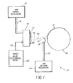
- apparatus 10 for drop-masking continuous inkjet printing constructed and operable according to the teachings of the present invention.
- Apparatus 10 is shown in association with a receiver 12 onto which an image is to be formed by apparatus 10, which receiver 12 can comprise any suitable conventional recording medium, such as a sheet of paper, a transparent film or the like.
- Apparatus 10 includes a print head 14, an ink supply reservoir 16 connected to print head 14 by an ink supply channel 18 for supplying ink thereto, a print head electrical drive 20 connected to print head 14 by a conductive path 22 for communicating electrical drive signals to print head 14 for controllably operating print head 14, an ink gutter 24 disposed between receiver 12 and print head 14 connected to an ink return reservoir 26 via an ink return conduit 28, and a rotatable drum 30 for holding and moving receiver 12 relative to print head 14 during the printing operation.
- print head 14 includes a nozzle plate 32 including a plurality of pairs of ink ejecting nozzles 34 and 36 having orifices 38 and 40, respectively, communicating with at least one ink chamber 42 connected in fluid communication with ink supply reservoir 16 via an ink supply channel 18 in a conventional and well known manner.
- Ink within ink chamber 42 is emitted from print head 14 through orifices 38 and 40 of ink ejecting nozzles 34 and 36 in continuous ink streams 44 and 46, respectively, under pressure generated using a suitable conventional device such as a pump or the like (not shown).
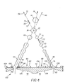
- Ink stream 44 is emitted along a flow path 48, and has a cross-sectional extent as denoted at 50 and an angular orientation as denoted at 52 relative to a front surface 54 of nozzle plate 32 which are determined by the size of orifice 38 and angle thereof relative to front surface 54.
- ink stream 46 is emitted from orifice 40 along a flow path 56, and has a cross-sectional extent 58 and an angular orientation 60 relative to front surface 54 which are determined by the cross-sectionals extent of orifice 40 and angular orientation thereof relative to front surface 54.
- Flow path 48 and flow path 56 are oriented with respect to one another so as to intersect at a predetermined location 62 spaced from front surface 54 of nozzle plate 32.
- Print head 14 includes an element 64 operable for controllably breaking ink stream 44 into successive ink droplets flowing along flow path 48, represented by ink droplet 66, upstream of predetermined location 62.
- print head 14 includes an element 68 operable for controllably breaking ink stream 46 into ink droplets flowing along flow path 56, represented by ink droplets 70 and 72, upstream of location 62.
- ink droplets 66, 70 and 72 collide with ink droplets 70 traveling along flow path 56 at location 62, to thereby "mask" the affected ink drops 70, that is, prevent their continued passage along flow path 56 past location 62 while permitting ink droplets 72 to proceed along flow path 56.
- drum 30 is positioned in spaced relation to flow path 56 such that ink droplets 72 that travel pass location 62 can impinge receiver 12.
- Ink gutter 24 is positioned to receive any ink droplets 66 traveling along flow path 48 which do not collide with ink droplets 70, and also ink droplets 74 which are formed by the collisions of ink droplets 66 and ink droplets 70, the collision causing ink droplets 74 to be directed along a new flow path 76 disposed between flow paths 48 and 56.
- ink droplets 70 it has been found to be advantageous for those individual droplets 66 to be larger than droplets 70 and 72 for several reasons. Namely, the larger that ink droplets 66 are, the more momentum they will have to cause combined droplets 74 to travel along new flow path 76 divergent from flow path 56.
- ink droplets 66 are, the easier it is to coordinate the collision thereof with ink droplets 70.
- in droplets 66 larger than ink droplets 70 and 72 can be achieved by using a variety of techniques.
- orifice 38 of ink ejecting nozzle 34 has a larger cross-sectional extent than the cross-sectional extent of orifice 40 of ink ejecting nozzle 36, such that ink stream 44 has a correspondingly larger cross-sectional extent 50 than the cross-sectional extent 58 of ink stream 46.
- elements 64 and 68 operable for controllably breaking ink streams 44 and 46 into ink droplets 66 and ink droplets 70 and 72 include annular shaped heaters 78 and 80 disposed on front surface 54 of nozzle plate 32 around respective ink ejecting nozzles 34 and 36, heaters 78 and 80 being selectively operable to heat ink streams 44 and 46 as they pass from nozzles 34 and 36, to reduce the surface tension of the ink which results in sufficient widening of the ink streams, as denoted at regions or zones 82, such that the resulting pressure differences in the stream cause ink droplets to form.
- ink droplets 66, 70, 72 and 74 are depicted as circles in two dimension so as to represent spheres in three dimension, although in practice, the droplets may have somewhat different shapes. It should also be noted that ink droplets 70 are substantially larger than ink droplets 72, and that ink droplets 70 are intended to be masked, that is collide with ink droplet 66, whereas ink droplet 72 are intended to pass between ink droplets 66 so as to continue along flow path 56 and impinge receiver 12 for forming the image thereon.
- the larger ink droplets facilitate collision, whereas sequences of one to several successive small ink droplets are preferred to form correspondingly small pixels on a receiver such as receiver 12 to produce a sharper image thereon.
- another advantage is that the small ink droplets 72 are able to pass more readily between the successive ink droplet 66.
- an electrical signal trace representing drive signals generated by print head electrical drive 20 communicated to heater 78 for energizing that heater to produce ink droplets 66 versus time is shown, above a signal trace 84 representing electrical signals generated by drive 20 for energizing heater 80.
- Traces 82 and 84 represent a nonprinting mode, that is, wherein the ink droplets generated from ink stream 46 collide with ink droplets 66 so that no droplets of ink stream 46 pass location 62 intact.
- signal intervals 86 and 88 represent time periods wherein heaters 78 and 80 are not energized, such that ink streams 44 and 46 are unaffected by the heaters, whereas elevated signal amplitude intervals 90 and 92 between intervals 86 and 88 represent time periods wherein heaters 78 and 80 are energized, which results in the synchronous breaking of ink streams 44 and 46 into ink droplets.
- signal intervals 90 and 92 are timed so as to be simultaneous such that ink streams 44 and 46 will be broken into droplets timed to collide with one another thereby providing the desired masking effect.
- Trace 94 includes the same signal intervals 86 and 90 as trace 82, corresponding to the regular breaking of ink streams 44 into uniformly spaced and sized ink droplets such as ink droplets 66 of Figure 2.
- Trace 96 is significantly different from non-printing mode trace 84.
- the time P associated with the printing of an image pixel consists of a burst of short-duration elevated-amplitude signal intervals 93 separated by low-amplitude signal intervals 98.
- the signal intervals 93 are center-weighted in time during the time P as indicated in Figure 3a, and are separated from the next pixel data by lower-amplitude signal inervals 100.
- the number of elevated-amplitude signal intervals 93 to be used in the activation of heater 80 is the number of drops to be printed per pixel plus one. An example is given here for the printing of 3 drops per pixel, although it should be realized that this is for illustrative purposes only, and that the number of drops to be printed is intended to be varied according to image data. Additionally, this invention is not limited to a particular maximum number of drops per image pixel.
- the elevated-amplitude signal intervals 93 result in the breaking of ink steam 46 of Figure 2 into ink droplets.
- the intervening low signal amplitude intervals 98 are proportional to the volume of ink droplets 72, and the longer low amplitude signal intervals 100 are proportional to the volume of ink droplets 70.
- the relative timing of higher amplitude signal intervals 90 and 93 of traces 94 and 96 are selected such that ink droplets 66 and 70 will collide at location 62, whereas ink droplets 72 will pass between ink droplets 66 so as to continue along flow path 56 to impinge the receiver.
- the size and spacing parameters of the ink droplets broken from ink streams 44 and 46 are controlled by operation of respective heaters 78 and 80, and thus such parameter can be altered as desired to provide desired image characteristics.
- ink droplets can be utilized for forming the pixels of an image.
- elements 64 and 68 can additionally and alternatively include other elements for breaking ink streams 44 and/or 46 into the desired ink droplets, including, but not limited to, other thermoelectric heater constructions, heaters located at different locations, mechanical devices, and electromechanical devices.
- ink ejecting nozzles 34 and 36 can include orifices that differ from orifices 38 and 40 ( Figure 2) including orifices oriented so as to be perpendicular to front surface 54 of nozzle plate 32, as long as at least one element is provided for directing the ink streams emitted therefrom along the required intersecting flow paths.
- Apparatus 102 includes a print head 104 including an ink chamber 42 adapted for connection in fluid communication with an ink supply reservoir such as reservoir 16 ( Figure 1), and a nozzle plate 32 including a plurality of pairs of ink ejecting nozzles 106 and 108 having respective orifices 110 and 112 therethrough in communication with ink chamber 42 for emitting ink streams 44 and 46 therefrom.
- Orifices 110 and 112 differ from previously disclosed and discussed orifices 38 and 40 of apparatus 10 in that orifices 110 and 112 are perpendicular to front surface 32 of print head 104.
- nozzles 106 and 108 include raised structures 114 and 116 formed of or coated with a suitable conventional hydrophilic material (for use with aqueous inks).
- Bead structures 114 and 116 function by attracting the ink of the ink streams 44 and 46 so as to effect a change in the meniscus 118 at the juncture of ink stream 44 and nozzle 106, and in the meniscus 120 at the juncture of ink stream 46 and nozzle 108, sufficiently so as to skew or direct flow paths 48 and 56 toward location 62.
- Apparatus 102 includes elements 64 and 68 adapted for operative connection to a print head electrical drive such as drive 20 ( Figure 1) for breaking ink streams 44 and 46 into ink droplets such as ink droplets 66, 70 and 72, here including piezoelectric devices 122 and 124 energizable for deforming thinner membrane portions 126 and 128 of nozzle plate 32 sufficiently to cause the desired intermittent breaking of ink streams 44 and 46.
- a print head electrical drive such as drive 20 ( Figure 1) for breaking ink streams 44 and 46 into ink droplets such as ink droplets 66, 70 and 72, here including piezoelectric devices 122 and 124 energizable for deforming thinner membrane portions 126 and 128 of nozzle plate 32 sufficiently to cause the desired intermittent breaking of ink streams 44 and 46.
Landscapes
- Particle Formation And Scattering Control In Inkjet Printers (AREA)
Applications Claiming Priority (2)
| Application Number | Priority Date | Filing Date | Title |
|---|---|---|---|
| US750965 | 1991-08-28 | ||
| US09/750,965 US6478414B2 (en) | 2000-12-28 | 2000-12-28 | Drop-masking continuous inkjet printing method and apparatus |
Publications (3)
| Publication Number | Publication Date |
|---|---|
| EP1219431A2 true EP1219431A2 (fr) | 2002-07-03 |
| EP1219431A3 EP1219431A3 (fr) | 2003-01-29 |
| EP1219431B1 EP1219431B1 (fr) | 2005-12-07 |
Family
ID=25019873
Family Applications (1)
| Application Number | Title | Priority Date | Filing Date |
|---|---|---|---|
| EP01204938A Expired - Lifetime EP1219431B1 (fr) | 2000-12-28 | 2001-12-17 | Méthode et appareil d'impression à jet d'encre continu à masquage de goutte |
Country Status (3)
| Country | Link |
|---|---|
| US (1) | US6478414B2 (fr) |
| EP (1) | EP1219431B1 (fr) |
| DE (1) | DE60115589T2 (fr) |
Cited By (9)
| Publication number | Priority date | Publication date | Assignee | Title |
|---|---|---|---|---|
| EP1332877A1 (fr) * | 2002-02-01 | 2003-08-06 | Eastman Kodak Company | Méthode et appareil d'impression à jet d'encre continu |
| EP1574343A3 (fr) * | 2004-03-10 | 2006-09-06 | Brother Kogyo Kabushiki Kaisha | Appareil d'éjection de gouttelettes |
| WO2007031108A1 (fr) * | 2005-09-14 | 2007-03-22 | Societe Bic | Tete d’ejection de gouttelettes liquides a buses multiples, instrument d’ecriture comprenant cette tete et procede d’ejection de gouttelettes liquides de cette tete |
| EP1832423A2 (fr) | 2006-03-08 | 2007-09-12 | Kba-Metronic Ag | Procédé et dispositif pour augmenter le nombre des gouttelettes dans un jet de gouttelettes d'une imprimante à jet d'encre continu |
| EP2058130A1 (fr) * | 2007-11-09 | 2009-05-13 | Nederlandse Organisatie voor toegepast- natuurwetenschappelijk onderzoek TNO | Mécanisme de sélection de gouttelette |
| US8944574B2 (en) | 2007-11-09 | 2015-02-03 | Nederlandse Organisatie Voor Toegepast-Natuurwetenschappelijk Onderzoek Tno | Droplet break-up device |
| US8974041B2 (en) | 2007-11-09 | 2015-03-10 | Nederlandse Organisatie Voor Toegepast-Natuurwetenschappelijk Onderzoek Tno | Droplet selection mechanism |
| WO2018024514A1 (fr) * | 2016-08-04 | 2018-02-08 | Jeute Piotr | Tête d'impression à jet d'encre contrôlé et procédé d'impression |
| WO2021064120A1 (fr) * | 2019-10-02 | 2021-04-08 | Jeute Piotr | Procédé et système de contrôle de collisions de gouttes dans une goutte sur un appareil d'impression goutte à la demande |
Families Citing this family (18)
| Publication number | Priority date | Publication date | Assignee | Title |
|---|---|---|---|---|
| US6932502B2 (en) * | 2002-05-01 | 2005-08-23 | Hewlett-Packard Development Company, L.P. | Mixing apparatus |
| JP4023331B2 (ja) * | 2002-06-03 | 2007-12-19 | ソニー株式会社 | 液体吐出装置及び液体吐出方法 |
| US7004555B2 (en) * | 2002-09-10 | 2006-02-28 | Brother Kogyo Kabushiki Kaisha | Apparatus for ejecting very small droplets |
| JP4148074B2 (ja) * | 2003-09-05 | 2008-09-10 | ソニー株式会社 | 吐出制御装置、液体吐出装置、液体吐出方法、記録媒体及びプログラム |
| US7273269B2 (en) * | 2004-07-30 | 2007-09-25 | Eastman Kodak Company | Suppression of artifacts in inkjet printing |
| US7261396B2 (en) * | 2004-10-14 | 2007-08-28 | Eastman Kodak Company | Continuous inkjet printer having adjustable drop placement |
| JP4855858B2 (ja) * | 2006-07-19 | 2012-01-18 | 富士フイルム株式会社 | 液体吐出ヘッド及び画像形成装置 |
| DE102006045060A1 (de) * | 2006-09-21 | 2008-04-10 | Kba-Metronic Ag | Verfahren und Vorrichtung zur Erzeugung von Tintentropfen mit variablen Tropfenvolumen |
| US8354062B2 (en) * | 2007-06-15 | 2013-01-15 | Xerox Corporation | Mixing device and mixing method |
| US7938517B2 (en) * | 2009-04-29 | 2011-05-10 | Eastman Kodak Company | Jet directionality control using printhead delivery channel |
| US20100277522A1 (en) * | 2009-04-29 | 2010-11-04 | Yonglin Xie | Printhead configuration to control jet directionality |
| US8091983B2 (en) * | 2009-04-29 | 2012-01-10 | Eastman Kodak Company | Jet directionality control using printhead nozzle |
| JP5493486B2 (ja) * | 2009-06-16 | 2014-05-14 | ソニー株式会社 | 物質混合装置と物質混合方法 |
| US8104878B2 (en) * | 2009-11-06 | 2012-01-31 | Eastman Kodak Company | Phase shifts for two groups of nozzles |
| US8382258B2 (en) * | 2010-07-27 | 2013-02-26 | Eastman Kodak Company | Moving liquid curtain catcher |
| US8444260B2 (en) | 2010-07-27 | 2013-05-21 | Eastman Kodak Company | Liquid film moving over solid catcher surface |
| US8398221B2 (en) | 2010-07-27 | 2013-03-19 | Eastman Kodak Comapny | Printing using liquid film porous catcher surface |
| US8398222B2 (en) | 2010-07-27 | 2013-03-19 | Eastman Kodak Company | Printing using liquid film solid catcher surface |
Citations (3)
| Publication number | Priority date | Publication date | Assignee | Title |
|---|---|---|---|---|
| US1941001A (en) | 1929-01-19 | 1933-12-26 | Rca Corp | Recorder |
| US4341310A (en) | 1980-03-03 | 1982-07-27 | United Technologies Corporation | Ballistically controlled nonpolar droplet dispensing method and apparatus |
| US6079821A (en) | 1997-10-17 | 2000-06-27 | Eastman Kodak Company | Continuous ink jet printer with asymmetric heating drop deflection |
Family Cites Families (6)
| Publication number | Priority date | Publication date | Assignee | Title |
|---|---|---|---|---|
| US3878519A (en) * | 1974-01-31 | 1975-04-15 | Ibm | Method and apparatus for synchronizing droplet formation in a liquid stream |
| US4317124A (en) | 1979-02-14 | 1982-02-23 | Canon Kabushiki Kaisha | Ink jet recording apparatus |
| JPS57185159A (en) * | 1981-05-11 | 1982-11-15 | Nec Corp | Ink jet recorder |
| JPS60193659A (ja) * | 1984-03-15 | 1985-10-02 | Sharp Corp | インクジエツトプリンタ |
| JP2708769B2 (ja) * | 1988-03-24 | 1998-02-04 | 株式会社リコー | 液体噴射記録ヘッド |
| US6012805A (en) * | 1997-10-17 | 2000-01-11 | Eastman Kodak Company | Continuous ink jet printer with variable contact drop deflection |
-
2000
- 2000-12-28 US US09/750,965 patent/US6478414B2/en not_active Expired - Lifetime
-
2001
- 2001-12-17 EP EP01204938A patent/EP1219431B1/fr not_active Expired - Lifetime
- 2001-12-17 DE DE60115589T patent/DE60115589T2/de not_active Expired - Lifetime
Patent Citations (3)
| Publication number | Priority date | Publication date | Assignee | Title |
|---|---|---|---|---|
| US1941001A (en) | 1929-01-19 | 1933-12-26 | Rca Corp | Recorder |
| US4341310A (en) | 1980-03-03 | 1982-07-27 | United Technologies Corporation | Ballistically controlled nonpolar droplet dispensing method and apparatus |
| US6079821A (en) | 1997-10-17 | 2000-06-27 | Eastman Kodak Company | Continuous ink jet printer with asymmetric heating drop deflection |
Cited By (19)
| Publication number | Priority date | Publication date | Assignee | Title |
|---|---|---|---|---|
| EP1332877A1 (fr) * | 2002-02-01 | 2003-08-06 | Eastman Kodak Company | Méthode et appareil d'impression à jet d'encre continu |
| EP1574343A3 (fr) * | 2004-03-10 | 2006-09-06 | Brother Kogyo Kabushiki Kaisha | Appareil d'éjection de gouttelettes |
| US7954916B2 (en) | 2004-03-10 | 2011-06-07 | Brother Kogyo Kabushiki Kaisha | Droplet ejecting apparatus for forming dots on a medium |
| US7997719B2 (en) | 2005-09-14 | 2011-08-16 | Societe Bic | Multi-nozzle liquid droplet ejecting head, a writing instrument comprising such a head, and a method of ejecting liquid droplets from same |
| WO2007031108A1 (fr) * | 2005-09-14 | 2007-03-22 | Societe Bic | Tete d’ejection de gouttelettes liquides a buses multiples, instrument d’ecriture comprenant cette tete et procede d’ejection de gouttelettes liquides de cette tete |
| AU2005336471B2 (en) * | 2005-09-14 | 2011-10-06 | Societe Bic | A multi-nozzle liquid droplet ejecting head, a writing instrument comprising such a head, and a method of ejecting liquid droplets from same |
| EP1832423A2 (fr) | 2006-03-08 | 2007-09-12 | Kba-Metronic Ag | Procédé et dispositif pour augmenter le nombre des gouttelettes dans un jet de gouttelettes d'une imprimante à jet d'encre continu |
| EP1832423A3 (fr) * | 2006-03-08 | 2009-07-22 | Kba-Metronic Ag | Procédé et dispositif pour augmenter le nombre des gouttelettes dans un jet de gouttelettes d'une imprimante à jet d'encre continu |
| EP2058130A1 (fr) * | 2007-11-09 | 2009-05-13 | Nederlandse Organisatie voor toegepast- natuurwetenschappelijk onderzoek TNO | Mécanisme de sélection de gouttelette |
| WO2009061201A1 (fr) * | 2007-11-09 | 2009-05-14 | Nederlandse Organisatie Voor Toegepast-Natuurwetenschappelijk Onderzoek Tno | Mécanisme de sélection de gouttelette |
| US8544974B2 (en) | 2007-11-09 | 2013-10-01 | Nederlandse Organisatie Voor Toegepast-Natuurwetenschappelijk Onderzoek Tno | Droplet selection mechanism |
| CN101855089B (zh) * | 2007-11-09 | 2013-11-27 | 荷兰应用自然科学研究组织Tno | 液滴选择机构 |
| US8944574B2 (en) | 2007-11-09 | 2015-02-03 | Nederlandse Organisatie Voor Toegepast-Natuurwetenschappelijk Onderzoek Tno | Droplet break-up device |
| US8974041B2 (en) | 2007-11-09 | 2015-03-10 | Nederlandse Organisatie Voor Toegepast-Natuurwetenschappelijk Onderzoek Tno | Droplet selection mechanism |
| WO2018024514A1 (fr) * | 2016-08-04 | 2018-02-08 | Jeute Piotr | Tête d'impression à jet d'encre contrôlé et procédé d'impression |
| US10661562B2 (en) | 2016-08-04 | 2020-05-26 | Piotr JEUTÉ | Drop on demand printing head and printing method |
| EP3493990B1 (fr) * | 2016-08-04 | 2020-12-23 | Piotr Jeuté | Tête d'impression à jet d'encre contrôlé et procédé d'impression |
| EP3822081A1 (fr) * | 2016-08-04 | 2021-05-19 | Piotr Jeuté | Tête d'impression par goutte à la demande et procédé d'impression |
| WO2021064120A1 (fr) * | 2019-10-02 | 2021-04-08 | Jeute Piotr | Procédé et système de contrôle de collisions de gouttes dans une goutte sur un appareil d'impression goutte à la demande |
Also Published As
| Publication number | Publication date |
|---|---|
| US20020085068A1 (en) | 2002-07-04 |
| DE60115589T2 (de) | 2006-08-17 |
| EP1219431A3 (fr) | 2003-01-29 |
| EP1219431B1 (fr) | 2005-12-07 |
| DE60115589D1 (de) | 2006-01-12 |
| US6478414B2 (en) | 2002-11-12 |
Similar Documents
| Publication | Publication Date | Title |
|---|---|---|
| US6478414B2 (en) | Drop-masking continuous inkjet printing method and apparatus | |
| JP4787304B2 (ja) | イメージ印刷する装置及びインク液滴を分ける方法 | |
| US6827429B2 (en) | Continuous ink jet printing method and apparatus with ink droplet velocity discrimination | |
| US6450628B1 (en) | Continuous ink jet printing apparatus with nozzles having different diameters | |
| EP0911168B1 (fr) | Système d'impression continue à jet d'encre avec déviation électrostatique asymétrique | |
| US7413293B2 (en) | Deflected drop liquid pattern deposition apparatus and methods | |
| US6682182B2 (en) | Continuous ink jet printing with improved drop formation | |
| US6746108B1 (en) | Method and apparatus for printing ink droplets that strike print media substantially perpendicularly | |
| JP2002225280A (ja) | イメージを印刷する装置及びイメージを印刷する方法 | |
| JPH11216867A (ja) | 2進静電偏向による連続式インクジェットプリンタ | |
| US6474781B1 (en) | Continuous ink-jet printing method and apparatus with nozzle clusters | |
| JP2014515324A (ja) | 液滴速度変調を有する液体排出システム | |
| EP1332877B1 (fr) | Méthode et appareil d'impression à jet d'encre continu | |
| US20140307036A1 (en) | Printhead including acoustic dampening structure | |
| EP1216834B1 (fr) | Impression à jet d'encre utilisant les techniques de goutte à la demande pour une impression à ton continu | |
| EP1277582A1 (fr) | Tête d'impression à jet d'encre continu avec formation de gouttes d'encre améliorée et appareil l'utilisant | |
| EP1142718B1 (fr) | Imprimante à jet d'encre continu avec déviation asymétrique des goutelettes | |
| US8714676B2 (en) | Drop formation with reduced stimulation crosstalk | |
| US20140307029A1 (en) | Printhead including tuned liquid channel manifold | |
| US8684483B2 (en) | Drop formation with reduced stimulation crosstalk | |
| WO2014168770A1 (fr) | Tête d'impression comprenant une structure d'amortissement acoustique |
Legal Events
| Date | Code | Title | Description |
|---|---|---|---|
| PUAI | Public reference made under article 153(3) epc to a published international application that has entered the european phase |
Free format text: ORIGINAL CODE: 0009012 |
|
| AK | Designated contracting states |
Kind code of ref document: A2 Designated state(s): AT BE CH CY DE DK ES FI FR GB GR IE IT LI LU MC NL PT SE TR |
|
| AX | Request for extension of the european patent |
Free format text: AL;LT;LV;MK;RO;SI |
|
| PUAL | Search report despatched |
Free format text: ORIGINAL CODE: 0009013 |
|
| AK | Designated contracting states |
Designated state(s): AT BE CH CY DE DK ES FI FR GB GR IE IT LI LU MC NL PT SE TR |
|
| AX | Request for extension of the european patent |
Extension state: AL LT LV MK RO SI |
|
| 17P | Request for examination filed |
Effective date: 20030704 |
|
| AKX | Designation fees paid |
Designated state(s): DE FR GB |
|
| 17Q | First examination report despatched |
Effective date: 20030919 |
|
| GRAP | Despatch of communication of intention to grant a patent |
Free format text: ORIGINAL CODE: EPIDOSNIGR1 |
|
| GRAS | Grant fee paid |
Free format text: ORIGINAL CODE: EPIDOSNIGR3 |
|
| GRAA | (expected) grant |
Free format text: ORIGINAL CODE: 0009210 |
|
| AK | Designated contracting states |
Kind code of ref document: B1 Designated state(s): DE FR GB |
|
| REG | Reference to a national code |
Ref country code: GB Ref legal event code: FG4D |
|
| REF | Corresponds to: |
Ref document number: 60115589 Country of ref document: DE Date of ref document: 20060112 Kind code of ref document: P |
|
| ET | Fr: translation filed | ||
| PLBE | No opposition filed within time limit |
Free format text: ORIGINAL CODE: 0009261 |
|
| STAA | Information on the status of an ep patent application or granted ep patent |
Free format text: STATUS: NO OPPOSITION FILED WITHIN TIME LIMIT |
|
| 26N | No opposition filed |
Effective date: 20060908 |
|
| PGFP | Annual fee paid to national office [announced via postgrant information from national office to epo] |
Ref country code: FR Payment date: 20091215 Year of fee payment: 9 |
|
| REG | Reference to a national code |
Ref country code: FR Ref legal event code: ST Effective date: 20110831 |
|
| PG25 | Lapsed in a contracting state [announced via postgrant information from national office to epo] |
Ref country code: FR Free format text: LAPSE BECAUSE OF NON-PAYMENT OF DUE FEES Effective date: 20110103 |
|
| PGFP | Annual fee paid to national office [announced via postgrant information from national office to epo] |
Ref country code: GB Payment date: 20131126 Year of fee payment: 13 |
|
| PGFP | Annual fee paid to national office [announced via postgrant information from national office to epo] |
Ref country code: DE Payment date: 20141222 Year of fee payment: 14 |
|
| GBPC | Gb: european patent ceased through non-payment of renewal fee |
Effective date: 20141217 |
|
| PG25 | Lapsed in a contracting state [announced via postgrant information from national office to epo] |
Ref country code: GB Free format text: LAPSE BECAUSE OF NON-PAYMENT OF DUE FEES Effective date: 20141217 |
|
| REG | Reference to a national code |
Ref country code: DE Ref legal event code: R119 Ref document number: 60115589 Country of ref document: DE |
|
| PG25 | Lapsed in a contracting state [announced via postgrant information from national office to epo] |
Ref country code: DE Free format text: LAPSE BECAUSE OF NON-PAYMENT OF DUE FEES Effective date: 20160701 |