EP1218275B1 - Fadenbremsvorrichtung - Google Patents
Fadenbremsvorrichtung Download PDFInfo
- Publication number
- EP1218275B1 EP1218275B1 EP98967145A EP98967145A EP1218275B1 EP 1218275 B1 EP1218275 B1 EP 1218275B1 EP 98967145 A EP98967145 A EP 98967145A EP 98967145 A EP98967145 A EP 98967145A EP 1218275 B1 EP1218275 B1 EP 1218275B1
- Authority
- EP
- European Patent Office
- Prior art keywords
- brake
- brake according
- braking element
- disc
- braking
- Prior art date
- Legal status (The legal status is an assumption and is not a legal conclusion. Google has not performed a legal analysis and makes no representation as to the accuracy of the status listed.)
- Expired - Lifetime
Links
- 230000006835 compression Effects 0.000 claims description 8
- 238000007906 compression Methods 0.000 claims description 8
- 239000000463 material Substances 0.000 claims description 6
- 238000009941 weaving Methods 0.000 description 4
- 230000005540 biological transmission Effects 0.000 description 2
- 239000000428 dust Substances 0.000 description 2
- 230000000694 effects Effects 0.000 description 2
- 230000033001 locomotion Effects 0.000 description 2
- 229910001369 Brass Inorganic materials 0.000 description 1
- 239000010951 brass Substances 0.000 description 1
- 238000011109 contamination Methods 0.000 description 1
- 230000001934 delay Effects 0.000 description 1
- 238000011161 development Methods 0.000 description 1
- 230000018109 developmental process Effects 0.000 description 1
- 238000006073 displacement reaction Methods 0.000 description 1
- 238000010410 dusting Methods 0.000 description 1
- 238000005538 encapsulation Methods 0.000 description 1
- 239000004744 fabric Substances 0.000 description 1
- 238000003780 insertion Methods 0.000 description 1
- 230000037431 insertion Effects 0.000 description 1
- 238000000034 method Methods 0.000 description 1
- 238000005457 optimization Methods 0.000 description 1
- 238000007789 sealing Methods 0.000 description 1
- 239000000725 suspension Substances 0.000 description 1
- 238000004804 winding Methods 0.000 description 1
Images

Classifications
-
- B—PERFORMING OPERATIONS; TRANSPORTING
- B65—CONVEYING; PACKING; STORING; HANDLING THIN OR FILAMENTARY MATERIAL
- B65H—HANDLING THIN OR FILAMENTARY MATERIAL, e.g. SHEETS, WEBS, CABLES
- B65H59/00—Adjusting or controlling tension in filamentary material, e.g. for preventing snarling; Applications of tension indicators
- B65H59/10—Adjusting or controlling tension in filamentary material, e.g. for preventing snarling; Applications of tension indicators by devices acting on running material and not associated with supply or take-up devices
- B65H59/20—Co-operating surfaces mounted for relative movement
- B65H59/22—Co-operating surfaces mounted for relative movement and arranged to apply pressure to material
- B65H59/225—Tension discs
-
- B—PERFORMING OPERATIONS; TRANSPORTING
- B65—CONVEYING; PACKING; STORING; HANDLING THIN OR FILAMENTARY MATERIAL
- B65H—HANDLING THIN OR FILAMENTARY MATERIAL, e.g. SHEETS, WEBS, CABLES
- B65H2555/00—Actuating means
- B65H2555/10—Actuating means linear
- B65H2555/13—Actuating means linear magnetic, e.g. induction motors
-
- B—PERFORMING OPERATIONS; TRANSPORTING
- B65—CONVEYING; PACKING; STORING; HANDLING THIN OR FILAMENTARY MATERIAL
- B65H—HANDLING THIN OR FILAMENTARY MATERIAL, e.g. SHEETS, WEBS, CABLES
- B65H2701/00—Handled material; Storage means
- B65H2701/30—Handled filamentary material
- B65H2701/31—Textiles threads or artificial strands of filaments
Definitions
- the invention relates to a brake for running yarns, with a first brake element and a second movable thereto braking element, which acts force-modulated magnetkraftbetätigt the continuous thread between the brake elements.
- the second brake element is pressed exclusively by magnetic force on the thread.
- the braking effect is based solely on the fact that the armature is attracted by the energized electromagnet, wherein the armature is coupled to the second brake element.
- the air gap between the armature and the core of the electromagnet is adjustable. The current for the electromagnet can be varied.
- the bearing force of the second brake element is generated exclusively by spring force.
- An incorporated in the brake electromagnet is used exclusively for transmitting the rotational movement from the first brake element to the second brake element.
- the object of the invention is the object of specifying a generic brake of particularly fast-responding structure.
- a brake of the type in question is created by increased use value.
- the movable brake member so the second brake element is stationary. Only the contact force in the direction of the first brake element varies. This means that no moving masses and thus inertia delays are present, which leads to an extremely responsive design of the yarn brake. Then arises from this fact a lesser wear and thus longer life of the yarn braking device.
- the idea according to the invention can advantageously be applied to a disk brake. This means that its braking elements represent plates between which the current thread is pulled. Thus, the thread is not constantly running in the same lane and thereby could cause cuts in the plates, the trained by the first brake member first plate is rotationally driven.
- the procedure is such that the first brake element consists of a magnetic-permeable material and is arranged in front of an electromagnet.
- the force field can thus enforce the first brake element and is effective on the second movable braking element.
- the magnetic force is transmitted via a core formed by the drive shaft of the first plate.
- the force field of the magnet is thus optimally effective on the second brake element.
- a basic adjustment of the braking force, independent of the contact force caused by the electromagnet, results from the fact that a threaded rod extending in extension of the drive shaft carries an adjusting nut for the pretensioning compression spring.
- the bias is therefore adjustable to the processed thread texture as well as thread pulling speed.
- a further advantageous feature is to be seen to provide two juxtaposed, rotationally driven plate brakes, of which at least one is free to be modulated motion by magnetic force. If a knotted point of the thread passes through the thread brake device, one of the two plate brakes always remains in the brake contact position with respect to the thread, optimizing the passage of the thread. It should then be emphasized that one of the two plate brake drive shafts is the extension of the drive shaft of an electric drive and the drive shaft of the other plate brake is driven via an intermediate gear in synchronism with a disk brake.
- the direction of rotation of the plates of this plate brakes is therefore the same. Also, the co-operating with the intermediate wheels of the drive shafts have the same diameter, so that the first plate of these two plate brakes rotate at the same speed.
- the modulation of the magnetic force can be controlled by the weaving machine.
- the release and brake signal occurs depending on the weft insertion and can be implemented in the short term due to the operation of the yarn braking device according to the invention, which contributes to the optimization of the fabric to be produced itself.
- the modulation can preferably be effected by current surges, controlled by the main shaft of the weaving machine. It is possible to brake with variable force. Then it is provided that the rotary drive of the brake automatically in the absence of power surges exposes.
- the core or the second plate consist of rapidly demagnetizing material connected to an optimal utilization of the magnetic force field.
- the numeral 1 denotes a yarn braking device as a whole. It has a box-shaped housing 2, which is closed by a cover 3.
- the elongated in plan view, rectangular shaped housing 2 has two longitudinally successively arranged plate brakes 4, 5.
- the first disk brake 4 is equipped with an electric drive 6, which is composed of an electric motor M and a downstream transmission G. Both the electric motor M and the gear G are located in the interior of the housing 2 such that the gear G is screwed to the underside of the lid 3.
- the trained as an extension of the transmission drive shaft drive shaft 7 passes through the lid 3 and rotatably carries a connected with her, front-toothed drive 8. Furthermore, the drive shaft 7, the drive wheel 8 downstream, a Slewing ring 9 with a provided on its free end face friction lining 10, against which the inner bottom surface of a first plate 11 occurs. On the outer bottom surface of this first plate 11, the outer bottom surface of a second plate 12 is supported, which plates 11, 12 leave a wedge-shaped gap between them.
- a threaded rod 13 is screwed.
- This carries at its free end an adjusting nut 14, which acts with the interposition of a displaceable on the threaded rod 13 sleeve 15 on a biasing compression spring 16.
- the other end acts on the bottom of a cup-shaped sleeve 17, which in turn acts on a pressure collar 18 in the direction of the second plate 12 and thus the second plate 12 in the direction of the first plate 11.
- the adjusting nut 14, the cup-shaped sleeve 17 and the pressure collar 18 form a telescopic housing in which the running after a truncated cone biasing spring 16 rests protected against dust.
- the arrangement of the compression spring 16 is such that the larger diameter thread is supported at the bottom of the pot-shaped sleeve 17.
- the plates 11, 12 is preceded by a thread roller 19 whose axis extends transversely to the longitudinal extent of the housing 2 and thus transversely to the thread passage direction.
- the cover 3 carries a thread eyelet 20 for the passage of the thread F.
- the disk brake 5 is inside the housing associated with an electromagnet 21, which is also supported by the cover 3.
- the winding support 22 is centrally penetrated by a core forming a drive shaft 23, which parallel to the drive shaft 7 of the Plate brake 4 runs.
- the drive shaft 23 carries a plastic gear 24.
- This and the drive wheel 8 mesh with an intermediate 25, which is rotatable about an axis 26 arranged in the cover 3. Since both wheels 8, 24 have the same diameter, the drive shafts 7, 23 run synchronously.
- first brake element 28 which is also formed as a first plate and in its shape and arrangement of the first plate 11 of the disk brake 4th equivalent.
- first brake element 28 first plate is rotationally driven.
- magnetically permeable material is selected.
- the embodiment is brass.
- In extension of the drive shaft 23 also extends a threaded rod 29. It also carries an adjusting nut 30 which acts via a sleeve 31 on a biasing compression spring 32.
- biasing compression spring 32 in a housing, including a cup-shaped sleeve 33 and a pressure collar 34 are provided.
- the encapsulation of the disk brake 5 corresponds to that of the disk brake 4, so that will not be discussed further.
- the pressure collar 34 acts on the second, movable to the first brake element 28 brake element 35, which is plate-shaped and the second plate 12 of the disk brake 4 corresponds.
- the disk brake 5 can be modulated by magnetic force.
- the magnetic force is transmitted to the plate-like second brake element 35 via the drive shaft 23 forming the core.
- Both the core drive shaft 23- and the second plate, second brake element 35 consist of fast demagnetizing material.
- the disk brake 5 is assigned a thread roller 38 and a thread eye 39.
- the disk brake 5 acts in such a way that in time with the operation of the weaving machine, only the bearing force of the second brake element 35, which is spring-biased in the direction of the first brake element 28, can be modulated onto the thread F.
- the corresponding modulation takes place by current / voltage surges and is controlled by the main shaft of the loom.
- the rotary drive of the thread braking device is turned on.
- a suspension of the rotary drive of the yarn braking device takes place automatically in the absence of current / surges.
- the rotary drive ensures that the brake elements receive a uniform wear and dig no traces as in the prior art. Furthermore, pollution is largely counteracted.
- Each disk brake 4, 5 is equipped with a sealing collar 40 or 41 located below the first plate 11, 28, in order to protect the interior of the housing 2 against dusting or contamination.
Landscapes
- Braking Arrangements (AREA)
- Transmission Devices (AREA)
- Braking Systems And Boosters (AREA)
- Looms (AREA)
Abstract
Description
- Die Erfindung betrifft eine Bremse für laufende Fäden, mit einem ersten Bremselement und einem zweiten dazu bewegbaren Bremselement, welches magnetkraftbetätigt den zwischen den Bremselementen durchgezogenen Faden kraftmodulierbar beaufschlagt.
- Bei einer gattungsgemäßen Bremse (
EP-A-756 028 - Bei einer aus
EP-A-0 531 752 bekannten drehangetriebenen Scheibenbremse für einen laufenden Faden wird die Auflagekraft des zweiten Bremselementes ausschließlich durch Federkraft erzeugt. Ein in die Bremse eingegliederter Elektromagnet dient ausschließlich zum Übertragen der Drehbewegung vom ersten Bremselement auf das zweite Bremselement. - Bei einer aus
US-A-5 238 202 bekannten Tellerbremse wird der Bremseffekt in Abhängigkeit von der stromab der Bremse gemessenen Fadenspannung und ausschließlich magnetisch geregelt. - Dem Gegenstand der Erfindung liegt die Aufgabe zugrunde, eine gattungsgemäße Bremse von besonders schnell ansprechendem Aufbau anzugeben.
- Diese Aufgabe wird mit den Merkmalen des Anspruchs 1 gelöst.
- Die Unteransprüche betreffen vorteilhafte Weiterbildungen der erfindungsgemäßen Lösung.
- Zufolge derartiger Ausgestaltung ist eine Bremse der in Rede stehenden Art von erhöhtem Gebrauchswert geschaffen. Während der Modulation der Auflagekraft ist das bewegliche Bremsteil, also das zweite Bremselement, unbewegt. Lediglich die Auflagekraft in Richtung des ersten Bremselementes variiert. Das bedeutet, daß keine bewegten Massen und damit Trägheitsverzögerungen vorhanden sind, was zu einer äußerst schnell ansprechenden Ausgestaltung der Fadenbremse führt. Sodann ergibt sich aus diesem Sachverhalt ein geringerer Verschleiß und damit höhere Lebensdauer der Fadenbremsvorrichtung. Der erfindungsgemäße Gedanke ist mit Vorteil auf eine Tellerbremse übertragbar. Das bedeutet, daß dessen Bremselemente Teller darstellen, zwischen denen der laufende Faden hindurchgezogen wird. Damit der Faden nicht ständig in ein und derselben Spur läuft und dadurch Einschnitte in den Tellern hervorrufen könnte, ist der vom ersten Bremselement ausgebildete erste Teller drehangetrieben. In vorteilhafter Weise ist dabei so vorgegangen, daß das erste Bremselement aus einem magnetkraftdurchlässigen Material besteht und vor einem Elektromagneten angeordnet ist. Das Kraftfeld kann also das erste Bremselement durchsetzen und wird am zweiten dazu bewegbaren Bremselement wirksam. Ferner ist hervorzuheben, daß die Magnetkraft über einen von der Antriebswelle des ersten Tellers ausgebildeten Kern übertragen wird. Das Kraftfeld des Magneten wird demgemäß optimal am zweiten Bremselement wirksam. Eine Grundeinstellung der Bremskraft, unabhängig von der durch den Elektromagneten bewirkten Auflagekraft resultiert daraus, daß eine in Verlängerung der Antriebswelle sich erstreckende Gewindestange eine Einstellmutter für die Vorspann-Druckfeder trägt. Die Vorspannung ist daher auf die zu verarbeitende Fadenbeschaffenheit wie auch Fadendurchzugsgeschwindigkeit einstellbar. Um die Vorspann-Druckfeder vor Verstaubung bzw. Verschmutzung zu schützen, ist sie in einem teleskopartigen Gehäuse eingekapselt. Ungeachtet einer Verlagerung der Einstellmutter verbleibt die Vorspann-Druckfeder stets in einer geschützten Lage. Ein weiteres vorteilhaftes Merkmal ist darin zu sehen, zwei nebeneinander angeordnete, drehangetriebene Tellerbremsen vorzusehen, von denen wenigstens die eine bewegungsfrei durch Magnetkraft wirkungsmodulierbar ist. Durchläuft eine geknotete Stelle des Fadens die Fadenbremsvorrichtung, verbleibt stets eine der beiden Tellerbremsen in Bremsanlagestellung zum Faden unter Optimierung des Fadendurchzuges. Sodann ist hervorzuheben, daß eine der beiden Tellerbremsen-Antriebswellen die Verlängerung der Antriebswelle eines elektrischen Antriebes ist und die Antriebswelle der anderen Tellerbremse über ein Zwischenrad synchron zur einen Tellerbremse angetrieben ist. Die Drehrichtung der Teller dieser Tellerbremsen ist also gleich. Auch besitzen die mit dem Zwischenrad zusammenwirkenden Räder der Antriebswellen gleichen Durchmesser, so daß die ersten Teller dieser beiden Tellerbremsen mit gleicher Geschwindigkeit umlaufen. Ist die erfindungsgemäße Fadenbremsvorrichtung einer Webmaschine vorgeordnet, so ist die Modulierung der Magnetkraft von der Webmaschine steuerbar. Das Lüft- und Bremssignal geschieht dabei in Abhängigkeit vom Schußfadeneintrag und ist aufgrund der erfindungsgemäßen Wirkungsweise der Fadenbremsvorrichtung kurzfristig umsetzbar, was zur Optimierung des zu fertigenden Gewebes selbst beiträgt. Bevorzugt kann hierbei die Modulierung durch Strom-/Spannungsstöße erfolgen, und zwar gesteuert durch die Hauptwelle der Webmaschine. Es ist dabei eine Bremsung mit variabler Kraft möglich. Sodann ist vorgesehen, daß der Drehantrieb der Bremse bei Ausbleiben der Strom/Spannungsstöße selbsttätig aussetzt. Schließlich ist noch zu erwähnen, daß der Kern bzw. der zweite Teller aus schnellentmagnetisierendem Material bestehen verbunden mit einer optimalen Ausnutzung des magnetischen Kraftfeldes.
- Nachstehend wird ein Ausführungsbeispiel der Erfindung anhand der Zeichnungen erläutert. Es zeigt
- Fig. 1
- eine Ansicht einer erfindungsgemäß ausgebildeten Fadenbremsvorrichtung,
- Fig. 2
- eine Draufsicht auf die Fadenbremsvorrichtung und
- Fig. 3
- den Schnitt nach der Linie III-III in
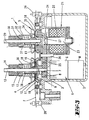
Fig. 2 , vergrößert dargestellt. - Mit der Ziffer 1 ist als Ganzes eine Fadenbremsvorrichtung bezeichnet. Sie besitzt ein kastenförmiges Gehäuse 2, welches durch einen Deckel 3 verschlossen ist. Das im Grundriß langgestreckte, rechteckig ausgebildete Gehäuse 2 weist zwei in Längsrichtung hintereinander angeordnete Tellerbremsen 4, 5 auf.
- Die erste Tellerbremse 4 ist mit einem elektrischen Antrieb 6 ausgestattet, welcher sich aus einem Elektromotor M und einem nachgeschalteten Getriebe G zusammensetzt. Sowohl der Elektromotor M als auch das Getriebe G befinden sich im Inneren des Gehäuses 2 derart, daß das Getriebe G an der Unterseite des Deckels 3 festgeschraubt ist. Die als Verlängerung der Getriebe-Antriebswelle ausgebildete Antriebswelle 7 durchgreift den Deckel 3 und trägt drehfest ein mit ihr verbundenes, stirngezahntes Antriebsrad 8. Weiterhin trägt die Antriebswelle 7, dem Antriebsrad 8 nachgeordnet, einen Drehkranz 9 mit einem auf seiner freien Stirnfläche vorgesehenen Reibbelag 10, gegen welchen die innere Bodenfläche eines ersten Tellers 11 tritt. An der äußeren Bodenfläche dieses ersten Tellers 11 stützt sich die äußere Bodenfläche eines zweiten Tellers 12 ab, welche Teller 11, 12 zwischen sich einen keilförmig ausgebildeten Spalt belassen. In ein Innengewinde des Drehkranzes 9 ist eine Gewindestange 13 eingeschraubt. Diese trägt an ihrem freien Ende eine Einstellmutter 14, welche unter Zwischenlage einer auf der Gewindestange 13 verschieblichen Hülse 15 auf eine Vorspann-Druckfeder 16 einwirkt. Deren anderes Ende beaufschlagt den Boden einer topfförmigen Büchse 17, die ihrerseits einen Druckkragen 18 in Richtung des zweiten Tellers 12 beaufschlagt und damit den zweiten Teller 12 in Richtung des ersten Tellers 11. Die Einstellmutter 14, die topfförmige Büchse 17 und der Druckkragen 18 bilden dabei ein teleskopartiges Gehäuse, in welchem die nach einer Kegelstumpflinie verlaufende Vorspann-Druckfeder 16 staubgeschützt einliegt. Die Anordnung der Druckfeder 16 ist derart, daß sich der durchmessergrößere Gewindegang an dem Boden der topfförmigen Büchse 17 abstützt.
- Den Tellern 11, 12 ist eine Fadenrolle 19 vorgeordnet, deren Achse quer zur Längserstreckung des Gehäuses 2 verläuft und damit quer zur Fadendurchzugsrichtung. Im Anschluß an die Fadenrolle 19 trägt der Deckel 3 eine Fadenöse 20 zum Durchtritt des Fadens F.
- Der Tellerbremse 5 ist gehäuseinnenseitig ein Elektromagnet 21 zugeordnet, welcher ebenfalls von dem Deckel 3 getragen ist. Der Wicklungsträger 22 ist mittig durchsetzt von einer einen Kern bildenden Antriebswelle 23, welche parallel zur Antriebswelle 7 der Tellerbremse 4 verläuft. Es liegt eine drehbare, jedoch axial unverschiebliche Anordnung der Antriebswelle 23 zum Elektromagneten 21 vor. Auf gleicher Höhe zum Antriebsrad 8 trägt die Antriebswelle 23 ein aus Kunststoff bestehendes Zahnrad 24. Dieses und das Antriebsrad 8 kämmen mit einem Zwischenrad 25, welches um eine im Deckel 3 angeordnete Achse 26 drehbar ist. Da beide Räder 8, 24 gleichen Durchmesser besitzen, laufen die Antriebswellen 7, 23 synchron um.
- Jenseits des mit der Antriebswelle 23 fest verbundenen Zahnrades 24 trägt die Antriebswelle 23 drehfest eine Zwischenhülse 27, die ihrerseits zur drehfesten Festlegung eines ersten Bremselementes 28 dient, welches ebenfalls als erster Teller ausgebildet ist und in seiner Form und Anordnung dem ersten Teller 11 der Tellerbremse 4 entspricht. Somit ist auch dieser vom ersten Bremselement 28 ausgebildete erste Teller drehangetrieben. Für das erste Bremselement 28 ist magnetkraftdurchlässiges Material gewählt. Beim Ausführungsbeispiel handelt es sich um Messing. In Verlängerung der Antriebswelle 23 erstreckt sich ebenfalls eine Gewindestange 29. Auch sie trägt eine Einstellmutter 30, die über eine Hülse 31 auf eine Vorspann-Druckfeder 32 einwirkt. Es liegt auch hier wiederum eine gekapselte Ausgestaltung der Vorspann-Druckfeder 32 in einem Gehäuse vor, wozu eine topfförmige Büchse 33 und ein Druckkragen 34 vorgesehen sind. Die Einkapselung der Tellerbremse 5 entspricht derjenigen der Tellerbremse 4, so daß hierauf nicht weiter eingegangen wird. Der Druckkragen 34 beaufschlagt das zweite, zum ersten Bremselement 28 bewegliche Bremselement 35, welches tellerförmig ausgebildet ist und dem zweiten Teller 12 der Tellerbremse 4 entspricht.
- Ihre Zentrierung erhalten die Teller 11, 12 sowie die tellerförmigen Bremselemente 28, 35 durch mit den Antriebswellen 7, 23 drehfest verbundene Zentrierhülsen 36 bzw. 37, welche die Gewindestangen 13 bzw. 29 teilweise umgreifen.
- Im Gegensatz zur Tellerbremse 4 ist die Tellerbremse 5 durch Magnetkraft wirkungsmodulierbar. Dabei wird die Magnetkraft auf das tellerartige zweite Bremselement 35 über die den Kern bildende Antriebswelle 23 übertragen. Sowohl der Kern -Antriebswelle 23- als auch der zweite Teller, zweites Bremselement 35, bestehen aus schnellentmagnetisierendem Material.
- Wie der Tellerbremse 4 ist auch der Tellerbremse 5 eine Fadenrolle 38 und eine Fadenöse 39 zugeordnet.
- Die Tellerbremse 5 wirkt in der Weise, daß im Takt mit der Arbeitsweise der Webmaschine lediglich die Auflagekraft des in Richtung auf das erste Bremselement 28 federvorgespannten zweiten Bremselementes 35 auf den Faden F modulierbar ist. Die entsprechende Modulierung erfolgt dabei durch Strom/Spannungsstöße und wird von der Hauptwelle der Webmaschine gesteuert. Es erfolgt dabei eine Bremsung mit variabler Kraft. Während des Fadendurchlaufes ist der Drehantrieb der Fadenbremsvorrichtung eingeschaltet. Ein Aussetzen des Drehantriebes der Fadenbremsvorrichtung erfolgt bei Ausbleiben der strom/Spannungsstöße selbsttätig. Durch den Drehantrieb ist gewährleistet, daß die Bremselemente eine gleichmäßige Abnutzung erhalten und sich keine Spuren wie beim Stand der Technik eingraben. Ferner wird einer Verschmutzung weitgehend entgegengewirkt.
- Jede Tellerbremse 4, 5 ist mit einem unterhalb des ersten Tellers 11, 28 befindlichen Dichtkragen 40 bzw. 41 ausgestattet, um auch den Innenraum des Gehäuses 2 vor Verstaubung bzw. Verschmutzung zu schützen.
Claims (14)
- Bremse für laufende Fäden (F), mit einem ersten Bremselement (28) und einem zweiten dazu bewegbaren Bremselement (35), welches magnetkraftbetätigt den zwischen den Bremselementen (28, 35) durchgezogenen Faden (F) kraftmodulierbar beaufschlagt, wobei die Auflagekraft des zweiten Bremselementes (35) auf dem Faden (F) modulierbar ist, dadurch gekennzeichnet, dass die Auflagekraft des zweiten Bremselementes (35) in Richtung auf das erste Bremselement (28) federvorgespannt ist.
- Bremse nach Anspruch 1, dadurch gekennzeichnet, dass die ersten und zweiten Bremselemente (28, 35) Teller einer Tellerbremse (5) sind.
- Bremse nach Anspruch 2, dadurch gekennzeichnet, dass der das erste Bremselement (28) bildende erste Teller drehangetrieben ist.
- Bremse nach Anspruch 1, dadurch gekennzeichnet, dass das erste Bremselement (28) aus einem magnetkraftdurchlässigen Material besteht und vor einem Elektromagneten (21) angeordnet ist.
- Bremse nach Anspruch 4, dadurch gekennzeichnet, dass die Magnetkraft über einen von der Antriebswelle (23) des das erste Bremselement (28) bildenden Tellers ausgebildeten Kern übertragen wird.
- Bremse nach wenigstens einem der vorhergehenden Ansprüche, dadurch gekennzeichnet, dass eine sich in Verlängerung einer Antriebswelle (23) erstreckende Gewindestange (29) eine Einstellmutter (30) für eine Vorspann-Druckfeder (32) trägt.
- Bremse nach Anspruch 6, dadurch gekennzeichnet, dass die Vorspann-Druckfeder (32) in einem teleskopartigen Gehäuse gekapselt ist.
- Bremse nach wenigstens einem der vorhergehenden Ansprüche, gekennzeichnet durch zwei nebeneinander angeordnete, drehangetriebene Tellerbremsen (4, 5), von denen wenigstens die eine (5) bewegungsfrei durch Magnetkraft wirkungsmodulierbar ist.
- Bremse nach wenigstens einem der vorhergehenden Ansprüche, dadurch gekennzeichnet, dass eine von zwei Tellerbremsen-Antriebswellen (7, 23) die Verlängerung der Abtriebswelle eines elektrischen Antriebes (6) ist und die Antriebswelle (23) der anderen Tellerbremse (5) über ein Zwischenrad (25) synchron zur einen Tellerbremse (4) angetrieben ist.
- Bremse nach wenigstens einem der vorhergehenden Ansprüche, dadurch gekennzeichnet, dass die Modulierung der Magnetkraft von der Webmaschine steuerbar ist.
- Bremse nach Anspruch 10, dadurch gekennzeichnet, dass die Modulierung von der Hauptwelle der Webmaschine gesteuert durch Strom-/Spannungsstöße erfolgt.
- Bremse nach wenigstens einem der vorhergehenden Ansprüche, dadurch gekennzeichnet, dass die Bremsung mit variabler Kraft erfolgt.
- Bremse nach wenigstens einem der vorhergehenden Ansprüche, dadurch gekennzeichnet, dass der Drehantrieb der Bremse bei Ausbleiben der Strom/Spannungsstöße selbsttätig aussetzt.
- Bremse nach wenigstens einem der vorhergehenden Ansprüche, dadurch gekennzeichnet, dass die Antriebswelle (23) bzw. der das zweite Bremselement (35) bildende Teller aus schnellentmagnetisierendem Material besteht.
Applications Claiming Priority (3)
| Application Number | Priority Date | Filing Date | Title |
|---|---|---|---|
| DE29721138U DE29721138U1 (de) | 1997-12-03 | 1997-12-03 | Fadenbremsvorrichtung |
| DE2972138 | 1997-12-03 | ||
| PCT/EP1998/007881 WO1999028228A1 (de) | 1997-12-03 | 1998-12-03 | Fadenbremsvorrichtung |
Publications (2)
| Publication Number | Publication Date |
|---|---|
| EP1218275A1 EP1218275A1 (de) | 2002-07-03 |
| EP1218275B1 true EP1218275B1 (de) | 2008-02-27 |
Family
ID=8049276
Family Applications (1)
| Application Number | Title | Priority Date | Filing Date |
|---|---|---|---|
| EP98967145A Expired - Lifetime EP1218275B1 (de) | 1997-12-03 | 1998-12-03 | Fadenbremsvorrichtung |
Country Status (3)
| Country | Link |
|---|---|
| EP (1) | EP1218275B1 (de) |
| DE (2) | DE29721138U1 (de) |
| WO (1) | WO1999028228A1 (de) |
Families Citing this family (3)
| Publication number | Priority date | Publication date | Assignee | Title |
|---|---|---|---|---|
| ES2594884T3 (es) | 2000-04-25 | 2016-12-23 | Align Technology, Inc. | Sistemas para reposicionar dientes con aparatos que presentan rigidez variable |
| ES2543131T3 (es) * | 2004-12-22 | 2015-08-14 | Novozymes North America, Inc. | Enzimas para tratamiento de almidón |
| JP2020204106A (ja) * | 2019-06-18 | 2020-12-24 | 株式会社島精機製作所 | 糸張力調整装置 |
Family Cites Families (5)
| Publication number | Priority date | Publication date | Assignee | Title |
|---|---|---|---|---|
| DE2758335C2 (de) * | 1977-12-27 | 1986-04-17 | W. Schlafhorst & Co, 4050 Mönchengladbach | Fadenbremse |
| DE4130301A1 (de) * | 1991-09-12 | 1993-03-18 | Schlafhorst & Co W | Rotierend angetriebene bremstelleranordnung eines fadenspanners |
| US5238202A (en) * | 1992-04-15 | 1993-08-24 | Intronics, Inc. | Yarn tensioning apparatus |
| EP0756028B1 (de) * | 1995-07-24 | 2000-01-19 | Sulzer RàTi Ag | Elektromagnetische Fadenbremse und Webmaschine mit einer Fadenbremse |
| DE29517027U1 (de) * | 1995-10-27 | 1997-04-10 | BARTH-TEX Instruments + Software GmbH + Co, 72411 Bodelshausen | Fadenbremse |
-
1997
- 1997-12-03 DE DE29721138U patent/DE29721138U1/de not_active Expired - Lifetime
-
1998
- 1998-12-03 WO PCT/EP1998/007881 patent/WO1999028228A1/de not_active Ceased
- 1998-12-03 DE DE59814180T patent/DE59814180D1/de not_active Expired - Fee Related
- 1998-12-03 EP EP98967145A patent/EP1218275B1/de not_active Expired - Lifetime
Also Published As
| Publication number | Publication date |
|---|---|
| DE59814180D1 (de) | 2008-04-10 |
| DE29721138U1 (de) | 1999-04-08 |
| EP1218275A1 (de) | 2002-07-03 |
| WO1999028228A1 (de) | 1999-06-10 |
Similar Documents
| Publication | Publication Date | Title |
|---|---|---|
| EP0499218B1 (de) | Fadenbremse | |
| CH691904A5 (de) | Vorrichtung zur Einstellung der Spannung eines Fadens. | |
| CH665412A5 (de) | Spannvorrichtung fuer fadenfoermiges gut. | |
| EP0093189B1 (de) | Zuführeinrichtung für Schussfäden, Fangfäden od. dgl. bei Textilmaschinen | |
| DE19531579C1 (de) | Fadenbremse | |
| DE19720795A1 (de) | Fadenbremse und damit ausgerüstete Textilmaschine und Fadenliefervorrichtung | |
| EP0524429B1 (de) | Vorrichtung zur unterschiedlichen Bremsung laufender Fäden, Drähte oder dergleichen | |
| DE69213135T2 (de) | Fadenbremse | |
| DE4130301A1 (de) | Rotierend angetriebene bremstelleranordnung eines fadenspanners | |
| DE2419446C2 (de) | Elektromagnetisch betätigbare Kupplung für Textilmaschinen | |
| WO1995011183A1 (de) | Verfahren und vorrichtung zum führen eines bandes | |
| EP0215416A1 (de) | Automatischer Mähkopf für ein Buschmägerät | |
| DE3403733C2 (de) | ||
| DE2711752A1 (de) | Kupplungsvorrichtung, insbesondere zur steuerung des garnspulenantriebs bei textilmaschinen | |
| EP1218275A1 (de) | Fadenbremsvorrichtung | |
| DE2848587A1 (de) | Ausloesevorrichtung fuer die selbsttaetige schnellbremsung bewegter maschinenteile, insbesondere von webmaschinen | |
| DE3437455A1 (de) | Vorrichtung zum verhindern eines wicklers im falle eines bahnrisses | |
| DE3910888C2 (de) | ||
| DE2941361C2 (de) | Seiltrieb | |
| CH681718A5 (de) | ||
| DE3820288C1 (en) | Thread-transport apparatus for textile machines | |
| EP0699613B1 (de) | Spulengatter für Spulen mit fadenförmigem Gut | |
| EP0280025B1 (de) | Fadenbremsvorrichtung | |
| DE4122304A1 (de) | Kupplung/bremse-einheit | |
| CH617250A5 (de) |
Legal Events
| Date | Code | Title | Description |
|---|---|---|---|
| PUAI | Public reference made under article 153(3) epc to a published international application that has entered the european phase |
Free format text: ORIGINAL CODE: 0009012 |
|
| 17P | Request for examination filed |
Effective date: 20000519 |
|
| AK | Designated contracting states |
Kind code of ref document: A1 Designated state(s): AT BE CH CY DE DK ES FI FR GB GR IE IT LI LU MC NL PT SE |
|
| RTI1 | Title (correction) |
Free format text: YARN BRAKING DEVICE |
|
| RBV | Designated contracting states (corrected) |
Designated state(s): AT BE CH CY DE DK ES FI FR GB GR IE IT LI LU MC NL PT SE |
|
| R17P | Request for examination filed (corrected) |
Effective date: 20000519 |
|
| RBV | Designated contracting states (corrected) |
Designated state(s): DE IT LI |
|
| R17P | Request for examination filed (corrected) |
Effective date: 20000519 |
|
| RIN1 | Information on inventor provided before grant (corrected) |
Inventor name: VALSECCHI, EUGENIO |
|
| RBV | Designated contracting states (corrected) |
Designated state(s): BE DE LI |
|
| R17P | Request for examination filed (corrected) |
Effective date: 20000519 |
|
| RBV | Designated contracting states (corrected) |
Designated state(s): BE DE |
|
| GRAP | Despatch of communication of intention to grant a patent |
Free format text: ORIGINAL CODE: EPIDOSNIGR1 |
|
| RBV | Designated contracting states (corrected) |
Designated state(s): DE IT |
|
| GRAS | Grant fee paid |
Free format text: ORIGINAL CODE: EPIDOSNIGR3 |
|
| GRAA | (expected) grant |
Free format text: ORIGINAL CODE: 0009210 |
|
| AK | Designated contracting states |
Kind code of ref document: B1 Designated state(s): DE IT |
|
| REF | Corresponds to: |
Ref document number: 59814180 Country of ref document: DE Date of ref document: 20080410 Kind code of ref document: P |
|
| PLBE | No opposition filed within time limit |
Free format text: ORIGINAL CODE: 0009261 |
|
| STAA | Information on the status of an ep patent application or granted ep patent |
Free format text: STATUS: NO OPPOSITION FILED WITHIN TIME LIMIT |
|
| 26N | No opposition filed |
Effective date: 20081128 |
|
| PG25 | Lapsed in a contracting state [announced via postgrant information from national office to epo] |
Ref country code: DE Free format text: LAPSE BECAUSE OF NON-PAYMENT OF DUE FEES Effective date: 20090701 |
|
| PGFP | Annual fee paid to national office [announced via postgrant information from national office to epo] |
Ref country code: IT Payment date: 20141218 Year of fee payment: 17 |
|
| PG25 | Lapsed in a contracting state [announced via postgrant information from national office to epo] |
Ref country code: IT Free format text: LAPSE BECAUSE OF NON-PAYMENT OF DUE FEES Effective date: 20151203 |