EP1217398A2 - Verfahren zur Positionierung einer Vielzahl von Glasfaserenden in einer Matrixstruktur - Google Patents
Verfahren zur Positionierung einer Vielzahl von Glasfaserenden in einer Matrixstruktur Download PDFInfo
- Publication number
- EP1217398A2 EP1217398A2 EP01125931A EP01125931A EP1217398A2 EP 1217398 A2 EP1217398 A2 EP 1217398A2 EP 01125931 A EP01125931 A EP 01125931A EP 01125931 A EP01125931 A EP 01125931A EP 1217398 A2 EP1217398 A2 EP 1217398A2
- Authority
- EP
- European Patent Office
- Prior art keywords
- glass
- quartz
- fiber ends
- fiber
- plastic
- Prior art date
- Legal status (The legal status is an assumption and is not a legal conclusion. Google has not performed a legal analysis and makes no representation as to the accuracy of the status listed.)
- Withdrawn
Links
Images

Classifications
-
- G—PHYSICS
- G02—OPTICS
- G02B—OPTICAL ELEMENTS, SYSTEMS OR APPARATUS
- G02B6/00—Light guides; Structural details of arrangements comprising light guides and other optical elements, e.g. couplings
- G02B6/24—Coupling light guides
- G02B6/36—Mechanical coupling means
- G02B6/3628—Mechanical coupling means for mounting fibres to supporting carriers
- G02B6/3664—2D cross sectional arrangements of the fibres
- G02B6/3672—2D cross sectional arrangements of the fibres with fibres arranged in a regular matrix array
-
- G—PHYSICS
- G02—OPTICS
- G02B—OPTICAL ELEMENTS, SYSTEMS OR APPARATUS
- G02B6/00—Light guides; Structural details of arrangements comprising light guides and other optical elements, e.g. couplings
- G02B6/04—Light guides; Structural details of arrangements comprising light guides and other optical elements, e.g. couplings formed by bundles of fibres
- G02B6/06—Light guides; Structural details of arrangements comprising light guides and other optical elements, e.g. couplings formed by bundles of fibres the relative position of the fibres being the same at both ends, e.g. for transporting images
-
- G—PHYSICS
- G02—OPTICS
- G02B—OPTICAL ELEMENTS, SYSTEMS OR APPARATUS
- G02B6/00—Light guides; Structural details of arrangements comprising light guides and other optical elements, e.g. couplings
- G02B6/24—Coupling light guides
- G02B6/36—Mechanical coupling means
- G02B6/3628—Mechanical coupling means for mounting fibres to supporting carriers
- G02B6/3632—Mechanical coupling means for mounting fibres to supporting carriers characterised by the cross-sectional shape of the mechanical coupling means
- G02B6/3644—Mechanical coupling means for mounting fibres to supporting carriers characterised by the cross-sectional shape of the mechanical coupling means the coupling means being through-holes or wall apertures
-
- G—PHYSICS
- G02—OPTICS
- G02B—OPTICAL ELEMENTS, SYSTEMS OR APPARATUS
- G02B6/00—Light guides; Structural details of arrangements comprising light guides and other optical elements, e.g. couplings
- G02B6/24—Coupling light guides
- G02B6/36—Mechanical coupling means
- G02B6/38—Mechanical coupling means having fibre to fibre mating means
- G02B6/3807—Dismountable connectors, i.e. comprising plugs
- G02B6/3833—Details of mounting fibres in ferrules; Assembly methods; Manufacture
- G02B6/3834—Means for centering or aligning the light guide within the ferrule
-
- G—PHYSICS
- G02—OPTICS
- G02B—OPTICAL ELEMENTS, SYSTEMS OR APPARATUS
- G02B6/00—Light guides; Structural details of arrangements comprising light guides and other optical elements, e.g. couplings
- G02B6/24—Coupling light guides
- G02B6/36—Mechanical coupling means
- G02B6/38—Mechanical coupling means having fibre to fibre mating means
- G02B6/3807—Dismountable connectors, i.e. comprising plugs
- G02B6/3873—Connectors using guide surfaces for aligning ferrule ends, e.g. tubes, sleeves, V-grooves, rods, pins, balls
- G02B6/3885—Multicore or multichannel optical connectors, i.e. one single ferrule containing more than one fibre, e.g. ribbon type
Definitions
- the invention relates to a method for moving a plurality of Fiber ends of a bundle of optical fibers, in particular glass, Quartz or plastic fibers in a variety of predetermined positions and a method for producing one with a plug device connectable glass, quartz or plastic fiber end.
- glass fibers side by side arranged in a one-dimensional array and with the connector of a fiber optic cable.
- such a method did not allow one two-dimensional glass fiber array with, for example, 2 x 2 to 40 x 40 Spend fiber in a connector so that there is a fiber cable with a variety of glass fibers in a two-dimensional, for example square or rectangular matrix.
- the State of the art method no exact positioning in the Range of a few micrometers ( ⁇ m) from very many glass fiber ends Small distance.
- the object of the invention is therefore to provide a method with which this Disadvantages can be overcome, especially a method indicate a very precise positioning in a two-dimensional Matrix with spacing of the fiber ends of a few ⁇ m possible. In particular, this should simplify the point-to-point assignment of two Glass fiber ends are made possible. Furthermore, the process is said to be a allow extensive automation of the manufacture of fiber optic cables.
- this is achieved in that the fiber ends on a Fixing device comprising a plurality of openings for the Fiber ends, are applied and the fixing device or the Fiber ends or fixing device and fiber ends are moved in such a way that the fiber ends due to the movement through the opening of the Pass through the fixation device and into the through the openings predefined position, for example within a two-dimensional one Matrix.
- glass fiber ends can be set to ⁇ Spend 2 ⁇ m exactly in one position, with the single glass fiber with Core, cladding and protective coating with a diameter of 20 ⁇ m, have in particular 100 microns to 1000 microns, in particular 260 microns can.
- the stripped glass fiber ends without protective coating consisting of core and cladding can have a diameter in the range Have 50 to 800 microns.
- One possible configuration of the fixing device consists in the training as a perforated plate, the individual openings being formed by webs and the webs are at a fixed distance.
- a fixing device in which the Opening sizes varied by flexible webs in a given range can be.
- Such a fixing device allows the individual fiber ends first inserted into a relatively wide opening can be.
- the width of these openings may be a maximum be chosen so that they just penetrate a second fiber prevented. The exact positioning of the individual fibers is followed by Carrying out the individual fibers reduced their size.
- Another advantage is that the glass fibers can be used by several such fixing devices can be performed, the width of the Openings of the individual fixing devices can be individually adjusted.
- the advantage is in particular that by inserting as many plates as possible the selection of insertion processes is reduced. to Separation of individual cables consisting of two hotplates each can Plates are then pulled apart.
- the invention also relates to a method for producing a Connector connectable fiber optic end that a variety of includes individual glass fibers.
- a method according to the invention for the production of a Plug device connectable fiber end includes the step of Positioning the individual glass fibers with the help of the invention Procedure, a preliminary fixation of the fiber ends, their positioning and final fixation.
- the final fixation of the fiber ends can for example by pouring with a casting compound and then Curing can be achieved. This final fixation can, for example can be integrated into a plug.
- the glass fibers are now in a two-dimensional matrix are arranged, ground and polished so that one in one Layered fiber array results.
- the in one Glass fiber array arranged individual glass fiber ends without Protective coating, i.e. the glass fiber ends just settle together from the fiberglass core and the cladding.
- Plastic and / or an adhesive are preferably used as the casting compound.
- the invention is intended to be based on the exemplary embodiments to be discribed.
- the following exemplary embodiments are can refer to glass fibers as optical fibers Method according to the invention also in any other type of Use optical fibers, for example quartz or plastic fibers, without departing from the invention.
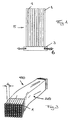
- Figure 1 shows the operation of the inventive method for Positioning a variety of fiber optic elements using a exemplary device.
- Each individual fiber of the fiber optic cable consists of a fiberglass core, a so-called cladding or cladding glass and a protective layer that surrounds the cladding or cladding glass.
- the protective layer was in the range Fiber ends 1 removed from the individual glass fibers.
- the single ones Glass fiber ends are applied to a fixing device 3 which is designed as a perforated plate with webs, the webs one have predetermined web spacing so that an opening with constant Opening diameter is formed.
- the opening size is just such that a maximum of one fiber end can pass through such an opening.
- the bundle 5 of fiber ends 1 is placed on the perforated plate 3. Now the bundle of glass fiber ends 1 and / or the perforated plate 3 as with indicated by arrow 6 moves, for example vibrated, so if the individual glass fiber ends pass through the openings, positioned and from the openings of the plate after it has passed through the same provisionally fixed.
- 100% of the stripped fibers fall, that is the fibers without Protective coating in the end area, through the holes and these fill these out.
- the existing glass fiber ends are finally fixed by means of a casting compound.
- the fiber ends are preferably filled with a plastic / adhesive and then cured. This will result in a final fixation of the Fiber ends reached in the desired position.
- the cable end produced in this way can then be ground to size and polished so that you have an in-plane fiber array receives.
- the flexible matrix consists of a system of crossing webs 10, 12 defining a plurality of openings 14 in a matrix structure.
- the distance between the webs is dimensioned so that straight through the openings 14 the penetration of a second fiber is prevented. It should be noted here that this is only possible if the protective coating of the fiber is covered on the total diameter of the fiber is less than 50%.
- the individual glass fiber ends are then packed tightly into a matrix and have a distance equal to the web width of the individual webs 10, 12 equivalent.
- the Use of a flexible matrix after the preliminary positioning of the Fixing device cast this with a mass and then the one Connector connected cable ends ground to size and polished.
- the Fiber optic cable 100 comprises a plurality of fiber optic ends 1, which in one Array are arranged.
- the size of the array can be, for example, 10 x 10 or 35 x 35 fibers or a non-square fiber array with, for example, 16 x 32 glass fibers.
- the distance d of the individual fiber cores to each other in the present Embodiment 125 microns, the tolerance in the spatial deviation ⁇ 2 microns.
- the individual glass fibers are composed of a glass fiber core with a diameter in the range of 50 microns, a cladding that the Glass fiber core surrounds, as well as a protective jacket.
- the fiber optic cable with Protective coating has a diameter of approximately 110 to 120 ⁇ m on. Arrays of other geometries or with are of course also Glass fibers of other dimensions conceivable without the thought of Invention is deviated.
- the plurality of glass fibers surround a sheath 110.
- Quartz glass, other glasses or a can be used as the glass fiber material Plastic material can be used.
- the glass fiber surface comprises e.g. an acrylate coating. Both multi-mode and single-mode fibers can be used be used.
- a complete fiber optic cable results when the array of Glass fibers, a connector is placed on each end.
Landscapes
- Physics & Mathematics (AREA)
- General Physics & Mathematics (AREA)
- Optics & Photonics (AREA)
- Optical Fibers, Optical Fiber Cores, And Optical Fiber Bundles (AREA)
- Mechanical Coupling Of Light Guides (AREA)
- Optical Couplings Of Light Guides (AREA)
Abstract
- die Glas-, Quarz-, oder Kunststoffaserenden werden auf eine Fixiereinrichtung umfassend eine Vielzahl von Öffnungen für die Glas-, Quarz- oder Kunststoffaserenden aufgebracht
- die Fixiereinrichtung und/oder die Vielzahl von Glas-, Quarz- oder Kunststoffaserenden werden derart bewegt, daß die Glas-, Quarz oder Kunststoffaserenden durch die Öffnungen der Fixiereinrichtung hindurchtreten, so daß die Glas-, Quarz oder Kunststoffaserenden in die vorgegebene Position gelangen.
Description
- Figur 1
- den Aufbau zur Durchführung des erfindungsgemäßen Verfahrens, Glasfasern mittels Bewegung zu positionieren.
- Figur 2a und 2b
- eine Lochplatte mit flexiblen Lochöffnungen und Distanzhaltern, die im zusammengeschobenen Zustand einen definierten Abstand garantieren.
- Figur 3
- ein mittels des erfindungsgemäßen Verfahrens hergestelltes Glasfaserkabel mit einer Vielzahl von Glasfasern, angeordnet in einer zweidimensionalen Matrix.
Claims (11)
- Verfahren zum Verbringen einer Vielzahl von Faserenden (1) eines Bündels (5) von Lichtwellenleitern, insbesondere Glas-, Quarz- oder Kunststoffasern in eine Vielzahl von vorgegebenen Positionen, umfassend folgende Schritte:1.1 die Glas-, Quarz- oder Kunststoffaserenden (1) werden auf eine Fixiereinrichtung (3) umfassend eine Vielzahl von Öffnungen für die Glas-, Quarz- oder Kunststoffaserenden aufgebracht1.2 die Fixiereinrichtung (3) und/oder die Vielzahl von Glas-, Quarz- oder Kunststoffaserenden (1) werden derart bewegt, daß die Glas-, Quarz-oder Kunststoffaserenden (1) durch die Öffnungen der Fixiereinrichtung (3) hindurchtreten, so daß die Glas-, Quarz- oder Kunststoffaserenden in die vorgegebene Position gelangen.
- Verfahren nach Anspruch 1, dadurch gekennzeichnet, daß
die Glas-, Quarz- oder Kunststoffaserenden (1) und/oder Fixiereinrichtungen (3) periodisch bewegt, insbesondere in Schwingung versetzt werden. - Verfahren nach einem der Ansprüche 1 bis 2, dadurch gekennzeichnet, daß
die Fixiereinrichtung (3) wenigstens einer starren Matrix mit Öffnungen (14), insbesondere eine Lochplatte umfaßt. - Verfahren nach Anspruch 3, dadurch gekennzeichnet, daß
der Abstand der Stege der Matrix fest ist und derart gewählt, daß nur genau ein Faserende (1) die Öffnung (14) durchdringen kann. - Verfahren nach Anspruch 4, dadurch gekennzeichnet, daß
der Abstand der Stege (10,12) < 100 µm ist. - Verfahren nach einem der Ansprüche 1 bis 2, dadurch gekennzeichnet, daß
die Fixiereinrichtung wenigstens eine flexible Matrix mit Öffnungen umfaßt, wobei die Größe der Öffnungen in einem vorgegebenen Bereich variiert werden kann. - Verfahren zur Herstellung eines mit einer Steckereinrichtung verbindbaren Glas-, Quarz oder Kunststoffaserendes eines Glas-, Quarz-, oder Kunststoffaserkabels, umfassend eine Vielzahl von einzelnen Fasern mit folgenden Schritten:7.1 die Faserenden werden an eine vorgegebene Position verbracht, wobei die Positionierung der überwiegenden Zahl von Faserenden der Vielzahl von einzelnen Fasern des Glas-, Quarz- oder Kunststoffaserkabels mittels eines Verfahrens gemäß einem der Ansprüche 1 bis 8 vorgenommen wird7.2 die Faserenden werden nach der Positionierung vorläufig fixiert7.3 die Faserenden werden in der vorgegebenen Position endgültig fixiert.
- Verfahren nach Anspruch 7, dadurch gekennzeichnet, daß
das endgültige Fixieren durch Ausgießen und anschließendes Aushärten erfolgt, wobei das Ausgießen mit einem Kunststoff und/oder Kleber als Gießmasse erfolgt. - Verfahren nach einem der Ansprüche 1 bis 8, dadurch gekennzeichnet, daß
die Faserenden Fasern ohne Schutzbeschichtung sind. - Verfahren nach Anspruch 9, dadurch gekennzeichnet, daß
die Schutzbeschichtung der Faser bezogen auf den Gesamtdurchmesser der Faser weniger als 50 % beträgt. - Verfahren nach einem der Ansprüche 7 bis 10, dadurch gekennzeichnet, daß
das Glas-, Quarz- oder Kunststoffaserende geschliffen und poliert wird, ergebend ein Glas-, Quarz- oder Kunststoffaser-Array.
Applications Claiming Priority (2)
| Application Number | Priority Date | Filing Date | Title |
|---|---|---|---|
| DE10057127 | 2000-11-16 | ||
| DE10057127A DE10057127A1 (de) | 2000-11-16 | 2000-11-16 | Verfahren zum Verbringen einer Vielzahl von Faserenden in eine vorgegebene Position |
Publications (2)
| Publication Number | Publication Date |
|---|---|
| EP1217398A2 true EP1217398A2 (de) | 2002-06-26 |
| EP1217398A3 EP1217398A3 (de) | 2004-05-12 |
Family
ID=7663701
Family Applications (1)
| Application Number | Title | Priority Date | Filing Date |
|---|---|---|---|
| EP01125931A Withdrawn EP1217398A3 (de) | 2000-11-16 | 2001-10-31 | Verfahren zur Positionierung einer Vielzahl von Glasfaserenden in einer Matrixstruktur |
Country Status (5)
| Country | Link |
|---|---|
| US (1) | US6542676B2 (de) |
| EP (1) | EP1217398A3 (de) |
| JP (1) | JP2002267853A (de) |
| CA (1) | CA2363260A1 (de) |
| DE (1) | DE10057127A1 (de) |
Cited By (1)
| Publication number | Priority date | Publication date | Assignee | Title |
|---|---|---|---|---|
| WO2010042042A1 (en) * | 2008-10-09 | 2010-04-15 | Parans Solar Lighting Ab | Fitting device and method of fitting a fibre cabling |
Families Citing this family (6)
| Publication number | Priority date | Publication date | Assignee | Title |
|---|---|---|---|---|
| US6944379B2 (en) * | 2000-11-16 | 2005-09-13 | Schott Ag | Method for transferring a large number of fiber ends into a specified position |
| JP4252741B2 (ja) * | 2001-06-07 | 2009-04-08 | 富士フイルム株式会社 | 光源装置 |
| US6816654B1 (en) * | 2003-06-27 | 2004-11-09 | Dimitry Grabbe | Fiber array ferrule and method of making |
| JP6038882B2 (ja) * | 2011-04-20 | 2016-12-07 | マッパー・リソグラフィー・アイピー・ビー.ブイ. | 光ファイバの構成体及びこのような構成体を形成する方法 |
| US8979390B2 (en) | 2011-11-28 | 2015-03-17 | International Business Machines Corporation | Ferrule of multilayer waveguide connector |
| US20250044522A1 (en) * | 2023-07-31 | 2025-02-06 | Lumentum Operations Llc | Apparatus for aligning multiple fibers |
Family Cites Families (12)
| Publication number | Priority date | Publication date | Assignee | Title |
|---|---|---|---|---|
| JPS59121983A (ja) * | 1982-12-28 | 1984-07-14 | Fujitsu Ltd | 光半導体素子アレイと光フアイバとの光学的結合方法 |
| JPH04288507A (ja) * | 1991-03-18 | 1992-10-13 | Nippon Telegr & Teleph Corp <Ntt> | 光ファイバ二次元アレイモジュール |
| US5346583A (en) * | 1993-09-02 | 1994-09-13 | At&T Bell Laboratories | Optical fiber alignment techniques |
| US5394498A (en) * | 1993-11-05 | 1995-02-28 | At&T Corp. | Optical fiber array and process of manufacture |
| US5907650A (en) * | 1997-06-26 | 1999-05-25 | Fiberguide Industries, Inc. | High precision optical fiber array connector and method |
| US5915055A (en) * | 1997-06-30 | 1999-06-22 | Siecor Corporation | Method and apparatus for connectorizing fiber optic cable |
| WO2000071992A1 (en) * | 1999-05-20 | 2000-11-30 | Illumina, Inc. | Method and apparatus for retaining and presenting at least one microsphere array to solutions and/or to optical imaging systems |
| US6408120B1 (en) * | 1999-10-20 | 2002-06-18 | Agere Systems Guardian Corp. | Fiber array alignment arrangement |
| US6595698B2 (en) * | 2000-06-13 | 2003-07-22 | Siwave, Inc. | High density fiber terminator/connector |
| US6470123B1 (en) | 2000-07-18 | 2002-10-22 | Fiberguide Industries, Inc. | Large optical fiber array assembly and method |
| US6393187B1 (en) * | 2000-08-03 | 2002-05-21 | Lucent Technologies | Optical fiber arrays with reduced return loss and methods for making same |
| US6737223B2 (en) * | 2000-08-07 | 2004-05-18 | Shipley Company, L.L.C. | Fiber optic chip with lenslet array and method of fabrication |
-
2000
- 2000-11-16 DE DE10057127A patent/DE10057127A1/de not_active Withdrawn
-
2001
- 2001-10-31 EP EP01125931A patent/EP1217398A3/de not_active Withdrawn
- 2001-11-14 US US09/990,931 patent/US6542676B2/en not_active Expired - Fee Related
- 2001-11-15 CA CA002363260A patent/CA2363260A1/en not_active Abandoned
- 2001-11-16 JP JP2001352460A patent/JP2002267853A/ja active Pending
Cited By (1)
| Publication number | Priority date | Publication date | Assignee | Title |
|---|---|---|---|---|
| WO2010042042A1 (en) * | 2008-10-09 | 2010-04-15 | Parans Solar Lighting Ab | Fitting device and method of fitting a fibre cabling |
Also Published As
| Publication number | Publication date |
|---|---|
| JP2002267853A (ja) | 2002-09-18 |
| US20020102080A1 (en) | 2002-08-01 |
| DE10057127A1 (de) | 2002-06-06 |
| US6542676B2 (en) | 2003-04-01 |
| CA2363260A1 (en) | 2002-05-16 |
| EP1217398A3 (de) | 2004-05-12 |
Similar Documents
| Publication | Publication Date | Title |
|---|---|---|
| DE2505995C3 (de) | Verfahren zur Herstellung eines Bildzerlegers | |
| DE69510847T2 (de) | Prozess zur Herstellung eines Bauteils zum Anschluss an eine Mehrkernfaser | |
| DE69415567T2 (de) | Herstellungsverfahren für optische Stecker | |
| DE102012220823B4 (de) | Ferrule eines steckverbinders für mehrschichtige wellenleiter, steckverbinder und verfahren | |
| DE2650486A1 (de) | Uebertragungsmischer fuer lichtleitfasern und verfahren zu seiner herstellung | |
| DE69131379T2 (de) | Herstellungs- und Messmethode von integriert-optischen Komponenten | |
| WO2010072286A1 (de) | Micro-distribution-kabel für die optische nachrichtentechnik und verfahren zur herstellung eines micro-distribution-kabels | |
| DE3876068T2 (de) | Spule fuer optische fasern und verfahren zum spannungsfreien bewickeln der spule mit optischen fasern. | |
| DE10057127A1 (de) | Verfahren zum Verbringen einer Vielzahl von Faserenden in eine vorgegebene Position | |
| DE2653354C3 (de) | Verfahren und Vorrichtung zum Bilden von Spleißstellen von Lichtleitkabeln | |
| EP0135224A2 (de) | Verfahren zur Herstellung von Kabeln sowie nach diesem Verfahren hergestellte Kabel, insbesondere optische Kabel | |
| DE2513723A1 (de) | Optisches kabel | |
| DE4406154C2 (de) | Aufnahme mit Knickschutz für einen Faserspleiß | |
| DE10057129A1 (de) | Verfahren zum Verbringen einer Vielzahl von Faserenden in eine vorgegebene Position | |
| DE3516899C2 (de) | Verfahren zum Herstellen einer Lichtleitfaserverbindung | |
| DE10057132A1 (de) | Verfahren zum Verbringen einer Vielzahl von Faserenden in eine vorgegebene Position und vorübergehende Fixierung | |
| DE4341481A1 (de) | Verzweigungseinrichtung und Verfahren zum Herstellen einer Verzweigung eines mehradrigen Lichtwellenleiterkabels | |
| DE60314386T2 (de) | Flexibles faseroptisches kabel mit zentrierten presssitzhülsen | |
| DE19925015C2 (de) | Zweidimensionales Faserarray und Verfahren zu seiner Herstellung | |
| DE10057130A1 (de) | Verfahren zum Verbringen einer Vielzahl von Faserenden in eine vorgegebene Position | |
| DE3921489A1 (de) | Verfahren zur herstellung eines lichtleiters | |
| DE3338493A1 (de) | Verfahren zum spleissen von glasfaser-buendeladern und vorrichtung zur durchfuehrung des verfahrens | |
| DE2514996C2 (de) | Optisches Kabel für Nachrichtenübertragungszwecke | |
| US6944379B2 (en) | Method for transferring a large number of fiber ends into a specified position | |
| DE4240460C2 (de) | Vorrichtung zur lösbaren Verbindung von Lichtwellenleitern |
Legal Events
| Date | Code | Title | Description |
|---|---|---|---|
| PUAI | Public reference made under article 153(3) epc to a published international application that has entered the european phase |
Free format text: ORIGINAL CODE: 0009012 |
|
| 17P | Request for examination filed |
Effective date: 20011031 |
|
| AK | Designated contracting states |
Kind code of ref document: A2 Designated state(s): AT BE CH CY DE DK ES FI FR GB GR IE IT LI LU MC NL PT SE TR |
|
| AX | Request for extension of the european patent |
Free format text: AL;LT;LV;MK;RO;SI |
|
| PUAL | Search report despatched |
Free format text: ORIGINAL CODE: 0009013 |
|
| RIC1 | Information provided on ipc code assigned before grant |
Ipc: 7G 02B 6/04 B Ipc: 7G 02B 6/36 A |
|
| AK | Designated contracting states |
Kind code of ref document: A3 Designated state(s): AT BE CH CY DE DK ES FI FR GB GR IE IT LI LU MC NL PT SE TR |
|
| AX | Request for extension of the european patent |
Extension state: AL LT LV MK RO SI |
|
| RAP1 | Party data changed (applicant data changed or rights of an application transferred) |
Owner name: SCHOTT AG |
|
| AKX | Designation fees paid |
Designated state(s): AT BE CH CY DE DK ES FI FR GB GR IE IT LI LU MC NL PT SE TR |
|
| STAA | Information on the status of an ep patent application or granted ep patent |
Free format text: STATUS: THE APPLICATION IS DEEMED TO BE WITHDRAWN |
|
| 18D | Application deemed to be withdrawn |
Effective date: 20041113 |