EP1217200A2 - Luftansaugkanalsystem für eine Brennkraftmaschine - Google Patents
Luftansaugkanalsystem für eine Brennkraftmaschine Download PDFInfo
- Publication number
- EP1217200A2 EP1217200A2 EP01120460A EP01120460A EP1217200A2 EP 1217200 A2 EP1217200 A2 EP 1217200A2 EP 01120460 A EP01120460 A EP 01120460A EP 01120460 A EP01120460 A EP 01120460A EP 1217200 A2 EP1217200 A2 EP 1217200A2
- Authority
- EP
- European Patent Office
- Prior art keywords
- intake duct
- air intake
- combustion engine
- internal combustion
- duct system
- Prior art date
- Legal status (The legal status is an assumption and is not a legal conclusion. Google has not performed a legal analysis and makes no representation as to the accuracy of the status listed.)
- Withdrawn
Links
- 238000002485 combustion reaction Methods 0.000 title claims abstract description 10
- 238000007789 sealing Methods 0.000 claims abstract description 3
- 230000015572 biosynthetic process Effects 0.000 description 2
- 238000005755 formation reaction Methods 0.000 description 2
- 241000446313 Lamella Species 0.000 description 1
- 239000002184 metal Substances 0.000 description 1
- 210000000056 organ Anatomy 0.000 description 1
Images

Classifications
-
- F—MECHANICAL ENGINEERING; LIGHTING; HEATING; WEAPONS; BLASTING
- F02—COMBUSTION ENGINES; HOT-GAS OR COMBUSTION-PRODUCT ENGINE PLANTS
- F02M—SUPPLYING COMBUSTION ENGINES IN GENERAL WITH COMBUSTIBLE MIXTURES OR CONSTITUENTS THEREOF
- F02M35/00—Combustion-air cleaners, air intakes, intake silencers, or induction systems specially adapted for, or arranged on, internal-combustion engines
- F02M35/10—Air intakes; Induction systems
- F02M35/10006—Air intakes; Induction systems characterised by the position of elements of the air intake system in direction of the air intake flow, i.e. between ambient air inlet and supply to the combustion chamber
- F02M35/10026—Plenum chambers
- F02M35/10052—Plenum chambers special shapes or arrangements of plenum chambers; Constructional details
-
- F—MECHANICAL ENGINEERING; LIGHTING; HEATING; WEAPONS; BLASTING
- F02—COMBUSTION ENGINES; HOT-GAS OR COMBUSTION-PRODUCT ENGINE PLANTS
- F02B—INTERNAL-COMBUSTION PISTON ENGINES; COMBUSTION ENGINES IN GENERAL
- F02B27/00—Use of kinetic or wave energy of charge in induction systems, or of combustion residues in exhaust systems, for improving quantity of charge or for increasing removal of combustion residues
- F02B27/02—Use of kinetic or wave energy of charge in induction systems, or of combustion residues in exhaust systems, for improving quantity of charge or for increasing removal of combustion residues the systems having variable, i.e. adjustable, cross-sectional areas, chambers of variable volume, or like variable means
- F02B27/0205—Use of kinetic or wave energy of charge in induction systems, or of combustion residues in exhaust systems, for improving quantity of charge or for increasing removal of combustion residues the systems having variable, i.e. adjustable, cross-sectional areas, chambers of variable volume, or like variable means characterised by the charging effect
- F02B27/0215—Oscillating pipe charging, i.e. variable intake pipe length charging
-
- F—MECHANICAL ENGINEERING; LIGHTING; HEATING; WEAPONS; BLASTING
- F02—COMBUSTION ENGINES; HOT-GAS OR COMBUSTION-PRODUCT ENGINE PLANTS
- F02B—INTERNAL-COMBUSTION PISTON ENGINES; COMBUSTION ENGINES IN GENERAL
- F02B27/00—Use of kinetic or wave energy of charge in induction systems, or of combustion residues in exhaust systems, for improving quantity of charge or for increasing removal of combustion residues
- F02B27/02—Use of kinetic or wave energy of charge in induction systems, or of combustion residues in exhaust systems, for improving quantity of charge or for increasing removal of combustion residues the systems having variable, i.e. adjustable, cross-sectional areas, chambers of variable volume, or like variable means
- F02B27/0226—Use of kinetic or wave energy of charge in induction systems, or of combustion residues in exhaust systems, for improving quantity of charge or for increasing removal of combustion residues the systems having variable, i.e. adjustable, cross-sectional areas, chambers of variable volume, or like variable means characterised by the means generating the charging effect
- F02B27/0247—Plenum chambers; Resonance chambers or resonance pipes
- F02B27/0257—Rotatable plenum chambers
-
- F—MECHANICAL ENGINEERING; LIGHTING; HEATING; WEAPONS; BLASTING
- F02—COMBUSTION ENGINES; HOT-GAS OR COMBUSTION-PRODUCT ENGINE PLANTS
- F02B—INTERNAL-COMBUSTION PISTON ENGINES; COMBUSTION ENGINES IN GENERAL
- F02B75/00—Other engines
- F02B75/16—Engines characterised by number of cylinders, e.g. single-cylinder engines
- F02B75/18—Multi-cylinder engines
- F02B75/22—Multi-cylinder engines with cylinders in V, fan, or star arrangement
-
- F—MECHANICAL ENGINEERING; LIGHTING; HEATING; WEAPONS; BLASTING
- F02—COMBUSTION ENGINES; HOT-GAS OR COMBUSTION-PRODUCT ENGINE PLANTS
- F02M—SUPPLYING COMBUSTION ENGINES IN GENERAL WITH COMBUSTIBLE MIXTURES OR CONSTITUENTS THEREOF
- F02M35/00—Combustion-air cleaners, air intakes, intake silencers, or induction systems specially adapted for, or arranged on, internal-combustion engines
- F02M35/10—Air intakes; Induction systems
- F02M35/10006—Air intakes; Induction systems characterised by the position of elements of the air intake system in direction of the air intake flow, i.e. between ambient air inlet and supply to the combustion chamber
- F02M35/10026—Plenum chambers
- F02M35/10065—Valves arranged in the plenum chamber
-
- F—MECHANICAL ENGINEERING; LIGHTING; HEATING; WEAPONS; BLASTING
- F02—COMBUSTION ENGINES; HOT-GAS OR COMBUSTION-PRODUCT ENGINE PLANTS
- F02M—SUPPLYING COMBUSTION ENGINES IN GENERAL WITH COMBUSTIBLE MIXTURES OR CONSTITUENTS THEREOF
- F02M35/00—Combustion-air cleaners, air intakes, intake silencers, or induction systems specially adapted for, or arranged on, internal-combustion engines
- F02M35/10—Air intakes; Induction systems
- F02M35/10006—Air intakes; Induction systems characterised by the position of elements of the air intake system in direction of the air intake flow, i.e. between ambient air inlet and supply to the combustion chamber
- F02M35/10072—Intake runners
-
- F—MECHANICAL ENGINEERING; LIGHTING; HEATING; WEAPONS; BLASTING
- F02—COMBUSTION ENGINES; HOT-GAS OR COMBUSTION-PRODUCT ENGINE PLANTS
- F02M—SUPPLYING COMBUSTION ENGINES IN GENERAL WITH COMBUSTIBLE MIXTURES OR CONSTITUENTS THEREOF
- F02M35/00—Combustion-air cleaners, air intakes, intake silencers, or induction systems specially adapted for, or arranged on, internal-combustion engines
- F02M35/10—Air intakes; Induction systems
- F02M35/10091—Air intakes; Induction systems characterised by details of intake ducts: shapes; connections; arrangements
- F02M35/10111—Substantially V-, C- or U-shaped ducts in direction of the flow path
-
- F—MECHANICAL ENGINEERING; LIGHTING; HEATING; WEAPONS; BLASTING
- F02—COMBUSTION ENGINES; HOT-GAS OR COMBUSTION-PRODUCT ENGINE PLANTS
- F02M—SUPPLYING COMBUSTION ENGINES IN GENERAL WITH COMBUSTIBLE MIXTURES OR CONSTITUENTS THEREOF
- F02M35/00—Combustion-air cleaners, air intakes, intake silencers, or induction systems specially adapted for, or arranged on, internal-combustion engines
- F02M35/10—Air intakes; Induction systems
- F02M35/10314—Materials for intake systems
- F02M35/10327—Metals; Alloys
-
- F—MECHANICAL ENGINEERING; LIGHTING; HEATING; WEAPONS; BLASTING
- F02—COMBUSTION ENGINES; HOT-GAS OR COMBUSTION-PRODUCT ENGINE PLANTS
- F02M—SUPPLYING COMBUSTION ENGINES IN GENERAL WITH COMBUSTIBLE MIXTURES OR CONSTITUENTS THEREOF
- F02M35/00—Combustion-air cleaners, air intakes, intake silencers, or induction systems specially adapted for, or arranged on, internal-combustion engines
- F02M35/10—Air intakes; Induction systems
- F02M35/1034—Manufacturing and assembling intake systems
- F02M35/10347—Moulding, casting or the like
-
- F—MECHANICAL ENGINEERING; LIGHTING; HEATING; WEAPONS; BLASTING
- F02—COMBUSTION ENGINES; HOT-GAS OR COMBUSTION-PRODUCT ENGINE PLANTS
- F02M—SUPPLYING COMBUSTION ENGINES IN GENERAL WITH COMBUSTIBLE MIXTURES OR CONSTITUENTS THEREOF
- F02M35/00—Combustion-air cleaners, air intakes, intake silencers, or induction systems specially adapted for, or arranged on, internal-combustion engines
- F02M35/10—Air intakes; Induction systems
- F02M35/104—Intake manifolds
- F02M35/116—Intake manifolds for engines with cylinders in V-arrangement or arranged oppositely relative to the main shaft
-
- F—MECHANICAL ENGINEERING; LIGHTING; HEATING; WEAPONS; BLASTING
- F02—COMBUSTION ENGINES; HOT-GAS OR COMBUSTION-PRODUCT ENGINE PLANTS
- F02B—INTERNAL-COMBUSTION PISTON ENGINES; COMBUSTION ENGINES IN GENERAL
- F02B27/00—Use of kinetic or wave energy of charge in induction systems, or of combustion residues in exhaust systems, for improving quantity of charge or for increasing removal of combustion residues
- F02B27/02—Use of kinetic or wave energy of charge in induction systems, or of combustion residues in exhaust systems, for improving quantity of charge or for increasing removal of combustion residues the systems having variable, i.e. adjustable, cross-sectional areas, chambers of variable volume, or like variable means
- F02B27/0226—Use of kinetic or wave energy of charge in induction systems, or of combustion residues in exhaust systems, for improving quantity of charge or for increasing removal of combustion residues the systems having variable, i.e. adjustable, cross-sectional areas, chambers of variable volume, or like variable means characterised by the means generating the charging effect
- F02B27/0247—Plenum chambers; Resonance chambers or resonance pipes
- F02B27/0263—Plenum chambers; Resonance chambers or resonance pipes the plenum chamber and at least one of the intake ducts having a common wall, and the intake ducts wrap partially around the plenum chamber, i.e. snail-type
-
- F—MECHANICAL ENGINEERING; LIGHTING; HEATING; WEAPONS; BLASTING
- F02—COMBUSTION ENGINES; HOT-GAS OR COMBUSTION-PRODUCT ENGINE PLANTS
- F02B—INTERNAL-COMBUSTION PISTON ENGINES; COMBUSTION ENGINES IN GENERAL
- F02B27/00—Use of kinetic or wave energy of charge in induction systems, or of combustion residues in exhaust systems, for improving quantity of charge or for increasing removal of combustion residues
- F02B27/02—Use of kinetic or wave energy of charge in induction systems, or of combustion residues in exhaust systems, for improving quantity of charge or for increasing removal of combustion residues the systems having variable, i.e. adjustable, cross-sectional areas, chambers of variable volume, or like variable means
- F02B27/0294—Actuators or controllers therefor; Diagnosis; Calibration
-
- Y—GENERAL TAGGING OF NEW TECHNOLOGICAL DEVELOPMENTS; GENERAL TAGGING OF CROSS-SECTIONAL TECHNOLOGIES SPANNING OVER SEVERAL SECTIONS OF THE IPC; TECHNICAL SUBJECTS COVERED BY FORMER USPC CROSS-REFERENCE ART COLLECTIONS [XRACs] AND DIGESTS
- Y02—TECHNOLOGIES OR APPLICATIONS FOR MITIGATION OR ADAPTATION AGAINST CLIMATE CHANGE
- Y02T—CLIMATE CHANGE MITIGATION TECHNOLOGIES RELATED TO TRANSPORTATION
- Y02T10/00—Road transport of goods or passengers
- Y02T10/10—Internal combustion engine [ICE] based vehicles
- Y02T10/12—Improving ICE efficiencies
Definitions
- the invention relates to an air intake duct system for an internal combustion engine an outer housing, which consists of at least two housing parts, the are connected to one another via sealing surfaces, the housing being a collecting inlet duct has, leading to cylinders of the internal combustion engine Branch off individual intake ducts, each with two axial and one radial wall area have, these individual intake channels adjusting elements for changing of the effective intake duct length.
- Such an air intake duct system is, for example, from DE 197 56 332 A1 known.
- This document describes an air intake duct system for a Internal combustion engine with V-shaped cylinders, the individual intake channels are made up of fitting pieces and by movable cover bodies can be closed or opened. These cover bodies are over Rib elements connected to a drive shaft to by twisting the Drive shaft to change the effective intake manifold length.
- a positive connection such as. B. a multi-spline profile training. Because of this training, the adjustment can only be on one move circular path around the drive shaft, causing the present Air intake duct system with regard to the design options is severely limited.
- the invention is therefore based on the object of a generic To create air intake duct system that the above Avoids disadvantage.
- the air intake duct system solved that the adjusting elements are formed by link belts that are Support on the axial wall areas using guide elements. To this A variable change in the length of the individual intake duct length is possible and at the same time the structural design of the air intake duct housing not predetermined by these adjusting elements.
- a particularly advantageous embodiment of the air intake duct system according to the invention consists in that the link belts are made in transverse to the direction of movement slidable and articulated slats consist.
- the management organs can be stored in the side walls of the limbs There are balls that roll in the wall areas. It is conceivable that the guide members via gears engaging in the guide members or can be driven via Bowden cables.
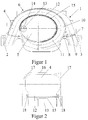
- Figure 1 shows a cross section of an air intake duct system 1 for an internal combustion engine with V-shaped cylinders, d. H. one inlet flange each 2, 3 is to be connected to rows of cylinders, not shown, of the internal combustion engine.
- a cut single intake duct 4 is shown, which is from a collective inlet duct 5 leads to the left row of cylinders via the left inlet flange 2.
- the air intake duct system 1 in the present exemplary embodiment is made of one made of light metal die-cast outer housing 6 formed from there are at least two housing parts 7, 8, which are connected to one another via the surface 9 are connected and have channel-forming adapters 10, 11 in their interior.
- an adjusting member 12 is arranged in the present air intake duct system 1, which is designed in the present case as a slat band.
- Figure 1 shows the single intake duct 4 with a long intake duct length. It should be clear that when the slat band 12 moves counterclockwise, the channel length continuously shortened.
- the slat band 12 is in the present embodiment by a gear 13, which in a known manner on a drive shaft 14 is arranged, driven.
- the gear 13 engages in formations 15, which are arranged on the underside of the lamellar belt 12. It should be clear that one for each slat band 12 of an intake duct Gear on the drive shaft 14 is assigned. Gears and drive shaft for the right individual intake ducts are not shown for the sake of simplicity.
- Figure 2 shows a single view of a single intake duct, which is essentially consists of a radial wall section 16 and two axial wall sections 17.
- the individual intake duct 4 is through the slat band 12 covered.
- the slat band 12 has in side walls Balls 18, which roll in the axial wall sections 17 and on them Way ensure a particularly smooth adjustment.
- FIG. 3 also shows a sectional view with a further embodiment of the Guide member 18, which in turn is movable on an axial wall portion 17 is mounted, in which case a Bowden cable 19 in the guide member 18th engages to drive the link belts 12.
- a Bowden cable 19 in the guide member 18th engages to drive the link belts 12.
- FIG. 4 shows a plan view of two lamellar belts 12 which are made from one another connected slats 20 are constructed. You can clearly see that through the Use of slats to achieve lateral offset, which means that variable, individual intake ducts to be set continuously a much larger one Design freedom is guaranteed.
Landscapes
- Engineering & Computer Science (AREA)
- Chemical & Material Sciences (AREA)
- Combustion & Propulsion (AREA)
- Mechanical Engineering (AREA)
- General Engineering & Computer Science (AREA)
- Manufacturing & Machinery (AREA)
- Physics & Mathematics (AREA)
- Geometry (AREA)
- Characterised By The Charging Evacuation (AREA)
Abstract
Description
- Figur 1
- Eine Schnittansicht eines erfindungsgemäßen Luftansaugkanalsystems,
- Figur 2
- einen Querschnitt durch ein Lamellenband mit Führungsorgan gemäß einer ersten Ausführungsform,
- Figur 3
- einen Querschnitt durch ein Lamellenband mit Führungsorganen gemäß einer zweiten Ausführungsform, und
- Figur 4
- eine Draufsicht eines Lamellenbandes.
Claims (5)
- Luftansaugkanalsystem für eine Brennkraftmaschine mit einem äußeren Gehäuse, das aus mindestens zwei Gehäuseteilen besteht, die über Dichtflächen miteinander verbunden sind, wobei das Gehäuse einen Sammeleinlaßkanal aufweist, von dem zu Zylindern der Brennkraftmaschine führende Einzelansaugkanäle abzweigen, die jeweils zwei axiale und einen radialen Wandbereich aufweisen, wobei diese Einzelansaugkanäle Verstellorgane zum Verändern der effektiven Ansaugkanallänge aufweisen, dadurch gekennzeichnet, daß die Verstellorgane durch Gliederbänder (12) gebildet sind, die sich an den axialen Wandbereichen (17) mittels Führungsorganen (18) abstützen.
- Luftansaugkanalsystem nach Anspruch 1, dadurch gekennzeichnet, daß die Gliederbänder (12) aus in quer zur Bewegungsrichtung verschiebbaren sowie gelenkig miteinander verbundenen Lamellen (20) bestehen.
- Luftansaugkanalsystem nach Anspruch 1 oder 2, dadurch gekennzeichnet, daß die Führungsorgane (18) aus in Seitenwänden der Glieder gelagerten Kugeln bestehen, die in den Wandbereichen (17) abrollen.
- Luftansaugkanalsystem nach Anspruch 3, dadurch gekennzeichnet, daß die Gliederbänder (12) über Zahnräder (13) antreibbar sind.
- Luftansaugkanalsystem nach Anspruch 3, dadurch gekennzeichnet, daß die Gliederbänder (12) über Bowdenzüge (19), die mit den Führungsorganen gekoppelt sind, antreibbar sind.
Applications Claiming Priority (2)
| Application Number | Priority Date | Filing Date | Title |
|---|---|---|---|
| DE10063207A DE10063207A1 (de) | 2000-12-19 | 2000-12-19 | Luftansaugkanalsystem für eine Brennkraftmaschine |
| DE10063207 | 2000-12-19 |
Publications (2)
| Publication Number | Publication Date |
|---|---|
| EP1217200A2 true EP1217200A2 (de) | 2002-06-26 |
| EP1217200A3 EP1217200A3 (de) | 2003-11-19 |
Family
ID=7667733
Family Applications (1)
| Application Number | Title | Priority Date | Filing Date |
|---|---|---|---|
| EP01120460A Withdrawn EP1217200A3 (de) | 2000-12-19 | 2001-08-28 | Luftansaugkanalsystem für eine Brennkraftmaschine |
Country Status (2)
| Country | Link |
|---|---|
| EP (1) | EP1217200A3 (de) |
| DE (1) | DE10063207A1 (de) |
Citations (1)
| Publication number | Priority date | Publication date | Assignee | Title |
|---|---|---|---|---|
| DE19756332A1 (de) | 1997-12-18 | 1999-06-24 | Pierburg Ag | Luftansaugkanalsystem für eine Brennkraftmaschine |
Family Cites Families (1)
| Publication number | Priority date | Publication date | Assignee | Title |
|---|---|---|---|---|
| DE19830508A1 (de) * | 1998-07-08 | 2000-01-13 | Pierburg Ag | Luftansaugkanalsystem für eine Brennkraftmaschine |
-
2000
- 2000-12-19 DE DE10063207A patent/DE10063207A1/de not_active Withdrawn
-
2001
- 2001-08-28 EP EP01120460A patent/EP1217200A3/de not_active Withdrawn
Patent Citations (1)
| Publication number | Priority date | Publication date | Assignee | Title |
|---|---|---|---|---|
| DE19756332A1 (de) | 1997-12-18 | 1999-06-24 | Pierburg Ag | Luftansaugkanalsystem für eine Brennkraftmaschine |
Also Published As
| Publication number | Publication date |
|---|---|
| EP1217200A3 (de) | 2003-11-19 |
| DE10063207A1 (de) | 2002-06-20 |
Similar Documents
| Publication | Publication Date | Title |
|---|---|---|
| DE102007040812B4 (de) | Kabelschutz- und -führungsvorrichtung vom Falttyp | |
| DE19943822B4 (de) | Strömungsleitanordnung, insbesondere Ausströmgrill für Lüftungs- und Klimaanlagen von Kraftfahrzeugen | |
| WO1999057457A1 (de) | Energieführungskette | |
| DE102020101678A1 (de) | Stellvorrichtung zum Verändern eines Massenstroms in einem Kraftfahrzeug | |
| EP1270286B1 (de) | Luftleitvorrichtung, insbesondere eines Fahrzeugs | |
| DE202017104198U1 (de) | Betätigungsvorrichtung mit Doppelketten-Anordnung | |
| EP3242056B1 (de) | Eingreifschutz für riemenantrieb | |
| DE102012112038B4 (de) | Schiebenocken für einen Ventiltrieb einer Brennkraftmaschine | |
| DE19524233A1 (de) | Kurzbauendes Sechsganggetriebe | |
| DE60208272T2 (de) | Betriebsmechanismus fuer zwei Plattenelemente fuer ein Schiebedach | |
| EP1998999B2 (de) | Lufteinlassbauteil für eine klimatisierungseinrichtung eines schienenfahrzeugs und mit dem lufteinlassbauteil ausgestattetes schienenfahrzeug | |
| DE69912554T2 (de) | Phasenverschobene Ketteneinheit | |
| DE3319950A1 (de) | Manuelle fernschaltvorrichtung | |
| DE102008004189A1 (de) | Luftausströmer | |
| EP1531290B1 (de) | Schalteinrichtung | |
| DE3339414A1 (de) | Wischblatt fuer fahrzeugscheiben | |
| EP0782939B1 (de) | Luftdüse | |
| DE102007025472A1 (de) | Luftleitvorrichtung für ein Fahrzeug | |
| DE102019129034B3 (de) | Kühlluftjalousie für ein Kraftfahrzeug, Verfahren zum Betrieb eines Kraftfahrzeugs, Kraftfahrzeug | |
| DE202004010293U1 (de) | Synchronisiereinrichtung für schaltbare Getriebe | |
| DE102004027914A1 (de) | Verschluss für mindestens eine Öffnung | |
| EP0900952B1 (de) | Riementrieb | |
| DE10063207A1 (de) | Luftansaugkanalsystem für eine Brennkraftmaschine | |
| DE102007005724A1 (de) | Luftausströmer | |
| DE10127650A1 (de) | Vorrichtung zur mechanischen Steuerung von Elementen einer Fahrzeugbelüftungsanlage |
Legal Events
| Date | Code | Title | Description |
|---|---|---|---|
| PUAI | Public reference made under article 153(3) epc to a published international application that has entered the european phase |
Free format text: ORIGINAL CODE: 0009012 |
|
| 17P | Request for examination filed |
Effective date: 20010828 |
|
| AK | Designated contracting states |
Kind code of ref document: A2 Designated state(s): AT BE CH CY DE DK ES FI FR GB GR IE IT LI LU MC NL PT SE TR |
|
| AX | Request for extension of the european patent |
Free format text: AL;LT;LV;MK;RO;SI |
|
| RAP1 | Party data changed (applicant data changed or rights of an application transferred) |
Owner name: PIERBURG GMBH |
|
| PUAL | Search report despatched |
Free format text: ORIGINAL CODE: 0009013 |
|
| AK | Designated contracting states |
Kind code of ref document: A3 Designated state(s): AT BE CH CY DE DK ES FI FR GB GR IE IT LI LU MC NL PT SE TR |
|
| AX | Request for extension of the european patent |
Extension state: AL LT LV MK RO SI |
|
| RIC1 | Information provided on ipc code assigned before grant |
Ipc: 7F 02B 27/02 B Ipc: 7F 02M 35/10 A |
|
| 17Q | First examination report despatched |
Effective date: 20040225 |
|
| AKX | Designation fees paid |
Designated state(s): DE ES FR GB IT |
|
| GRAP | Despatch of communication of intention to grant a patent |
Free format text: ORIGINAL CODE: EPIDOSNIGR1 |
|
| STAA | Information on the status of an ep patent application or granted ep patent |
Free format text: STATUS: THE APPLICATION IS DEEMED TO BE WITHDRAWN |
|
| 18D | Application deemed to be withdrawn |
Effective date: 20050202 |