EP1217093A1 - Densification de substrats poreux par infiltration chimique en phase vapeur - Google Patents
Densification de substrats poreux par infiltration chimique en phase vapeur Download PDFInfo
- Publication number
- EP1217093A1 EP1217093A1 EP01403282A EP01403282A EP1217093A1 EP 1217093 A1 EP1217093 A1 EP 1217093A1 EP 01403282 A EP01403282 A EP 01403282A EP 01403282 A EP01403282 A EP 01403282A EP 1217093 A1 EP1217093 A1 EP 1217093A1
- Authority
- EP
- European Patent Office
- Prior art keywords
- enclosure
- gas phase
- substrate
- flow
- substrates
- Prior art date
- Legal status (The legal status is an assumption and is not a legal conclusion. Google has not performed a legal analysis and makes no representation as to the accuracy of the status listed.)
- Granted
Links
- 239000000758 substrate Substances 0.000 title claims abstract description 139
- 238000000280 densification Methods 0.000 title claims description 22
- 230000008595 infiltration Effects 0.000 title claims description 20
- 238000001764 infiltration Methods 0.000 title claims description 20
- 239000000126 substance Substances 0.000 title claims description 15
- 239000012808 vapor phase Substances 0.000 title description 4
- 238000009434 installation Methods 0.000 claims description 26
- 238000000034 method Methods 0.000 claims description 19
- 230000008569 process Effects 0.000 claims description 13
- 230000004907 flux Effects 0.000 claims description 9
- 238000009826 distribution Methods 0.000 claims description 8
- 238000007599 discharging Methods 0.000 claims description 3
- 239000012071 phase Substances 0.000 description 66
- 239000007789 gas Substances 0.000 description 64
- OKTJSMMVPCPJKN-UHFFFAOYSA-N Carbon Chemical compound [C] OKTJSMMVPCPJKN-UHFFFAOYSA-N 0.000 description 15
- 239000002131 composite material Substances 0.000 description 10
- 239000011159 matrix material Substances 0.000 description 10
- 229910052799 carbon Inorganic materials 0.000 description 9
- 125000006850 spacer group Chemical group 0.000 description 7
- 239000007792 gaseous phase Substances 0.000 description 6
- 229910002804 graphite Inorganic materials 0.000 description 6
- 239000010439 graphite Substances 0.000 description 6
- VNWKTOKETHGBQD-UHFFFAOYSA-N methane Chemical compound C VNWKTOKETHGBQD-UHFFFAOYSA-N 0.000 description 6
- 230000012010 growth Effects 0.000 description 5
- 239000002243 precursor Substances 0.000 description 5
- 239000004071 soot Substances 0.000 description 5
- 230000015572 biosynthetic process Effects 0.000 description 4
- 239000000919 ceramic Substances 0.000 description 4
- 230000000295 complement effect Effects 0.000 description 4
- 238000000399 optical microscopy Methods 0.000 description 4
- 238000006243 chemical reaction Methods 0.000 description 3
- 230000007547 defect Effects 0.000 description 3
- 239000000835 fiber Substances 0.000 description 3
- 230000035800 maturation Effects 0.000 description 3
- 239000011819 refractory material Substances 0.000 description 3
- ATUOYWHBWRKTHZ-UHFFFAOYSA-N Propane Chemical compound CCC ATUOYWHBWRKTHZ-UHFFFAOYSA-N 0.000 description 2
- 239000000463 material Substances 0.000 description 2
- 230000003071 parasitic effect Effects 0.000 description 2
- 238000005086 pumping Methods 0.000 description 2
- 239000011347 resin Substances 0.000 description 2
- 229920005989 resin Polymers 0.000 description 2
- 239000007787 solid Substances 0.000 description 2
- 229920000049 Carbon (fiber) Polymers 0.000 description 1
- 238000002231 Czochralski process Methods 0.000 description 1
- XUIMIQQOPSSXEZ-UHFFFAOYSA-N Silicon Chemical compound [Si] XUIMIQQOPSSXEZ-UHFFFAOYSA-N 0.000 description 1
- 230000032683 aging Effects 0.000 description 1
- 150000001335 aliphatic alkanes Chemical class 0.000 description 1
- 150000001336 alkenes Chemical class 0.000 description 1
- 125000000217 alkyl group Chemical group 0.000 description 1
- 230000004075 alteration Effects 0.000 description 1
- 239000004917 carbon fiber Substances 0.000 description 1
- 238000003763 carbonization Methods 0.000 description 1
- 239000007795 chemical reaction product Substances 0.000 description 1
- 238000000354 decomposition reaction Methods 0.000 description 1
- 238000009792 diffusion process Methods 0.000 description 1
- 238000009730 filament winding Methods 0.000 description 1
- 210000002683 foot Anatomy 0.000 description 1
- 238000010438 heat treatment Methods 0.000 description 1
- 238000005470 impregnation Methods 0.000 description 1
- 230000006872 improvement Effects 0.000 description 1
- 239000007788 liquid Substances 0.000 description 1
- 238000004519 manufacturing process Methods 0.000 description 1
- 239000002184 metal Substances 0.000 description 1
- 239000005055 methyl trichlorosilane Substances 0.000 description 1
- JLUFWMXJHAVVNN-UHFFFAOYSA-N methyltrichlorosilane Chemical group C[Si](Cl)(Cl)Cl JLUFWMXJHAVVNN-UHFFFAOYSA-N 0.000 description 1
- 210000000452 mid-foot Anatomy 0.000 description 1
- 239000000203 mixture Substances 0.000 description 1
- 229910021421 monocrystalline silicon Inorganic materials 0.000 description 1
- 239000003345 natural gas Substances 0.000 description 1
- 238000006116 polymerization reaction Methods 0.000 description 1
- 239000001294 propane Substances 0.000 description 1
- 230000001681 protective effect Effects 0.000 description 1
- 239000002296 pyrolytic carbon Substances 0.000 description 1
- 239000003870 refractory metal Substances 0.000 description 1
- 229910052710 silicon Inorganic materials 0.000 description 1
- 239000010703 silicon Substances 0.000 description 1
- HBMJWWWQQXIZIP-UHFFFAOYSA-N silicon carbide Chemical compound [Si+]#[C-] HBMJWWWQQXIZIP-UHFFFAOYSA-N 0.000 description 1
- 229910010271 silicon carbide Inorganic materials 0.000 description 1
Images



Classifications
-
- C—CHEMISTRY; METALLURGY
- C04—CEMENTS; CONCRETE; ARTIFICIAL STONE; CERAMICS; REFRACTORIES
- C04B—LIME, MAGNESIA; SLAG; CEMENTS; COMPOSITIONS THEREOF, e.g. MORTARS, CONCRETE OR LIKE BUILDING MATERIALS; ARTIFICIAL STONE; CERAMICS; REFRACTORIES; TREATMENT OF NATURAL STONE
- C04B35/00—Shaped ceramic products characterised by their composition; Ceramics compositions; Processing powders of inorganic compounds preparatory to the manufacturing of ceramic products
- C04B35/71—Ceramic products containing macroscopic reinforcing agents
- C04B35/78—Ceramic products containing macroscopic reinforcing agents containing non-metallic materials
- C04B35/80—Fibres, filaments, whiskers, platelets, or the like
- C04B35/83—Carbon fibres in a carbon matrix
-
- C—CHEMISTRY; METALLURGY
- C23—COATING METALLIC MATERIAL; COATING MATERIAL WITH METALLIC MATERIAL; CHEMICAL SURFACE TREATMENT; DIFFUSION TREATMENT OF METALLIC MATERIAL; COATING BY VACUUM EVAPORATION, BY SPUTTERING, BY ION IMPLANTATION OR BY CHEMICAL VAPOUR DEPOSITION, IN GENERAL; INHIBITING CORROSION OF METALLIC MATERIAL OR INCRUSTATION IN GENERAL
- C23C—COATING METALLIC MATERIAL; COATING MATERIAL WITH METALLIC MATERIAL; SURFACE TREATMENT OF METALLIC MATERIAL BY DIFFUSION INTO THE SURFACE, BY CHEMICAL CONVERSION OR SUBSTITUTION; COATING BY VACUUM EVAPORATION, BY SPUTTERING, BY ION IMPLANTATION OR BY CHEMICAL VAPOUR DEPOSITION, IN GENERAL
- C23C16/00—Chemical coating by decomposition of gaseous compounds, without leaving reaction products of surface material in the coating, i.e. chemical vapour deposition [CVD] processes
- C23C16/04—Coating on selected surface areas, e.g. using masks
- C23C16/045—Coating cavities or hollow spaces, e.g. interior of tubes; Infiltration of porous substrates
-
- C—CHEMISTRY; METALLURGY
- C23—COATING METALLIC MATERIAL; COATING MATERIAL WITH METALLIC MATERIAL; CHEMICAL SURFACE TREATMENT; DIFFUSION TREATMENT OF METALLIC MATERIAL; COATING BY VACUUM EVAPORATION, BY SPUTTERING, BY ION IMPLANTATION OR BY CHEMICAL VAPOUR DEPOSITION, IN GENERAL; INHIBITING CORROSION OF METALLIC MATERIAL OR INCRUSTATION IN GENERAL
- C23C—COATING METALLIC MATERIAL; COATING MATERIAL WITH METALLIC MATERIAL; SURFACE TREATMENT OF METALLIC MATERIAL BY DIFFUSION INTO THE SURFACE, BY CHEMICAL CONVERSION OR SUBSTITUTION; COATING BY VACUUM EVAPORATION, BY SPUTTERING, BY ION IMPLANTATION OR BY CHEMICAL VAPOUR DEPOSITION, IN GENERAL
- C23C16/00—Chemical coating by decomposition of gaseous compounds, without leaving reaction products of surface material in the coating, i.e. chemical vapour deposition [CVD] processes
- C23C16/22—Chemical coating by decomposition of gaseous compounds, without leaving reaction products of surface material in the coating, i.e. chemical vapour deposition [CVD] processes characterised by the deposition of inorganic material, other than metallic material
- C23C16/26—Deposition of carbon only
-
- Y—GENERAL TAGGING OF NEW TECHNOLOGICAL DEVELOPMENTS; GENERAL TAGGING OF CROSS-SECTIONAL TECHNOLOGIES SPANNING OVER SEVERAL SECTIONS OF THE IPC; TECHNICAL SUBJECTS COVERED BY FORMER USPC CROSS-REFERENCE ART COLLECTIONS [XRACs] AND DIGESTS
- Y10—TECHNICAL SUBJECTS COVERED BY FORMER USPC
- Y10S—TECHNICAL SUBJECTS COVERED BY FORMER USPC CROSS-REFERENCE ART COLLECTIONS [XRACs] AND DIGESTS
- Y10S427/00—Coating processes
- Y10S427/10—Chemical vapor infiltration, i.e. CVI
Definitions
- the invention relates to the densification of hollow porous substrates. by chemical vapor infiltration, more particularly in isobaric, i.e. without pressure gradient between faces of substrates.
- a particular field of application of the invention is the production of hollow parts in composite material comprising a porous substrate densified by a matrix, in particular of hollow parts made of thermostructural composite material.
- hollow porous substrate is meant here a substrate having a hollow form with a full concave internal surface, i.e. free of holes, except the porous nature of the substrate.
- hollow shapes are shapes of spherical caps, shapes cylindrical or cylindro-conical closed at one end, forms of containers or bowls, cap shapes, not necessarily axisymmetric.
- hollow parts obtained by densification of such substrates are containers for the chemical industry or metallurgical, such as crucibles or support bowls crucibles, or protective bodies of spacecraft, such as nose forming heat shields.
- thermostructural composite material is meant here a composite material which at the same time has good properties mechanical, to constitute structural elements, and has the capacity to keep these properties at high temperatures.
- thermostructural composite materials are composite materials carbon / carbon (C / C) comprising a porous fiber substrate carbon densified by a carbon matrix, and composite materials with ceramic matrix (CMC) comprising a porous refractory substrate, by example of carbon or ceramic fibers, densified by a matrix ceramic.
- Densification of porous substrates by chemical infiltration in isobaric vapor phase is a well known process.
- the substrates to densify are placed in an enclosure and a reactive gas phase is allowed in the enclosure where temperature conditions prevail and controlled pressure such that the gaseous phase diffuses within the porosity of the substrates and forms a solid deposit therein constituting the matrix composite material by decomposition of a gaseous precursor or reaction between several gaseous precursors contained in the phase gas.
- the gaseous precursor is generally an alkane, an alkyl or an alkene, such as propane or methane or a mixture of the two.
- the gaseous precursor is methyltrichlorosilane.
- the reactive gas phase is admitted to a end of the enclosure while the gaseous effluents comprising the gas phase residue and possible reaction products are extracted at another end. Admission is advantageously performed through a preheating zone allowing to bring the gas phase at a temperature close to that of the substrates at densified.
- the substrates to be densified have a hollow shape such that defined above, with relatively deep concave parts, and especially when they are large enough, defects have have been observed by the inventors after densification by infiltration chemical vapor phase. These defects consist of variations in microstructure of the matrix material between different parts of the densified parts and in the formation of soot or growths undesirable on substrates.
- the object of the invention is to provide a process which does not have no such drawbacks, i.e. a process allowing a relatively homogeneous, flawless densification of substrates hollow in shape, even large.
- the flow of reactive gas phase admitted in the enclosure is distributed towards each face of the or each substrate arranged in the enclosure.
- the fraction of the total phase flux reactive gas traversing a face of the or each substrate arranged in the enclosure is at least 5%, or better yet, 10%.
- the inventors have observed that, by guiding a fraction of the flow gas phase in the enclosure to the interior of the substrates, a homogeneous densification is obtained, without the formation of soot or parasitic growths, including in the deepest areas hollow shapes. This can be explained by the fact that the guidance of the flux forces the gas phase to flow along all of the faces internal concaves of the substrates, without forming pockets of stagnation or vortex areas in which excessive maturation of the gas phase could occur.
- the guidance of part of the gas phase flow can be provided by a wall part which partially penetrates inside the volume delimited by the concave internal face of or each substrate, by example a part of a cylindrical wall which extends to the vicinity of the bottom of or each substrate.
- substrates of hollow form can be densified simultaneously in the enclosure by being arranged aligned with the general flow direction of the phase flow gas through the enclosure.
- the gas phase flow admitted in the enclosure is then distributed appropriately to supply each face of the substrates by a fraction of this flux.
- the invention also aims to provide an installation for densification by chemical vapor infiltration which allows the implementation of the process defined above, being adapted to the densification of hollow substrates.
- This object is achieved with an installation of the type comprising a enclosure having a side wall and first and second walls opposite ends to each other, means for admitting a phase reactive gas opening into the enclosure through the first wall end, means for discharging gaseous effluents opening into the enclosure through the second end wall, and at least one plate for supporting the substrate to be densified, installation comprising means for gas flow distribution and guidance to bring a fraction of gas flow gas phase allowed up to the location of each substrate in the enclosure and guide part of the gas phase flow brought to this location up to the interior of a volume delimited by an internal face concave of a substrate arranged in this location.
- the flow guiding means may include a part of cylindrical wall or a body having a plurality of passages through, the wall part or the body being arranged so as to penetrate at least partially into said volume of the substrate.
- the flow distribution means may include one or more several plates which are arranged transversely in the enclosure and which define flow distribution passages formed by openings made through the trays and spaces between the trays and a side wall of the enclosure.
- Figures 1 and 2 schematically show an enclosure 10 constituting a reaction chamber of an infiltration installation chemical vapor phase.
- the enclosure 10 has, in the example illustrated, a generally cylindrical shape with a vertical axis.
- a reactive gas phase is introduced into the enclosure by a pipe 12 which opens, for example at the center of the bottom wall 10 a of the enclosure 10.
- the gaseous effluents are extracted from the enclosure by a pipe 14 which opens at the center of the upper wall 10 b forming a cover opposite the bottom 10 a .
- Line 14 is connected to a pumping device (not shown).
- the gaseous phase passes through a preheating zone 16 consisting for example of horizontal perforated plates 18 which are arranged one above the other.
- the plates 18 are supported by the bottom 10 a of the enclosure by means of feet and spacers.
- the preheating zone is separated from the reaction chamber proper by a horizontal diffuser plate 20 which occupies substantially the entire section of the enclosure 10.
- the diffuser plate 20 is perforated and rests on the bottom 10 a of the enclosure by the 'midfoot.
- the above elements of the preheating zone are in refractory material, for example graphite.
- the heating inside the enclosure is produced by a graphite susceptor (or armature) electromagnetically coupled with an inductor (not shown) located outside the enclosure.
- the susceptor constitutes the side wall 10 c of the enclosure 10.
- the bottom 10 a and the cover 10 b are also made of graphite.
- the substrates shown have a bowl shape. It may for example be a bowl preform of composite material C / C intended to receive a crucible containing liquid silicon in an installation for drawing monocrystalline silicon ingots by the Czochralski process, or "CZ" process. Such bowls can have a diameter reaching or even exceeding 850 mm.
- the substrate or preform of the bowl is made of carbon fibers, by filament winding or draping of fibrous layers.
- the invention is not limited to the densification of such substrates and is aimed at the densification of all substrates of hollow form as defined at the head of this description.
- the substrates are arranged one above the other, being aligned in the general vertical direction of phase flow flow gas inside the enclosure, with their concave hollow faces turned down.
- Each substrate S 1 , S 2 , S 3 rests on a respective support plate 22 1 , 22 2 , 22 3 with interposition of shims 24 between the edge of the substrates and the upper faces of the plates.
- the support plate 22 1 rests by spacers 26 1 on the diffuser plate 20, while the plates 22 2 and 22 3 rest on the plates 22 1 and 22 2 by means of spacers 26 2 , 26 3 .
- the wedges 24 provide gaps between them allowing gas circulation. They can have the general shape of a ring sector and engage through their base in an annular groove formed in the upper face of the support plate. Each wedge 24 may have an annular external rim 24 a on which the rim of the substrate bears by its external contour. The wedges 24 then act as conformers by preventing deformation by expansion of the substrates.
- the shims 24 could also have an internal rim.
- Support plates, shims and spacers supporting the plates are made of a refractory material, for example a metal refractory or graphite.
- the support plates 22 1 , 22 2 and 22 3 also have a function of distributors of the flow of the gaseous phase admitted into the enclosure and coming from the preheating zone.
- the plates are made of a gas-tight material, have an orifice respectively 28 1 , 28 2 , 28 3 in their center and provide a respective annular space at their periphery 30 1 , 30 2 , 30 3 with the side wall 10 c of the enclosure.
- the orifices 28 1 , 28 2 , 28 3 and the passages defined by the annular spaces 30 1 , 30 2 , 30 3 distribute the flow of the gas phase so that a fraction of the fresh gas phase admitted into the enclosure at each location of a substrate in the enclosure and on each side of a substrate disposed at this location. This fraction is at least 5%, preferably at least 10% by volume.
- each of the internal and external faces of the substrates S 1 , S 2 and S 3 therefore preferably receives at least 10%, and better still approximately 1/6 th of the flow of fresh gas phase admitted in the pregnant.
- the passage 30 1 receives the complement of the total flow of gas phase admitted with respect to that which is received by the internal face of the substrate S 1 via the orifice 28 1 .
- the passage 30 2 receives the complement of the flow of admitted gas phase having passed through the passage 30 1 , with respect to what is received by the external face of the substrate S 1 and what is received by the internal face of the substrate S 2 via the orifice 28 2 .
- the passage 30 3 receives the complement of the flow of admitted gas phase having passed through the passage 30 2 , with respect to what is received by the external face of the substrate S 2 and what is received by the internal face of the substrate S 3 via the orifice 28 3 . This remaining fraction of the admitted gas phase flow passing through the passage 30 3 feeds the external face of the substrate S 3 .
- Each fraction of gas phase flow passing through an orifice 28 1 , 28 2 , 28 3 is guided towards the internal face of the bottom of the corresponding substrate by means of a respective guide wall 32 1 , 32 2 , 32 3 , provided at each location of a substrate in the enclosure, and constituting a tool for guiding the flow of gas phase for the associated substrate.
- Each of these guide walls has a cylindrical shape, or section of pipe, which is connected to a respective orifice 28 1 , 28 2 , 28 3 and protrudes above the corresponding support plate, inside the volume. delimited by the substrate.
- Each guide wall thus brings a fraction of flux directly in the vicinity of the bottom region of the corresponding substrate.
- Each guide wall is interrupted at a distance from the internal surface of the corresponding substrate such that an annular gap is formed with it providing a passage section at least equal to that of the orifice formed in the support plate.
- the guide walls are made of a refractory material of preferably gas tight, for example of a refractory metal or graphite, or in pyrographite sheets, as produced under the name "SIGRAFLEX®" by the German company SIGRI GmbH.
- the guide walls 32 1 , 32 2 , 32 3 Thanks to the guide walls 32 1 , 32 2 , 32 3 , a fraction of the flow of gas phase admitted is forced to fully lick the internal faces of the substrates S 1 , S 2 , S 3 and to flow along them. without leaving dead volume and without creating vortices. It can thus be guaranteed that the residence time of the gas phase remains at any point below a limit value beyond which the maturation of the gas phase may become excessive and cause the formation of parasitic deposits.
- the total residence time of the gaseous phase in the enclosure that is to say the time elapsing between its admission and its evacuation must remain limited.
- the residence time is for example generally controlled to remain less than 2 s, typically between 1 s and 1.5 s.
- the chemical vapor infiltration process is isobaric type, i.e. without pressure gradient between the faces internal and external substrates.
- the number of substrates present in the enclosure can of course be different from three, even unique, while allowing for the possibility of distribute the gas phase flow so that a significant fraction feeds each side of the substrates.
- Multiple gas phase intake ports in the enclosure, several orifices for discharging gaseous effluents out of the enclosure and several preheating zones can then be provided, each in front of a set of substrates and support trays.
- substrates of different hollow shapes or different dimensions can be densified simultaneously in one same enclosure, possibly adapting the shapes and dimensions means for guiding the flow towards the interior of the substrates.
- FIGS. 3 and 4 illustrate another alternative embodiment of the invention.
- the installation of FIGS. 3 and 4 differs from that of FIGS. 1 and 2 in that the support plates 122 1 , 122 2 , 122 3 do not rest on spacers but on cleats or pegs 126 1 , 126 2 , 126 3 engaged in the side wall 10 c of the enclosure, in the manner of shelves.
- the support plates can then occupy almost all enclosure section 10.
- each support plate has a central orifice 128 1 , 128 2 , 128 3 to which is connected a tool for guiding reactive gas phase flow, formed by a cylindrical wall 132 1 , 132 2 , 132 3 .
- Lights 130 1 , 130 2 , 130 3 are formed in the plates along an annular zone of these, outside the vertical alignment of the edges of the substrates S 1 , S 2 , S 3 , in order to d offer direct passages to fractions of gas phase flow admitted into the enclosure through the planes of the plates, in the same way as the passages 30 1 , 30 2 , 30 3 of FIGS. 1 and 2.
- FIGS. 5 and 6 illustrate yet another alternative embodiment of the invention.
- the installation in FIGS. 5 and 6 differs from that in FIGS. 3 and 4 in that the support plates 222 1 , 222 2 , 222 3 , which rest on cleats 226 1 , 226 2 , 226 3 , each carry a plurality of substrates, in this case three substrates such as the substrates S 3 , S ' 3 , S " 3 for the plate 222 3 .
- Each plate for example the plate 222 3 , has several orifices 228 3 , 228 ' 3 and 228 " 3 for directing a fraction of gas phase flow towards each internal concave face of the substrates supported by the plate.
- a guide tool formed by a respective cylindrical guide wall 232 3 , 232 ′ 3 , 232 " 3 connects to each orifice and projects inside the volume delimited by the corresponding substrate in order to guide the fraction of flux to the vicinity of the bottom of the substrate .
- Lights 230 3 are formed in the tray 222 3 around the locations of the substrates S 3 , S ' 3 , S " 3 in order to allow direct crossing of the plane of the tray 222 3 by part of the flow of gas phase admitted into the enclosure, around each substrate.
- the plates 222 1 and 222 2 are produced in the same way as the plate 222 3 with orifices such as 228 1 , 228 ′ 1 , 228 2 and 228 ′ 2 to which guide walls 232 1 , 232 ′ 1 are connected, and 232 2 , 232 ' 2 , and with lights 230 1 and 230 2 .
- the dimensions of the orifices and lights formed in the support plates are chosen to ensure the desired distribution of the flow of fresh gas phase admitted in enclosure 10 towards the faces of substrates.
- exhaust gas exhaust pipes 214, 214 ', 214 are preferably provided which are assembled outside of the enclosure and open therein facing the tops of the substrates arranged on the upper plate, in order to ensure a complete course of the outer faces of these substrates by gas phase flow.
- the substrates are arranged in the infiltration enclosure with their internal faces concave directed downwards, i.e. directed against the direction general flow of reactive gas phase flow in the enclosure.
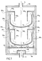
- a reverse arrangement of the substrates may be adopted, as shown in figure 7.
- FIG. 7 differs from that of FIG. 1, in particular in that the substrates S 1 , S 2 are arranged in the enclosure 10 with their concave internal faces directed upwards.
- Each substrate S 1 , S 2 rests by the external face of its bottom on a plurality of (at least three) wedges or studs 324 1 , 324 2 .
- the pads 324 1 are supported by a plate 316 providing preheating and diffusion functions of the gaseous phase admitted into the enclosure by the pipe 12 opening out at the bottom of the enclosure, the inlet opening of the gaseous phase being overcome of a flow distribution cap 318.
- the pads 324 2 are fixed on a respective support plate 322 1 which rests on the diffuser plate 316 by means of spacers 326 2 .
- the support plate 322 1 has a wide central opening 328 1 while providing an annular space 330 1 at its periphery with the side wall 10 c of the enclosure.
- the plate 322 1 surmounts the substrate S 1 by providing an annular space 331 1 with the upper edge of the substrate.
- An upper plate 322 2 supported by spacers 326 2 is disposed above the substrate S 2 in the same manner as the plate 322 1 with respect to the substrate S 1 .
- the plate 322 2 has a large central opening 328 2 and provides an annular space 330 2 with the side wall of the enclosure and an annular space 331 2 with the upper edge of the substrate S 2 .
- the reactive gas phase flow admitted into the enclosure is distributed through the spaces 330 1 , 330 2 and 331 2 so that a fraction of this flow feeds each face of the substrates.
- the fraction of flux passing through the spaces 331 1 , 331 2 is guided towards the concave internal face of the substrates S 1 , S 2 by means of tools formed by respective guide walls 332 1 , 332 2 .
- the guide walls have, for example, the shape of a cylinder, or of section of pipe, which are supported by the plates 322 1 , 322 2 by connecting at their upper part to the edges of the openings 328 1 , 328 2 .
- Each guide wall penetrates a certain distance into the internal part of a respective substrate to cause the flow admitted at the periphery to flow towards the bottom of the substrate before flowing upward through the pipe defined by the wall guide (see arrows in figure 7).
- the residual gas phase flowing through the opening 328 2 of the upper plate is discharged through line 24 which opens through the cover 10b of the enclosure.
- the guide walls 332 1 , 332 2 thus force a fraction of the reactive gas phase flow allowed to lick the internal faces of the substrates S 1 , S 2 and to flow along them without leaving dead volume and without create swirls.
- Figure 7 shows only two substrate locations, the number of these locations could of course be more than two, by having more than two substrates on top of each other or forming several juxtaposed sets of substrates arranged one above the other others as in Figure 5.
- a substrate S 1 has been shown supported by a plate 422 1 by means of studs or shims 424 1 .
- the substrate S 1 is arranged with its concave internal face directed downwards and rests by its edge on the wedges 424 1 .
- a gas phase flow flows in an annular space 430 1 around the substrate S 1 and through the plate 422 1 to supply the internal face of the substrate S 1 .
- the plate 422 1 in its part located opposite the internal face of the substrate S 1 , has a plurality of passages, or perforations 423 1 and supports a guide tool 432 1 .
- the tool 432 1 is a block, for example made of graphite, having a shape similar and complementary to that of the internal volume of the substrate S 1 , but of smaller size in order to provide a space between the external face of the block and the internal face of the substrate.
- the block is pierced with a multitude of passages 433 1 which brings the gas phase passing through the plate 422 1 to the vicinity of the internal face of the substrate, so that this internal face is traversed by the flow of gas phase without leaving any dead volumes.
- the method according to the invention can of course be implemented on substrates of different dimensions housed simultaneously inside the enclosure.
- Substrates consisting of bowl preforms have been densified by means of an installation as shown in Figure 7.
- the substrates were made up of two-dimensional fiber strata carbon draped over a form and consolidated by impregnation with a resin followed by polymerization and carbonization of the resin.
- Densification of substrates by a carbon matrix pyrolytic was carried out by admitting a phase in the enclosure gaseous comprising natural gas, or methane, as a precursor gaseous pyrolytic carbon.
- the temperature and pressure in the enclosure were kept substantially constant during the densification, at values equal to approximately 1000 ° C and 1.5 kPa.
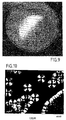
- the internal face of the C / C composite material bowls obtained has a beautiful appearance, as shown in Figures 9 and 10, the FIG. 10 being an image obtained by optical microscopy, with 440 magnification, of a fraction of the surface of the bottom of a bowl after densification.
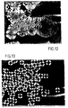
- Figures 10 and 13 do not reveal growths and soot such as those visible in FIG. 12, confirm that the process according to the invention makes it possible, basically of hollow parts of substrate, the same quality as on substrates having no hollow parts.
Landscapes
- Chemical & Material Sciences (AREA)
- Engineering & Computer Science (AREA)
- Organic Chemistry (AREA)
- Chemical Kinetics & Catalysis (AREA)
- Materials Engineering (AREA)
- Metallurgy (AREA)
- Mechanical Engineering (AREA)
- General Chemical & Material Sciences (AREA)
- Ceramic Engineering (AREA)
- Composite Materials (AREA)
- Manufacturing & Machinery (AREA)
- Structural Engineering (AREA)
- Inorganic Chemistry (AREA)
- Chemical Vapour Deposition (AREA)
- Ceramic Products (AREA)
Abstract
Description
- la figure 1 est une vue très schématique partielle en élévation et en coupe d'une installation d'infiltration chimique en phase vapeur selon un premier mode de mise en oeuvre de l'invention ;
- la figure 2 est une demi-vue en coupe de dessus selon le plan II-II de la figure 1 ;
- la figure 3 est une vue très schématique partielle en élévation et en coupe d'une installation d'infiltration chimique en phase vapeur selon un deuxième mode de mise en oeuvre de l'invention ;
- la figure 4 est une demi-vue en coupe de dessus selon le plan IV-IV de la figure 3 ;
- la figure 5 est une vue très schématique partielle en élévation et en coupe selon les plans V-V de la figure 6 d'une installation d'infiltration chimique en phase vapeur selon un troisième mode de mise en oeuvre de l'invention ;
- la figure 6 est une vue en coupe de dessus selon le plan VI-VI de la figure 5 ;
- la figure 7 est une vue très schématique partielle en élévation et en coupe d'une installation d'infiltration chimique en phase vapeur selon un quatrième mode de mise en oeuvre de l'invention ;
- la figure 8 est une vue partielle en coupe montrant une variante de réalisation d'un outillage de guidage du flux de phase gazeuse réactive vers la face interne concave d'un substrat ;
- la figure 9 est une photographie montrant l'aspect général de surface d'une face concave de substrat densifié avec le procédé conforme à l'invention ;
- la figure 10 est une photographie obtenue en microscopie optique montrant une fraction de surface de la face concave du substrat densifié de la figure 9 ;
- la figure 11 est une vue très schématique d'une installation d'infiltration chimique en phase vapeur selon l'art antérieur ; et
- les figures 12 et 13 sont des photographies obtenues en microscopie optique montrant l'état de surface d'échantillons, après densification au moyen de l'installation de la figure 11.
Claims (12)
- Procédé de densification de substrats poreux de forme creuse par infiltration chimique en phase vapeur en mode isobare, comprenant la disposition d'au moins un substrat dans une enceinte et l'admission dans l'enceinte d'une phase gazeuse réactive,
caractérisé en ce que le flux de phase gazeuse réactive admise dans l'enceinte est en partie guidé par un outillage jusqu'à l'intérieur du volume délimité par une face interne concave du ou de chaque substrat de forme creuse de sorte que ladite face interne concave soit en totalité parcourue par une fraction du flux total de la phase gazeuse admise. - Procédé selon la revendication 1, caractérisé en ce que le flux de phase gazeuse réactive admise dans l'enceinte est réparti vers chaque face du ou de chaque substrat disposé dans l'enceinte.
- Procédé selon l'une quelconque des revendications 1 et 2, caractérisé en ce que la fraction du flux total de phase gazeuse réactive parcourant une face du ou de chaque substrat disposé dans l'enceinte est d'au moins 5 %.
- Procédé selon l'une quelconque des revendications 1 et 2, caractérisé en ce que la fraction du flux total de phase gazeuse réactive parcourant une face du ou de chaque substrat disposé dans l'enceinte est d'au moins 10 %.
- Procédé selon l'une quelconque des revendications 1 à 4, caractérisé en ce que l'on densifie simultanément plusieurs substrats disposés dans l'enceinte en étant alignés dans la direction générale d'écoulement du flux de phase gazeuse à travers l'enceinte.
- Procédé selon l'une quelconque des revendications 1 à 5, caractérisé en ce que le guidage d'une partie du flux de phase gazeuse est assuré par une partie de paroi qui pénètre partiellement à l'intérieur du volume délimité par la face interne concave du ou de chaque substrat.
- Procédé selon la revendication 6, caractérisé en ce que le flux de phase gazeuse est en partie guidé par une partie de paroi cylindrique jusqu'au voisinage du fond du ou de chaque substrat.
- Procédé selon l'une quelconque des revendications 1 à 5, caractérisé en ce que le guidage d'une partie de flux de phase gazeuse est assuré par des passages formés à travers un corps logé à l'intérieur du volume délimité par la face interne concave du ou de chaque substrat.
- Installation pour la densification de substrats poreux de forme creuse par infiltration chimique en phase vapeur, comprenant une enceinte ayant une paroi latérale et une première et une deuxième paroi d'extrémité opposées l'une à l'autre, des moyens d'admission d'une phase gazeuse réactive débouchant dans l'enceinte à travers la première paroi d'extrémité, des moyens d'évacuation d'effluents gazeux s'ouvrant dans l'enceinte à travers la deuxième paroi d'extrémité, et au moins un plateau de support de substrat à densifier,
installation caractérisée en ce qu'elle comprend des moyens de répartition et guidage de flux gazeux pour amener une fraction de flux de phase gazeuse réactive admise jusqu'à l'emplacement de chaque substrat dans l'enceinte et guider une partie du flux de phase gazeuse amené à cet emplacement jusqu'à l'intérieur d'un volume délimité par une face interne concave d'un substrat disposé en cet emplacement. - Installation selon la revendication 9, caractérisée en ce que les moyens de guidage de flux comportent un outillage de guidage constitué par une partie de paroi cylindrique disposée de manière à pénétrer au moins en partie dans ledit volume du substrat.
- Installation selon la revendication 9, caractérisée en ce que les moyens de guidage de flux comportent un outillage de guidage constitué par corps présentant une pluralité de passages traversants et disposé de manière à pénétrer au moins en partie dans ledit volume du substrat.
- Installation selon l'une quelconque des revendications 9 à 11, caractérisée en ce que les moyens de répartition de flux comprennent un ou plusieurs plateaux qui sont disposés transversalement dans l'enceinte et qui définissent des passages de répartition de flux formés par des ouvertures réalisées à travers les plateaux et des espaces ménagés entre les plateaux et une paroi latérale de l'enceinte.
Applications Claiming Priority (2)
| Application Number | Priority Date | Filing Date | Title |
|---|---|---|---|
| FR0016615A FR2818291B1 (fr) | 2000-12-19 | 2000-12-19 | Densification de substrats poreux creux par infiltration chimique en phase vapeur |
| FR0016615 | 2000-12-19 |
Publications (2)
| Publication Number | Publication Date |
|---|---|
| EP1217093A1 true EP1217093A1 (fr) | 2002-06-26 |
| EP1217093B1 EP1217093B1 (fr) | 2011-02-09 |
Family
ID=8857896
Family Applications (1)
| Application Number | Title | Priority Date | Filing Date |
|---|---|---|---|
| EP01403282A Expired - Lifetime EP1217093B1 (fr) | 2000-12-19 | 2001-12-18 | Densification de substrats poreux creux par infiltration chimique en phase vapeur |
Country Status (5)
| Country | Link |
|---|---|
| US (1) | US6942893B2 (fr) |
| EP (1) | EP1217093B1 (fr) |
| JP (1) | JP4263398B2 (fr) |
| DE (1) | DE60144007D1 (fr) |
| FR (1) | FR2818291B1 (fr) |
Cited By (5)
| Publication number | Priority date | Publication date | Assignee | Title |
|---|---|---|---|---|
| EP1285976A3 (fr) * | 2001-08-20 | 2004-12-22 | Goodrich Corporation | Outillages pour procédés CVI/CVD |
| EP2480702A4 (fr) * | 2009-09-22 | 2013-10-30 | 3M Innovative Properties Co | Articles comprenant un substrat poreux sur lequel est appliquée une couche conforme |
| WO2014170586A1 (fr) * | 2013-04-18 | 2014-10-23 | Herakles | Outillage de maintien, chargement et installation pour la densification de préformes poreuses de révolution |
| CN108218461A (zh) * | 2018-01-24 | 2018-06-29 | 航天睿特碳材料有限公司 | 一种单晶炉用碳/碳热场结构产品的快速cvd致密方法 |
| CN118756117A (zh) * | 2024-08-02 | 2024-10-11 | 苏州耀德半导体有限公司 | 一种便于分流的cvd设备用沉积室 |
Families Citing this family (31)
| Publication number | Priority date | Publication date | Assignee | Title |
|---|---|---|---|---|
| US7476419B2 (en) * | 1998-10-23 | 2009-01-13 | Goodrich Corporation | Method for measurement of weight during a CVI/CVD process |
| FR2834713B1 (fr) * | 2002-01-15 | 2004-04-02 | Snecma Moteurs | Procede et installation pour la densification de substrats par infiltration chimique en phase vapeur |
| DE10357698A1 (de) * | 2003-12-09 | 2005-07-14 | Schunk Kohlenstofftechnik Gmbh | Träger für zu behandelnde Gegenstände sowie Verfahren zur Herstellung eines solchen |
| US7335397B2 (en) * | 2004-02-16 | 2008-02-26 | Goodrich Corporation | Pressure gradient CVI/CVD apparatus and method |
| KR101029428B1 (ko) | 2004-06-30 | 2011-04-14 | 엘지디스플레이 주식회사 | 액정표시장치의 램프 구동장치 |
| FR2881145B1 (fr) * | 2005-01-24 | 2007-11-23 | Snecma Propulsion Solide Sa | Procede d'infiltration chimique en phase gazeuse pour la densification de substrats poreux par du carbone pyrolytique |
| FR2882064B1 (fr) | 2005-02-17 | 2007-05-11 | Snecma Propulsion Solide Sa | Procede de densification de substrats poreux minces par infiltration chimique en phase vapeur et dispositif de chargement de tels substrats |
| US20080232424A1 (en) * | 2007-03-23 | 2008-09-25 | Honeywell International Inc. | Hearth plate including side walls defining a processing volume |
| US20110064891A1 (en) * | 2009-09-16 | 2011-03-17 | Honeywell International Inc. | Methods of rapidly densifying complex-shaped, asymmetrical porous structures |
| FR2953553B1 (fr) * | 2009-12-09 | 2012-02-03 | Snecma | Aube de turbine de turbomachine en composite a matrice ceramique avec evidements realises par usinage |
| BR112014010116A8 (pt) * | 2011-10-31 | 2017-06-20 | 3M Innovative Properties Co | métodos para a aplicação de um revestimento a um substrato em forma cilíndrica |
| US11326255B2 (en) * | 2013-02-07 | 2022-05-10 | Uchicago Argonne, Llc | ALD reactor for coating porous substrates |
| US9523149B2 (en) | 2013-03-14 | 2016-12-20 | Rolls-Royce Corporation | Rapid ceramic matrix composite production method |
| US9605345B2 (en) * | 2013-08-23 | 2017-03-28 | Taiwan Semiconductor Manufacturing Co., Ltd. | Vertical furnace for improving wafer uniformity |
| US9852905B2 (en) * | 2014-01-16 | 2017-12-26 | Taiwan Semiconductor Manufacturing Company, Ltd. | Systems and methods for uniform gas flow in a deposition chamber |
| JP6020483B2 (ja) * | 2014-02-14 | 2016-11-02 | トヨタ自動車株式会社 | 表面処理装置と表面処理方法 |
| US10648075B2 (en) * | 2015-03-23 | 2020-05-12 | Goodrich Corporation | Systems and methods for chemical vapor infiltration and densification of porous substrates |
| WO2017033053A1 (fr) | 2015-08-21 | 2017-03-02 | Flisom Ag | Source d'évaporation linéaire homogène |
| TWI624554B (zh) * | 2015-08-21 | 2018-05-21 | 弗里松股份有限公司 | 蒸發源 |
| FR3084672B1 (fr) * | 2018-08-03 | 2020-10-16 | Safran Ceram | Procede de densification par infiltration chimique en phase gazeuse de substrats annulaires poreux |
| US10837109B2 (en) * | 2018-11-15 | 2020-11-17 | United Technologies Corporation | CVI/CVD matrix densification process and apparatus |
| CN110963815B (zh) * | 2019-10-10 | 2022-01-28 | 福建康碳复合材料科技有限公司 | 一种制备大尺寸碳/碳发热体的工艺方法 |
| US11111578B1 (en) | 2020-02-13 | 2021-09-07 | Uchicago Argonne, Llc | Atomic layer deposition of fluoride thin films |
| FI129868B (en) * | 2021-03-30 | 2022-10-14 | Beneq Oy | A gas feeding cup and a gas manifold assembly |
| US12065738B2 (en) | 2021-10-22 | 2024-08-20 | Uchicago Argonne, Llc | Method of making thin films of sodium fluorides and their derivatives by ALD |
| FR3130276A1 (fr) * | 2021-12-15 | 2023-06-16 | Safran Ceramics | Installation de traitement thermochimique et procédé de fabrication d’une pièce de friction en matériau composite |
| US11932941B1 (en) | 2021-12-29 | 2024-03-19 | Rolls-Royce High Temperature Composites, Inc. | Load assemblies for loading parts in a furnace |
| US12000046B1 (en) * | 2021-12-29 | 2024-06-04 | Rolls-Royce High Temperature Composites, Inc. | Load assemblies for loading parts in a furnace |
| US12078417B1 (en) | 2021-12-29 | 2024-09-03 | Rolls-Royce High Temperature Composites, Inc. | Load assemblies for loading parts in a furnace |
| US11901169B2 (en) | 2022-02-14 | 2024-02-13 | Uchicago Argonne, Llc | Barrier coatings |
| CN115181960B (zh) * | 2022-06-23 | 2023-11-24 | 西安鑫垚陶瓷复合材料股份有限公司 | 一种薄壁尖锥回转件的cvi导流装置及其使用方法 |
Citations (4)
| Publication number | Priority date | Publication date | Assignee | Title |
|---|---|---|---|---|
| US4609562A (en) * | 1984-12-20 | 1986-09-02 | Westinghouse Electric Corp. | Apparatus and method for depositing coating onto porous substrate |
| JPH0782058A (ja) * | 1993-09-09 | 1995-03-28 | Nissan Motor Co Ltd | 炭素繊維/炭素複合材の炭化ケイ素被覆形成方法 |
| US5904957A (en) * | 1995-04-18 | 1999-05-18 | Societe Europeenne De Propulsion | Vapour phase chemical infiltration process for densifying porous substrates disposed in annular stacks |
| FR2801304A1 (fr) * | 1999-11-24 | 2001-05-25 | Snecma | Procede de fabrication d'un bol en materiau composite thermostructural, notamment pour une installation de production de silicium monocristallin |
Family Cites Families (6)
| Publication number | Priority date | Publication date | Assignee | Title |
|---|---|---|---|---|
| DE2739258C2 (de) * | 1977-08-31 | 1985-06-20 | Wacker-Chemitronic Gesellschaft für Elektronik-Grundstoffe mbH, 8263 Burghausen | Verfahren zur Aufbringung einer Siliciumcarbid und Siliciumnitrid enthaltenden Schutzschicht auf Kohlenstofformkörper |
| US4741925A (en) * | 1987-09-14 | 1988-05-03 | Gte Products Corporation | Method of forming silicon nitride coating |
| US5911824A (en) * | 1997-12-16 | 1999-06-15 | Saint-Gobain Industrial Ceramics, Inc. | Method for growing crystal |
| US6669988B2 (en) * | 2001-08-20 | 2003-12-30 | Goodrich Corporation | Hardware assembly for CVI/CVD processes |
| JP4218853B2 (ja) * | 1999-03-03 | 2009-02-04 | 東海カーボン株式会社 | 単結晶引き上げ用炭素質ルツボとその製造方法 |
| JP2003514760A (ja) * | 1999-11-24 | 2003-04-22 | スネクマ・モートゥール | 熱構造複合材の容器を製造する方法、その方法により得られた容器、およびその容器のるつぼ支持体としての使用 |
-
2000
- 2000-12-19 FR FR0016615A patent/FR2818291B1/fr not_active Expired - Fee Related
-
2001
- 2001-12-18 JP JP2001384189A patent/JP4263398B2/ja not_active Expired - Fee Related
- 2001-12-18 DE DE60144007T patent/DE60144007D1/de not_active Expired - Lifetime
- 2001-12-18 EP EP01403282A patent/EP1217093B1/fr not_active Expired - Lifetime
- 2001-12-18 US US10/024,272 patent/US6942893B2/en not_active Expired - Lifetime
Patent Citations (4)
| Publication number | Priority date | Publication date | Assignee | Title |
|---|---|---|---|---|
| US4609562A (en) * | 1984-12-20 | 1986-09-02 | Westinghouse Electric Corp. | Apparatus and method for depositing coating onto porous substrate |
| JPH0782058A (ja) * | 1993-09-09 | 1995-03-28 | Nissan Motor Co Ltd | 炭素繊維/炭素複合材の炭化ケイ素被覆形成方法 |
| US5904957A (en) * | 1995-04-18 | 1999-05-18 | Societe Europeenne De Propulsion | Vapour phase chemical infiltration process for densifying porous substrates disposed in annular stacks |
| FR2801304A1 (fr) * | 1999-11-24 | 2001-05-25 | Snecma | Procede de fabrication d'un bol en materiau composite thermostructural, notamment pour une installation de production de silicium monocristallin |
Non-Patent Citations (1)
| Title |
|---|
| PATENT ABSTRACTS OF JAPAN vol. 1995, no. 06 31 July 1995 (1995-07-31) * |
Cited By (6)
| Publication number | Priority date | Publication date | Assignee | Title |
|---|---|---|---|---|
| EP1285976A3 (fr) * | 2001-08-20 | 2004-12-22 | Goodrich Corporation | Outillages pour procédés CVI/CVD |
| EP2480702A4 (fr) * | 2009-09-22 | 2013-10-30 | 3M Innovative Properties Co | Articles comprenant un substrat poreux sur lequel est appliquée une couche conforme |
| WO2014170586A1 (fr) * | 2013-04-18 | 2014-10-23 | Herakles | Outillage de maintien, chargement et installation pour la densification de préformes poreuses de révolution |
| FR3004732A1 (fr) * | 2013-04-18 | 2014-10-24 | Herakles | Outillage de maintien, chargement et installation pour la densification de preformes poreuses de revolution |
| CN108218461A (zh) * | 2018-01-24 | 2018-06-29 | 航天睿特碳材料有限公司 | 一种单晶炉用碳/碳热场结构产品的快速cvd致密方法 |
| CN118756117A (zh) * | 2024-08-02 | 2024-10-11 | 苏州耀德半导体有限公司 | 一种便于分流的cvd设备用沉积室 |
Also Published As
| Publication number | Publication date |
|---|---|
| JP2002241938A (ja) | 2002-08-28 |
| US20020076491A1 (en) | 2002-06-20 |
| FR2818291A1 (fr) | 2002-06-21 |
| JP4263398B2 (ja) | 2009-05-13 |
| FR2818291B1 (fr) | 2003-11-07 |
| DE60144007D1 (de) | 2011-03-24 |
| US6942893B2 (en) | 2005-09-13 |
| EP1217093B1 (fr) | 2011-02-09 |
Similar Documents
| Publication | Publication Date | Title |
|---|---|---|
| EP1217093B1 (fr) | Densification de substrats poreux creux par infiltration chimique en phase vapeur | |
| EP1466031B1 (fr) | Procede et installation pour la densification de substrats par infiltration chimique en phase vapeur | |
| EP1851358B1 (fr) | Procede de densification de substrats poreux minces par infiltration chimique en phase vapeur et dispositif de chargement de tels substrats | |
| EP0821744B1 (fr) | Procede d'infiltration chimique en phase vapeur pour la densification de substrats poreux disposes en piles annulaires | |
| EP2870272B1 (fr) | Dispositif de chargement et installation pour la densification de préformes poreuses tronconiques empilables. | |
| WO2002070775A1 (fr) | Procede pour la densification par infiltration chimique en phase vapeur de substrats poreux ayant un passage central | |
| EP3833800B1 (fr) | Procédé de densification par infiltration chimique en phase gazeuse de substrats annulaire poreux | |
| EP2875167B1 (fr) | Installation d'infiltration chimique en phase vapeur à haute capacité de chargement | |
| EP0946461B1 (fr) | Densification de substrats poreux disposes en piles annulaires par infiltration chimique en phase vapeur a gradient de temperature | |
| FR2980486A1 (fr) | Dispositif de chargement pour la densification par infiltration chimique en phase vapeur en flux dirige de substrats poreux de forme tridimensionnelle | |
| FR3050812A1 (fr) | Outillage de chargement a grande modularite | |
| FR2732962A1 (fr) | Procede pour l'infiltration chimique en phase vapeur d'un materiau compose de carbone et de silicium et/ou bore | |
| EP4479575A1 (fr) | Procede de densification par infiltration chimique en phase gazeuse avec des plateaux monopiles pour un flux semi-force | |
| EP4479574B1 (fr) | Procédé de densification cvi avec outillage de plateaux multipiles pour flux semi-force | |
| FR3157384A1 (fr) | Procédé de fabrication d'une aube par infiltration chimique en phase vapeur | |
| WO2020002841A1 (fr) | Procede de densification par infiltration chimique en phase gazeuse de substrats annulaires poreux | |
| WO2023118701A1 (fr) | Conformateur multiple pour infiltration en phase gazeuse |
Legal Events
| Date | Code | Title | Description |
|---|---|---|---|
| PUAI | Public reference made under article 153(3) epc to a published international application that has entered the european phase |
Free format text: ORIGINAL CODE: 0009012 |
|
| AK | Designated contracting states |
Kind code of ref document: A1 Designated state(s): AT BE CH CY DE DK ES FI FR GB GR IE IT LI LU MC NL PT SE TR |
|
| AX | Request for extension of the european patent |
Free format text: AL;LT;LV;MK;RO;SI |
|
| 17P | Request for examination filed |
Effective date: 20021220 |
|
| AKX | Designation fees paid |
Designated state(s): DE FR GB |
|
| RAP1 | Party data changed (applicant data changed or rights of an application transferred) |
Owner name: SNECMA |
|
| RAP1 | Party data changed (applicant data changed or rights of an application transferred) |
Owner name: SNECMA PROPULSION SOLIDE |
|
| 17Q | First examination report despatched |
Effective date: 20091125 |
|
| GRAP | Despatch of communication of intention to grant a patent |
Free format text: ORIGINAL CODE: EPIDOSNIGR1 |
|
| GRAS | Grant fee paid |
Free format text: ORIGINAL CODE: EPIDOSNIGR3 |
|
| GRAA | (expected) grant |
Free format text: ORIGINAL CODE: 0009210 |
|
| AK | Designated contracting states |
Kind code of ref document: B1 Designated state(s): DE FR GB |
|
| REG | Reference to a national code |
Ref country code: GB Ref legal event code: FG4D Free format text: NOT ENGLISH |
|
| REF | Corresponds to: |
Ref document number: 60144007 Country of ref document: DE Date of ref document: 20110324 Kind code of ref document: P |
|
| REG | Reference to a national code |
Ref country code: DE Ref legal event code: R096 Ref document number: 60144007 Country of ref document: DE Effective date: 20110324 |
|
| PLBE | No opposition filed within time limit |
Free format text: ORIGINAL CODE: 0009261 |
|
| STAA | Information on the status of an ep patent application or granted ep patent |
Free format text: STATUS: NO OPPOSITION FILED WITHIN TIME LIMIT |
|
| 26N | No opposition filed |
Effective date: 20111110 |
|
| REG | Reference to a national code |
Ref country code: DE Ref legal event code: R097 Ref document number: 60144007 Country of ref document: DE Effective date: 20111110 |
|
| REG | Reference to a national code |
Ref country code: DE Ref legal event code: R082 Ref document number: 60144007 Country of ref document: DE Representative=s name: CBDL PATENTANWAELTE, DE |
|
| REG | Reference to a national code |
Ref country code: DE Ref legal event code: R081 Ref document number: 60144007 Country of ref document: DE Owner name: HERAKLES, FR Free format text: FORMER OWNER: SNECMA PROPULSION SOLIDE, LE HAILLAN, FR Effective date: 20130114 Ref country code: DE Ref legal event code: R082 Ref document number: 60144007 Country of ref document: DE Representative=s name: CBDL PATENTANWAELTE, DE Effective date: 20130114 |
|
| REG | Reference to a national code |
Ref country code: GB Ref legal event code: 732E Free format text: REGISTERED BETWEEN 20130221 AND 20130227 |
|
| REG | Reference to a national code |
Ref country code: FR Ref legal event code: TP Owner name: HERAKLES, FR Effective date: 20130513 |
|
| REG | Reference to a national code |
Ref country code: FR Ref legal event code: PLFP Year of fee payment: 15 |
|
| REG | Reference to a national code |
Ref country code: FR Ref legal event code: PLFP Year of fee payment: 16 |
|
| PGFP | Annual fee paid to national office [announced via postgrant information from national office to epo] |
Ref country code: DE Payment date: 20161121 Year of fee payment: 16 Ref country code: GB Payment date: 20161128 Year of fee payment: 16 |
|
| REG | Reference to a national code |
Ref country code: FR Ref legal event code: PLFP Year of fee payment: 17 |
|
| REG | Reference to a national code |
Ref country code: DE Ref legal event code: R119 Ref document number: 60144007 Country of ref document: DE |
|
| GBPC | Gb: european patent ceased through non-payment of renewal fee |
Effective date: 20171218 |
|
| PG25 | Lapsed in a contracting state [announced via postgrant information from national office to epo] |
Ref country code: DE Free format text: LAPSE BECAUSE OF NON-PAYMENT OF DUE FEES Effective date: 20180703 |
|
| PG25 | Lapsed in a contracting state [announced via postgrant information from national office to epo] |
Ref country code: GB Free format text: LAPSE BECAUSE OF NON-PAYMENT OF DUE FEES Effective date: 20171218 |
|
| PGFP | Annual fee paid to national office [announced via postgrant information from national office to epo] |
Ref country code: FR Payment date: 20181220 Year of fee payment: 18 |
|
| PG25 | Lapsed in a contracting state [announced via postgrant information from national office to epo] |
Ref country code: FR Free format text: LAPSE BECAUSE OF NON-PAYMENT OF DUE FEES Effective date: 20191231 |