EP1216896A2 - Flange shaped discharge opening for an airbag module - Google Patents
Flange shaped discharge opening for an airbag module Download PDFInfo
- Publication number
- EP1216896A2 EP1216896A2 EP01310559A EP01310559A EP1216896A2 EP 1216896 A2 EP1216896 A2 EP 1216896A2 EP 01310559 A EP01310559 A EP 01310559A EP 01310559 A EP01310559 A EP 01310559A EP 1216896 A2 EP1216896 A2 EP 1216896A2
- Authority
- EP
- European Patent Office
- Prior art keywords
- air bag
- opening
- flange
- end portion
- retainer
- Prior art date
- Legal status (The legal status is an assumption and is not a legal conclusion. Google has not performed a legal analysis and makes no representation as to the accuracy of the status listed.)
- Withdrawn
Links
Images


Classifications
-
- B—PERFORMING OPERATIONS; TRANSPORTING
- B60—VEHICLES IN GENERAL
- B60R—VEHICLES, VEHICLE FITTINGS, OR VEHICLE PARTS, NOT OTHERWISE PROVIDED FOR
- B60R21/00—Arrangements or fittings on vehicles for protecting or preventing injuries to occupants or pedestrians in case of accidents or other traffic risks
- B60R21/02—Occupant safety arrangements or fittings, e.g. crash pads
- B60R21/16—Inflatable occupant restraints or confinements designed to inflate upon impact or impending impact, e.g. air bags
- B60R21/20—Arrangements for storing inflatable members in their non-use or deflated condition; Arrangement or mounting of air bag modules or components
- B60R21/217—Inflation fluid source retainers, e.g. reaction canisters; Connection of bags, covers, diffusers or inflation fluid sources therewith or together
- B60R21/2171—Inflation fluid source retainers, e.g. reaction canisters; Connection of bags, covers, diffusers or inflation fluid sources therewith or together specially adapted for elongated cylindrical or bottle-like inflators with a symmetry axis perpendicular to the main direction of bag deployment, e.g. extruded reaction canisters
Definitions
- the present invention relates to an air bag apparatus for a vehicle, and more particularly to an air bag apparatus for a vehicle which reduces an influence of heat applied to the air bag.
- An air bag apparatus for securing a safety of a passenger at a time of colliding is mounted in a vehicle, for example, to a front passenger's seat side of an instrument panel.
- the air bag apparatus is structured such that when the vehicle collides, an air bag pushes and breaks a lid on an upper surface of the instrument panel in a moment of time so as to deploy, thereby preventing an upper body of the passenger from colliding with the instrument panel or a front glass.
- a folded air bag is stored in a case having an open end in an upper portion, and an opening is provided on a bottom surface of the case.
- a retainer having an opening is mounted from the above to a peripheral edge of the opening.
- An end portion of the air bag is held between the retainer and the peripheral edge of the opening so as to be fixed thereto.
- An inflator is mounted facing to an inner side of the air bag, and gas discharged out from the inflator is introduced to an inner portion of the air bag from the opening so as to deploy the air bag upward.
- the end portion of the air bag is in a state to be confronted with the opening, in a case where said gas with high temperature and high pressure is discharged from the inflator to the opening, there is a possibility that the end portion of the air bag is influenced with the heat of said discharged gas (deterioration of fibers by the heat). Therefore the end portion of the air bag (especially in a vicinity of a mounting port) needs a special reinforcement by comparison with the other portions so that a manufacture of the air bag requires difficult labors.
- the present invention is performed from a view of the problem of the related art and provides an air bag apparatus for a vehicle whose end is hardly influenced by a heat of discharged gas.
- a folded air bag is stored in a case having an open end, and an opening is provided on a surface opposite to the open end of the case.
- a peripheral edge of an opening is formed as a flange protruding toward an inside of the case, and a retainer having a plurality of rectangular openings is mounted from the inside of the case.
- An end portion of the air bag is held between the retainer and the peripheral edge of the opening so as to be fixed thereto.
- An inflator is mounted facing to an inner side of the air bag, and the gas discharged out from the inflator is introduced to an inner portion of the air bag so as to deploy the air bag through the open end.
- the flange extends higher than the end portion of the air bag
- the flange protects the end portion of the air bag from a heat of said discharged gas , it is not necessary to reinforce the end portion of the air bag excessively and it is easy to manufacture the air bag. Further, since the flange has an operation of introducing said discharged gas into the inner portion of the air bag without disturbing a flow current of said gas, it is possible to more securely achieve a smooth expansion of the air bag. Further, since the flange increases a rigidity of the peripheral edge portion of the opening, it is possible to make the case thin, so that it is possible to lighten the air bag apparatus.
- the retainer comprises a covering surface fitted to the flange and the end portion of the air bag is curved along the flange and is fixed not only between the retainer and the peripheral edge of the opening but also between the retainer and the flange.
- the end portion of the air bag is held in a curved state, since an area in which the end portion of the air bag is held is relatively large and the end portion of the air bag is held in a curved state, the end portion of the air bag is hard to be drawn out even when the tension is applied.
- a plurality of gas injection holes of the inflator exists near a center of the opening of the case. Since it is possible to make the opening and the retainer smaller, it is possible to make the air bag apparatus compact.
- a bracket comprising one or more grooves on an inner surface thereof is fixed to the lower surface of the case so that the bracket and the retainer surround the inflator. Said discharged gas is effectively conducted to the air bag.
- Fig. 1 shows an instrument panel 1 placed in a front portion within a passenger's compartment.
- a lid 3 breakable in a shape of letter 'H' is fitted to an aperture 2 on an upper surface of the instrument panel 1.
- a case 4 formed by a sheet metal is fixed to an inner portion of the aperture 2.
- the case 4 is formed in a box shape having an open upper end.
- An opening 5 is pierced rectangularly on a bottom surface of the case 4.
- An edge of the opening 5 is bent toward so as to form a flange 6.
- a folded air bag 7 is stored in an inner portion of the case 4.
- a retainer 8 is mounted to a peripheral edge of the opening 5 from the inside of the case 4.
- Three rectangular openings 8a are opened to an upper side of the retainer 8.
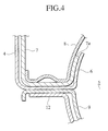
- An end portion 7a of the air bag 7 is held between the retainer 8 and the peripheral edge of the opening 5 so as to be fixed. Further, the end portion 7a of the air bag 7 is held between the flange 6 and the retainer 8 along a longitudinal line of the opening 5 so as to be fixed. Since the flange 6 extends higher than the end portion 7a of the air bag, the end portion 7a of the air bag 7 is not directly exposed to said discharged gas.
- the end portion 7a of the air bag 7 is also held between the flange 6 and the retainer 8, an area in which the end portion 7a of the air bag is held is increased, so that the air bag 7 can be more securely fixed. Since the portion held by the flange 6 and the retainer 8 is bent from the portion held by the peripheral edge of the opening 5 and the retainer 8, the end portion 7a of the air bag 7 is harder to be drawn out.
- An inflator 10 is arranged so as to be faced to an inner side of the air bag 7 and is fixed by a bracket 9.
- the inflator 10 is formed in a cylindrical shape, and is arranged in parallel to a longitudinal direction of the opening 5.
- the inflator 10 is provided with a plurality of gas injection holes 11 substantially in a center in a longitudinal direction thereof.
- the gas injection holes 11 are positioned substantially at a center with respect to the opening 5.
- the bracket 9 is curved so as to surround a lower side of the inflator 10 and comprises a plurality of grooves toward the opening 5 on an inner surface thereof. Said gas going to flow around the lower side of the inflator 10 is introduced to the opening 5 by the bracket 9.
- a fixing metal fitting 12 is further mounted to a lower side of the bracket 9, and is further fixed to a vehicle body reinforcing member (not shown).
- Another reinforcing member 13 is also mounted to a side surface of the case 4.
- the case 4, the retainer 8, the bracket 9 and the fixing metal fitting 12 mentioned above are fastened by a weld bolt 14 previously attached to the retainer 8 and a nut 15.
- a fastening force of the nut 15 corresponds to a force holding the end portion 7a of the air bag 7.
- a signal is transmitted to the air bag apparatus mentioned above from a collision sensor (not shown). Then, a combustible reagent within the inflator 10 burns, and gas having a high temperature and a high pressure is discharged out from the gas injection holes 11. Said discharged gas is introduced into an inner portion of the air bag 7 through the opening 8a of the retainer 8 so as to deploy the air bag 7. The deployed air bag 7 pushes and breaks the lid 3 so as to deploy within the passenger's compartment. The deployed air bag 7 receives and holds an upper body of the passenger going to tilt down to a forward portion of the vehicle.
- the flange 6 protects the end portion 7a of the air bag 7 from said discharged gas, it is possible to preserve the end portion 7a of the air bag 7 from the influence of heat. Further, the end portion 7a of the air bag 7 is fixed not only between the retainer 8 and the peripheral edge of the opening 5 but also between the retainer 8 and the flange 6. Since the area in which the end portion 7a of the air bag 7 is held is relatively large and the end portion 7a of the air bag 7 is held in the curved state, the end portion 7a is hard to be drawn even when the tension is applied. Accordingly, it is not necessary to reinforce the end portion 7a of the air bag 7 severely and it is easy to manufacture the air bag 7.
- the flange 6 Since the flange 6 has an operation of introducing said discharged gas into the inner portion of the air bag 7 without disturbing the flow current of the gas, it is possible to more securely obtain a smooth expansion of the air bag 7. Further, since the flange 6 increases a rigidity of the peripheral edge of the opening 5, it is possible to make the case 4 thin, so that it is possible to lighten the air bag apparatus.
- the gas injection holes 11 of the inflator 10 are arranged near the center of the opening 5 in the case 4. Since the opening 5 and the retainer 8 can be made smaller, it is possible to make the air bag apparatus compact.
Abstract
Description
- The present invention relates to an air bag apparatus for a vehicle, and more particularly to an air bag apparatus for a vehicle which reduces an influence of heat applied to the air bag.
- An air bag apparatus for securing a safety of a passenger at a time of colliding is mounted in a vehicle, for example, to a front passenger's seat side of an instrument panel. The air bag apparatus is structured such that when the vehicle collides, an air bag pushes and breaks a lid on an upper surface of the instrument panel in a moment of time so as to deploy, thereby preventing an upper body of the passenger from colliding with the instrument panel or a front glass. As a related art, there has been disclosed Japanese Patent Application Laid-Open No. 11-321510.
- According to the related art mentioned above, a folded air bag is stored in a case having an open end in an upper portion, and an opening is provided on a bottom surface of the case. A retainer having an opening is mounted from the above to a peripheral edge of the opening. An end portion of the air bag is held between the retainer and the peripheral edge of the opening so as to be fixed thereto. An inflator is mounted facing to an inner side of the air bag, and gas discharged out from the inflator is introduced to an inner portion of the air bag from the opening so as to deploy the air bag upward.
- In a case of the related art, because the end portion of the air bag is in a state to be confronted with the opening, in a case where said gas with high temperature and high pressure is discharged from the inflator to the opening, there is a possibility that the end portion of the air bag is influenced with the heat of said discharged gas (deterioration of fibers by the heat). Therefore the end portion of the air bag (especially in a vicinity of a mounting port) needs a special reinforcement by comparison with the other portions so that a manufacture of the air bag requires difficult labors.
- The present invention is performed from a view of the problem of the related art and provides an air bag apparatus for a vehicle whose end is hardly influenced by a heat of discharged gas.
- According to a first aspect of the present invention, a folded air bag is stored in a case having an open end, and an opening is provided on a surface opposite to the open end of the case. A peripheral edge of an opening is formed as a flange protruding toward an inside of the case, and a retainer having a plurality of rectangular openings is mounted from the inside of the case. An end portion of the air bag is held between the retainer and the peripheral edge of the opening so as to be fixed thereto. An inflator is mounted facing to an inner side of the air bag, and the gas discharged out from the inflator is introduced to an inner portion of the air bag so as to deploy the air bag through the open end. The flange extends higher than the end portion of the air bag
- Since the flange protects the end portion of the air bag from a heat of said discharged gas , it is not necessary to reinforce the end portion of the air bag excessively and it is easy to manufacture the air bag. Further, since the flange has an operation of introducing said discharged gas into the inner portion of the air bag without disturbing a flow current of said gas, it is possible to more securely achieve a smooth expansion of the air bag. Further, since the flange increases a rigidity of the peripheral edge portion of the opening, it is possible to make the case thin, so that it is possible to lighten the air bag apparatus.
- According to a second aspect of the present invention, in addition to the structure according to the first aspect mentioned above, the retainer comprises a covering surface fitted to the flange and the end portion of the air bag is curved along the flange and is fixed not only between the retainer and the peripheral edge of the opening but also between the retainer and the flange.
- According to the second aspect of the present invention, since an area in which the end portion of the air bag is held is relatively large and the end portion of the air bag is held in a curved state, the end portion of the air bag is hard to be drawn out even when the tension is applied.
- According to a third aspect of the present invention, in addition to the structure according to the first aspect mentioned above, a plurality of gas injection holes of the inflator exists near a center of the opening of the case. Since it is possible to make the opening and the retainer smaller, it is possible to make the air bag apparatus compact.
- According to a fourth aspect of the present invention, in addition to the structure according to the first aspect mentioned above, a bracket comprising one or more grooves on an inner surface thereof is fixed to the lower surface of the case so that the bracket and the retainer surround the inflator. Said discharged gas is effectively conducted to the air bag.
- The present invention will now be described, by way of example, with reference to the accompanying drawings, in which:
- Fig. 1 is a perspective view showing a state of attaching an air bag apparatus according to the present invention to an instrument panel;
- Fig. 2 is a cross sectional view of an air bag apparatus according to an embodiment of the present invention along a line II-II in Fig. 1;
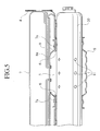
- Fig. 3 is an exploded perspective view of the air bag apparatus according to the embodiment of the present invention;
- Fig. 4 is an enlarged sectional view of a portion shown by a circle IV in Fig. 2; and
- Fig. 5 is a cross sectional view along a line V-V in Fig. 2.
-
- Fig. 1 shows an
instrument panel 1 placed in a front portion within a passenger's compartment. Alid 3 breakable in a shape of letter 'H' is fitted to anaperture 2 on an upper surface of theinstrument panel 1. - A
case 4 formed by a sheet metal is fixed to an inner portion of theaperture 2. Thecase 4 is formed in a box shape having an open upper end. Anopening 5 is pierced rectangularly on a bottom surface of thecase 4. An edge of the opening 5 is bent toward so as to form aflange 6. - A folded
air bag 7 is stored in an inner portion of thecase 4. Aretainer 8 is mounted to a peripheral edge of theopening 5 from the inside of thecase 4. Threerectangular openings 8a are opened to an upper side of theretainer 8. Anend portion 7a of theair bag 7 is held between theretainer 8 and the peripheral edge of the opening 5 so as to be fixed. Further, theend portion 7a of theair bag 7 is held between theflange 6 and theretainer 8 along a longitudinal line of theopening 5 so as to be fixed. Since theflange 6 extends higher than theend portion 7a of the air bag, theend portion 7a of theair bag 7 is not directly exposed to said discharged gas. - Since the
end portion 7a of theair bag 7 is also held between theflange 6 and theretainer 8, an area in which theend portion 7a of the air bag is held is increased, so that theair bag 7 can be more securely fixed. Since the portion held by theflange 6 and theretainer 8 is bent from the portion held by the peripheral edge of theopening 5 and theretainer 8, theend portion 7a of theair bag 7 is harder to be drawn out. - An
inflator 10 is arranged so as to be faced to an inner side of theair bag 7 and is fixed by abracket 9. Theinflator 10 is formed in a cylindrical shape, and is arranged in parallel to a longitudinal direction of theopening 5. Theinflator 10 is provided with a plurality ofgas injection holes 11 substantially in a center in a longitudinal direction thereof. Thegas injection holes 11 are positioned substantially at a center with respect to the opening 5. Thebracket 9 is curved so as to surround a lower side of theinflator 10 and comprises a plurality of grooves toward theopening 5 on an inner surface thereof. Said gas going to flow around the lower side of theinflator 10 is introduced to theopening 5 by thebracket 9. - A
fixing metal fitting 12 is further mounted to a lower side of thebracket 9, and is further fixed to a vehicle body reinforcing member (not shown). Another reinforcingmember 13 is also mounted to a side surface of thecase 4. - The
case 4, theretainer 8, thebracket 9 and thefixing metal fitting 12 mentioned above are fastened by aweld bolt 14 previously attached to theretainer 8 and anut 15. A fastening force of thenut 15 corresponds to a force holding theend portion 7a of theair bag 7. - When the vehicle collides, a signal is transmitted to the air bag apparatus mentioned above from a collision sensor (not shown). Then, a combustible reagent within the
inflator 10 burns, and gas having a high temperature and a high pressure is discharged out from thegas injection holes 11. Said discharged gas is introduced into an inner portion of theair bag 7 through the opening 8a of theretainer 8 so as to deploy theair bag 7. The deployedair bag 7 pushes and breaks thelid 3 so as to deploy within the passenger's compartment. The deployedair bag 7 receives and holds an upper body of the passenger going to tilt down to a forward portion of the vehicle. - According to the embodiment of the present invention as mentioned above, since the
flange 6 protects theend portion 7a of theair bag 7 from said discharged gas, it is possible to preserve theend portion 7a of theair bag 7 from the influence of heat. Further, theend portion 7a of theair bag 7 is fixed not only between theretainer 8 and the peripheral edge of theopening 5 but also between theretainer 8 and theflange 6. Since the area in which theend portion 7a of theair bag 7 is held is relatively large and theend portion 7a of theair bag 7 is held in the curved state, theend portion 7a is hard to be drawn even when the tension is applied. Accordingly, it is not necessary to reinforce theend portion 7a of theair bag 7 severely and it is easy to manufacture theair bag 7. Since theflange 6 has an operation of introducing said discharged gas into the inner portion of theair bag 7 without disturbing the flow current of the gas, it is possible to more securely obtain a smooth expansion of theair bag 7. Further, since theflange 6 increases a rigidity of the peripheral edge of theopening 5, it is possible to make thecase 4 thin, so that it is possible to lighten the air bag apparatus. - According to the embodiment of the present invention as mentioned above, further, the gas injection holes 11 of the inflator 10 are arranged near the center of the
opening 5 in thecase 4. Since theopening 5 and theretainer 8 can be made smaller, it is possible to make the air bag apparatus compact. - The contents of Japanese Patent Application No. 2000 - 385734 (filed December 19, 2000) are incorporated herein by reference.
- Although the invention has been described above by reference to certain embodiments of the invention, the invention is not limited to the embodiments described above. Modifications and variations of the embodiments described above will occur to those skilled in the art, in light of the above teachings.
Claims (8)
- An air bag apparatus for a vehicle comprising:wherein the flange (6) extends higher than the end portion (7a) of the air bag (7).a case (4) comprising an open end, a surface opposite to the open end comprising an opening (5) and a flange (6) standing inward from a peripheral edge of the opening (5);a folded air bag (7) stored in the case (4), having an end portion (7a) connected to the inner peripheral edge of the opening (5); anda retainer (8) fixed to the inner peripheral edge of the opening (5) holding the end portion (7a) of the air bag (7) therebetween,an inflator (10) facing to the inner side of the air bag (7) for discharging gas to deploy the air bag (7);
- An air bag apparatus for a vehicle according to claim 1,
wherein the retainer (8) comprises a covering surface fitted to the flange (6). - An air bag apparatus for a vehicle according to claim 2,
wherein the end portion (7a) of the air bag (7) is curved along the flange (6) and is further held between the covering surface of the retainer (8) and the flange (6). - An air bag apparatus for a vehicle according to any one of claim 1 to 3,
wherein the inflator (10) comprises one or more gas injection holes (11) positioned substantially at a center of the opening (5). - An air bag apparatus for a vehicle according to any one of claim 1 to 4, further comprising:a bracket (9) fixed to an outer side of the surface opposite to the open end of the case (4) so that the bracket (9) and the retainer (8) surround the inflator (10).
- An air bag apparatus for vehicle according to claim 5,
wherein the bracket (9) further comprises one or more grooves on a surface opposite to the inflator (10) thereof so that said gas is conducted to the opening (5). - An air bag apparatus for vehicle according to any one of claim 1, 2, 4, 5 and 6,
wherein the end portion (7a) of the air bag (7) is curved along the flange (6). - An air bag apparatus comprising: an air bag (7) having an edge portion (7a) defining an opening disposed opposite an inflator (10) for inflating the air bag; a housing (4) for the air bag and a holder (8) for holding the edge portion to the housing; wherein the housing comprises a shield (6) for shielding the edge portion from inflation gas.
Applications Claiming Priority (2)
| Application Number | Priority Date | Filing Date | Title |
|---|---|---|---|
| JP2000385734 | 2000-12-19 | ||
| JP2000385734A JP3884910B2 (en) | 2000-12-19 | 2000-12-19 | Airbag device for vehicle |
Publications (2)
| Publication Number | Publication Date |
|---|---|
| EP1216896A2 true EP1216896A2 (en) | 2002-06-26 |
| EP1216896A3 EP1216896A3 (en) | 2004-02-04 |
Family
ID=18852950
Family Applications (1)
| Application Number | Title | Priority Date | Filing Date |
|---|---|---|---|
| EP01310559A Withdrawn EP1216896A3 (en) | 2000-12-19 | 2001-12-18 | Flange shaped discharge opening for an airbag module |
Country Status (3)
| Country | Link |
|---|---|
| US (1) | US6820892B2 (en) |
| EP (1) | EP1216896A3 (en) |
| JP (1) | JP3884910B2 (en) |
Families Citing this family (5)
| Publication number | Priority date | Publication date | Assignee | Title |
|---|---|---|---|---|
| US6802526B2 (en) * | 2002-10-08 | 2004-10-12 | Autoliv Asp, Inc. | Inflatable restraint module |
| KR100529496B1 (en) * | 2003-10-17 | 2005-11-21 | 현대모비스 주식회사 | Passenger air bag system of vehicle |
| JP2007203869A (en) * | 2006-02-01 | 2007-08-16 | Toyoda Gosei Co Ltd | Airbag device |
| DE102006057503A1 (en) * | 2006-12-06 | 2008-06-12 | GM Global Technology Operations, Inc., Detroit | An air bag assembly |
| US9925946B2 (en) * | 2015-12-04 | 2018-03-27 | Fca Us Llc | Low mass passenger airbag |
Citations (1)
| Publication number | Priority date | Publication date | Assignee | Title |
|---|---|---|---|---|
| JPH11321510A (en) | 1998-05-18 | 1999-11-24 | Takata Kk | Air bag device |
Family Cites Families (16)
| Publication number | Priority date | Publication date | Assignee | Title |
|---|---|---|---|---|
| US5332256A (en) * | 1992-02-24 | 1994-07-26 | Morton International, Inc. | Continuous circumference diffuser reaction canister |
| DE4233751C2 (en) * | 1992-10-07 | 1994-12-22 | Daimler Benz Ag | Occupant restraint system |
| US5518266A (en) * | 1994-10-20 | 1996-05-21 | Trw Inc. | Vehicle safety apparatus including inflatable restraint |
| US5564730A (en) * | 1995-06-27 | 1996-10-15 | Trw Inc. | Folded air bag |
| DE19528754A1 (en) * | 1995-08-04 | 1997-02-06 | Trw Repa Gmbh | Airbag restraint module |
| JPH09142242A (en) * | 1995-11-27 | 1997-06-03 | Toyoda Gosei Co Ltd | Air bag device for passenger's seat |
| DE29606830U1 (en) * | 1996-04-15 | 1996-08-08 | Trw Repa Gmbh | Assembly consisting of a steering wheel, a steering shaft and an airbag module |
| US5718447A (en) * | 1996-09-10 | 1998-02-17 | Morton International, Inc. | Pressure relief in airbag module reaction canisters |
| DE29706246U1 (en) * | 1997-04-08 | 1997-08-07 | Trw Repa Gmbh | Airbag module for a vehicle occupant restraint system |
| DE19801125A1 (en) * | 1998-01-14 | 1999-07-15 | Breed Automotive Tech | Airbag module |
| US6149192A (en) * | 1998-08-11 | 2000-11-21 | Trw Inc. | Inflator having gas deflector flanges |
| DE19857213A1 (en) * | 1998-08-11 | 2000-02-24 | Linde & Wiemann Gmbh Kg | Airbag housing for occupant restraint system of motor vehicle has retaining rods with prismatic cross section form-lock fitted in cut-outs between housing and retaining plate |
| US6155599A (en) * | 1998-08-11 | 2000-12-05 | Trw Vehicle Safety Systems Inc. | Retaining ring with gas diffuser |
| US6082765A (en) * | 1998-11-10 | 2000-07-04 | Trw Vehicle Safety Systems Inc. | Air bag module with fluid venting |
| DE69915230T2 (en) * | 1998-12-21 | 2005-03-03 | Toyoda Gosei Co., Ltd. | Car interior part with airbag cover part |
| JP4120132B2 (en) * | 1999-08-19 | 2008-07-16 | タカタ株式会社 | Air bag device and its case |
-
2000
- 2000-12-19 JP JP2000385734A patent/JP3884910B2/en not_active Expired - Fee Related
-
2001
- 2001-12-18 EP EP01310559A patent/EP1216896A3/en not_active Withdrawn
- 2001-12-19 US US10/026,277 patent/US6820892B2/en not_active Expired - Fee Related
Patent Citations (1)
| Publication number | Priority date | Publication date | Assignee | Title |
|---|---|---|---|---|
| JPH11321510A (en) | 1998-05-18 | 1999-11-24 | Takata Kk | Air bag device |
Also Published As
| Publication number | Publication date |
|---|---|
| US6820892B2 (en) | 2004-11-23 |
| US20020043787A1 (en) | 2002-04-18 |
| JP3884910B2 (en) | 2007-02-21 |
| EP1216896A3 (en) | 2004-02-04 |
| JP2002187513A (en) | 2002-07-02 |
Similar Documents
| Publication | Publication Date | Title |
|---|---|---|
| EP0958970B1 (en) | Airbag device | |
| US5183288A (en) | Air bag device for automobile | |
| US8240706B2 (en) | Airbag arranged on the vehicle roof | |
| US7185912B2 (en) | Knee protection airbag device | |
| US5348339A (en) | Air bag module with cover | |
| US7669884B2 (en) | Air bag device | |
| US20030001366A1 (en) | Assembly consisting of a car body, a windshield, a dashboard and an airbag module | |
| KR20010049742A (en) | Seamless passenger side inflatable restraint system | |
| EP0899171B1 (en) | Head-protecting air bag device | |
| JPH115505A (en) | Air bag device for front-seat passenger | |
| JP2002524353A (en) | Air bag module | |
| EP1216896A2 (en) | Flange shaped discharge opening for an airbag module | |
| US6663141B2 (en) | Inflatable safety restraint assembly and methods of installing such an inflatable safety restraint assembly | |
| JP2010018099A (en) | Front passenger seat airbag device | |
| GB2262071A (en) | An air bag device for a passenger | |
| CN116997489A (en) | Airbag mounting structure | |
| JP7234857B2 (en) | air bag device | |
| JPH09323609A (en) | Automobile seat with air bag device | |
| EP1669256B1 (en) | Attachment structure for an automotive airbag unit | |
| JP4207823B2 (en) | Food panel | |
| US6893043B2 (en) | Safety arrangement for motor vehicles | |
| WO2008054266A1 (en) | An air-bag arrangement | |
| JP5937344B2 (en) | Airbag device | |
| JP2005271645A (en) | Hood panel | |
| EP1544058B1 (en) | Airbag assembly for a dashboard of a vehicle |
Legal Events
| Date | Code | Title | Description |
|---|---|---|---|
| PUAI | Public reference made under article 153(3) epc to a published international application that has entered the european phase |
Free format text: ORIGINAL CODE: 0009012 |
|
| AK | Designated contracting states |
Kind code of ref document: A2 Designated state(s): AT BE CH CY DE DK ES FI FR GB GR IE IT LI LU MC NL PT SE TR |
|
| AX | Request for extension of the european patent |
Free format text: AL;LT;LV;MK;RO;SI |
|
| PUAL | Search report despatched |
Free format text: ORIGINAL CODE: 0009013 |
|
| AK | Designated contracting states |
Kind code of ref document: A3 Designated state(s): AT BE CH CY DE DK ES FI FR GB GR IE IT LI LU MC NL PT SE TR |
|
| AX | Request for extension of the european patent |
Extension state: AL LT LV MK RO SI |
|
| 17P | Request for examination filed |
Effective date: 20040422 |
|
| AKX | Designation fees paid |
Designated state(s): DE ES FR GB |
|
| 17Q | First examination report despatched |
Effective date: 20061201 |
|
| STAA | Information on the status of an ep patent application or granted ep patent |
Free format text: STATUS: THE APPLICATION IS DEEMED TO BE WITHDRAWN |
|
| 18D | Application deemed to be withdrawn |
Effective date: 20070412 |