US6149192A - Inflator having gas deflector flanges - Google Patents
Inflator having gas deflector flanges Download PDFInfo
- Publication number
- US6149192A US6149192A US09/132,341 US13234198A US6149192A US 6149192 A US6149192 A US 6149192A US 13234198 A US13234198 A US 13234198A US 6149192 A US6149192 A US 6149192A
- Authority
- US
- United States
- Prior art keywords
- inflator
- outlet openings
- deflector flanges
- inflation fluid
- protection device
- Prior art date
- Legal status (The legal status is an assumption and is not a legal conclusion. Google has not performed a legal analysis and makes no representation as to the accuracy of the status listed.)
- Expired - Fee Related
Links
Images


Classifications
-
- B—PERFORMING OPERATIONS; TRANSPORTING
- B60—VEHICLES IN GENERAL
- B60R—VEHICLES, VEHICLE FITTINGS, OR VEHICLE PARTS, NOT OTHERWISE PROVIDED FOR
- B60R21/00—Arrangements or fittings on vehicles for protecting or preventing injuries to occupants or pedestrians in case of accidents or other traffic risks
- B60R21/02—Occupant safety arrangements or fittings, e.g. crash pads
- B60R21/16—Inflatable occupant restraints or confinements designed to inflate upon impact or impending impact, e.g. air bags
- B60R21/26—Inflatable occupant restraints or confinements designed to inflate upon impact or impending impact, e.g. air bags characterised by the inflation fluid source or means to control inflation fluid flow
- B60R21/261—Inflatable occupant restraints or confinements designed to inflate upon impact or impending impact, e.g. air bags characterised by the inflation fluid source or means to control inflation fluid flow with means other than bag structure to diffuse or guide inflation fluid
-
- B—PERFORMING OPERATIONS; TRANSPORTING
- B60—VEHICLES IN GENERAL
- B60R—VEHICLES, VEHICLE FITTINGS, OR VEHICLE PARTS, NOT OTHERWISE PROVIDED FOR
- B60R21/00—Arrangements or fittings on vehicles for protecting or preventing injuries to occupants or pedestrians in case of accidents or other traffic risks
- B60R21/02—Occupant safety arrangements or fittings, e.g. crash pads
- B60R21/16—Inflatable occupant restraints or confinements designed to inflate upon impact or impending impact, e.g. air bags
- B60R21/26—Inflatable occupant restraints or confinements designed to inflate upon impact or impending impact, e.g. air bags characterised by the inflation fluid source or means to control inflation fluid flow
-
- B—PERFORMING OPERATIONS; TRANSPORTING
- B60—VEHICLES IN GENERAL
- B60R—VEHICLES, VEHICLE FITTINGS, OR VEHICLE PARTS, NOT OTHERWISE PROVIDED FOR
- B60R21/00—Arrangements or fittings on vehicles for protecting or preventing injuries to occupants or pedestrians in case of accidents or other traffic risks
- B60R21/02—Occupant safety arrangements or fittings, e.g. crash pads
- B60R21/16—Inflatable occupant restraints or confinements designed to inflate upon impact or impending impact, e.g. air bags
- B60R21/20—Arrangements for storing inflatable members in their non-use or deflated condition; Arrangement or mounting of air bag modules or components
- B60R21/217—Inflation fluid source retainers, e.g. reaction canisters; Connection of bags, covers, diffusers or inflation fluid sources therewith or together
Definitions
- the present invention relates to a vehicle safety apparatus comprising an inflatable vehicle occupant protection device, such as an air bag, and an inflator for inflating the inflatable vehicle occupant protection device.
- an inflatable vehicle occupant protection device such as an air bag
- an inflator for inflating the inflatable vehicle occupant protection device.
- An air bag module for use in a vehicle typically includes an inflatable air bag and an actuatable inflator for, when actuated, providing inflation fluid to inflate the air bag.
- the inflator typically includes a source of inflation fluid, such as a pyrotechnic material, contained within a cylindrical housing.
- the inflation fluid flows out of the inflator through a plurality of outlet openings in the housing.
- the inflation fluid provided by the inflator may contain high temperature gases and particulate matter which may cause damage to the material of the air bag. Hence, it is desirable to prevent the inflation fluid from impinging directly on the air bag immediately after the inflation fluid exits the inflator through the outlet openings.
- the present invention is an apparatus for use in a vehicle.
- the apparatus comprises an inflatable vehicle occupant protection device having inner and outer surfaces, and an actuatable inflator for, when actuated, providing inflation fluid to inflate the inflatable vehicle occupant protection device.
- the inflator includes a circumferentially spaced plurality of radially extending outlet openings which are located inside the inflatable vehicle occupant protection device. Inflation fluid from the inflator is directed radially outward through the outlet openings to inflate the inflatable vehicle occupant protection device.
- the inflator further includes a circumferentially spaced plurality of deflector flanges. The deflector flanges are spaced radially from the outlet openings and are radially aligned with the outlet openings.
- the deflector flanges completely overlie the outlet openings. When the inflator is actuated, the deflector flanges deflect the inflation fluid flowing from the outlet openings and thereby prevent the inflation fluid from impinging directly the inflatable vehicle occupant protection device as the inflation fluid is being directed out of the inflator.
- FIG. 1 is a schematic view, partially in section, of an air bag module constructed in accordance with the present invention
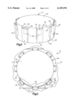
- FIG. 2 is a perspective view of a component of the air bag module of FIG. 1;
- FIG. 3 is a top view taken along line 3--3 in FIG. 1;
- FIG. 4 is an enlarged view of a portion of the air bag module of FIG. 1;
- FIG. 5 is an enlarged top view of a portion of an air bag module constructed in accordance with second embodiment of the present invention.
- FIG. 6 is a view similar to FIG. 5 illustrating a third embodiment of the present invention.
- FIG. 7 is a schematic view, partially in section, of a portion of an air bag module constructed in accordance with a fourth embodiment of the present invention.
- FIG. 8 is a view similar to FIG. 3 of an air bag module constructed in accordance with an fifth embodiment of the present invention.
- FIG. 9 is a view similar to FIG. 8 of an air bag module constructed in accordance with an sixth embodiment of the present invention.
- FIG. 1 illustrates a vehicle safety apparatus or air bag module 10.
- the air bag module 10 includes an inflatable vehicle occupant protection device or air bag 12 and an inflator 14.
- the inflator 14 is illustrated as a driver-side inflator and comprises a source of inflation fluid for inflating the air bag 12.
- the inflator 14 contains an ignitable gas generating material which, when ignited, rapidly produces a volume of gas to inflate the air bag 12.
- the inflator 14 could contain a stored quantity of pressurized inflation fluid, or could contain a combination of pressurized inflation fluid and ignitable material for heating the pressurized inflation fluid.
- the inflator 14 has a central axis 16 and includes a cylindrical enclosure member or housing 20.
- the housing 20 is preferably a stamped metal part having a cylindrical outer surface 22 extending parallel to the central axis 16 and a radially extending end surface 24 located at an upper (as viewed in FIG. 1) end of the inflator.
- a circumferentially spaced plurality of outlet openings 26 are formed in the housing 20 for directing inflation fluid out of the inflator 14 toward the air bag 12.
- the outlet openings 26 are identical in size and are spaced equally apart.
- the inflator 14 further includes a circumferentially spaced plurality of deflector flanges 30 formed in one piece with the stamped metal housing 20.
- the deflector flanges 30 project generally axially from a lower (as viewed in FIG. 1) end of the inflator 14 toward the upper end at which the end surface 24 is located.
- the deflector flanges 30 diverge, as they extend from the lower end of the inflator 14 toward the upper end of the inflator, at a slight angle a (FIG. 4) relative to the cylindrical outer surface 22 of the housing 20.
- Each of the deflector flanges 30 has a base panel 32 and first and second side panels 34 and 36, respectively (FIGS. 2 and 3).
- the first and second side panels 34 and 36 extend parallel to each other and perpendicular to the base panel 32.
- the side panels 34, 36 extend only partially along the length of the base panel 32 as best seen in FIG. 4.
- Each of the deflector flanges 30 is radially aligned with a respective one of the outlet openings 26.
- the base panel 32 of each deflector flange 30 completely overlies, but is spaced from, a respective one of the outlet openings 26.
- the first and second side panels 34 and 36 extend from the base panel 32 of each deflector flange 30 toward a respective portion of the outer surface 22 of the housing 20 surrounding each outlet opening 26.
- the side panels 34, 36 of the deflector flanges 30 do not contact the outer surface 22 of the housing 20. It is contemplated, however, that the side panels 34, 36 of the deflector flanges 30 could extend the entire length of the base panel 43 and project from the cylindrical outer surface 22 of the housing 20.
- a mounting flange 40 projects radially outward from a lower (as viewed in FIG. 1) end of the inflator 14.
- the mounting flange 40 has parallel upper and lower surfaces 42 and 44, respectively, and a circumferentially spaced plurality of fastener openings 46.
- a pair of lead wires 48 extend from the lower end of the inflator 14 and are electrically coupled with vehicle circuitry (not shown) for actuating the inflator, as known in the art.
- the upper surface 42 of the mounting flange 40 of the inflator 14 abuts a lower surface 52 of a mounting plate 50 attached to the vehicle steering wheel in a manner not shown.
- the mounting plate 50 has a central opening 54 for receiving the inflator 14.
- a circumferentially spaced plurality of fastener holes 56 are formed in the mounting plate 50. Each fastener hole 56 aligns with a respective one of the plurality of fastener openings 46 in the mounting flange 40 of the inflator 14.
- the air bag 12 (illustrated schematically by a single line in FIG. 1) is made from panels of a fabric material, such as woven nylon.
- the air bag 20 has inner and outer surfaces 60 and 62, respectively.
- a mouth portion 64 of the air bag 12 adjoins the mounting plate 50.
- the mouth portion 64 includes a central opening 66 through which the housing 20 of the inflator 14 extends.
- the outer surface 62 in the mouth portion 64 of the air bag 12 abuts an upper surface 68 of the mounting plate 50.
- a circumferentially spaced plurality of clearance holes 70 are located in the mouth portion 64 of the air bag 12.
- Each of the clearance holes 70 aligns with a respective one of the fastener openings 46 in the mounting flange 40 of the inflator 12 and with a respective one of the fastener holes 56 in the mounting plate 50.
- the air bag module includes a retaining ring 15 for retaining the air bag 12.
- the retaining ring 15 is generally circular in shape and circumscribes the inflator 14.
- the retaining ring 15 is made of metal and has a U-shaped cross-section.
- the retaining ring 15 overlies the mouth portion 64 of the air bag 12 and includes a circumferentially spaced plurality of fastener apertures 72.
- the fastener apertures 72 are located so as to align with the clearance holes 70 in the air bag 12, the fastener openings 46 in the mounting flange 40 of the inflator 14, and the fastener holes 56 in the mounting plate 50.
- a plurality of fasteners 80 extend axially through the aligned holes/openings 72, 70, 56 and 46 in the retaining ring 15, the air bag 12, the mounting plate 50, and the inflator mounting flange 40, respectively.
- the fasteners 80 clamp the mouth portion 64 of the air bag 12 between the retaining ring 15 and the mounting plate 50 to secure the air bag 12 in the air bag module 10.
- fasteners 80 could be any known type of fasteners such as bolts, studs, or screws.
- the air bag module 10 further includes a cover 90 which covers the folded air bag 12 and the inflator 14.
- the cover 90 is secured to the mounting plate 50 in a manner not shown.
- the cover 90 has a tear seam 92 at which the cover will tear to allow the air bag 12 to deploy after actuation of the inflator 14.
- the inflator 14 is actuated in a known manner to produce and release inflation fluid in the form of gas to inflate the air bag 12.
- the gas produced by the inflator may exit the inflator at a relatively high temperature.
- the gas may contain particulate matter resulting from the combustion of pyrotechnic materials inside the inflator 14. Such particulate matter carried by the gas may also exit the inflator 14 at a relatively high temperature.
- the gas produced by the actuated inflator 14 is directed out of the inflator through the outlet openings 26.
- the gas thus leaves the inflator 14 flowing in a radially outward direction through the outlet openings 26.
- the gas After the gas passes through the outlet openings 26, the gas impinges directly on the deflector flanges 30 located radially outward of the outlet openings.
- the inflation of the air bag 12 causes the tear seam 94 in the cover to rupture under the force of the expanding air bag so that the air bag can fully deploy into the passenger compartment of the vehicle.
- the configuration and location of the deflector flanges 30 over the outlet openings 26 prevents the inflation gas from impinging directly on the inner surface 60 of the air bag 12 as the gas exits the inflator 14.
- the flow of the gas into the deflector flanges 30 also reduces the velocity and temperature of the gas entering the air bag 12. Further, the flow of gas into the deflector flanges 30 provides an additional opportunity for particulate matter in the gas to precipitate out of the gas or plate out of the gas onto the deflector flanges prior to entry into the air bag.
- FIG. 5 illustrates a second embodiment of the present invention in which the first and second side panels 34a and 36a of each of the deflector flanges 30a extend at diverging angles from the base panel 32a. This configuration helps to distribute the inflation gas impinging upon the deflector flanges 30a across a central portion of the air bag 12.
- FIG. 6 illustrates a third embodiment of the present invention in which the first and second side panels 34b and 36b of each of the deflector flanges 30b extend at converging angles from the base panel 32b. This configuration helps to control the flow path of the inflation gas impinging upon the deflector flanges 30b to minimize the amount of gas flowing radially around the deflector flanges and into the air bag 12.
- FIG. 7 illustrates a fourth embodiment of the present invention in which the deflector flanges 30c are welded to the mounting flange 40 of the inflator 14, rather than being formed in one piece with the housing 20 as described above. Also, FIG. 7 illustrates a further modification of the deflector flanges 30c in that the deflector flanges extend axially parallel to the cylindrical outer surface 22 of the housing 20. It should be understood that the axially extending deflector flanges 30c do not have to be welded to the mounting flange 40, but could instead be formed in one piece with the housing 20 in the stamping process of the housing.
- FIG. 8 illustrates a fifth embodiment of the present invention in which a plurality of outlet openings 26d in the housing 20 and a corresponding plurality of deflector flanges 30d disposed radially outward of each outlet opening 26 are not equally spaced as with the first embodiment of FIGS. 1-4. Instead, in the fifth embodiment of FIG. 8, the outlet openings 26d and corresponding deflector flanges 30d are spaced unevenly about the circumference of the inflator 14. A majority of the outlet openings 26d and deflector flanges 30d are located on one half of the inflator 14 to direct a larger volume of the inflation fluid from the inflator into a given portion of the air bag 12.
- FIG. 9 illustrates a sixth embodiment of the present invention in which a plurality of outlet openings 26e and corresponding deflector flanges 30e are not identical in size as with the embodiment of FIGS. 1-4. Instead, in the embodiment of FIG. 9, a portion 26e' of the outlet openings 26e located on one half of the inflator have a larger diameter D1, while another portion of the outlet openings 26e have a smaller diameter D2.
- the deflector flanges 30e' associated with the larger diameter outlet openings 26e' have a correspondingly larger base panel 32e' with a circumferential length L1.
- the deflector flanges 30e associated with the smaller diameter outlet openings 26e have a correspondingly smaller base panel 32e with a circumferential length L2, as may be seen in FIG. 9.
- This configuration of the outlet openings 26e and deflector flanges 30e functions in a manner similar to the embodiment of FIG. 8 in that it directs a larger volume of the gas flow into a given portion of the air bag 12.
Abstract
Description
Claims (13)
Priority Applications (1)
| Application Number | Priority Date | Filing Date | Title |
|---|---|---|---|
| US09/132,341 US6149192A (en) | 1998-08-11 | 1998-08-11 | Inflator having gas deflector flanges |
Applications Claiming Priority (1)
| Application Number | Priority Date | Filing Date | Title |
|---|---|---|---|
| US09/132,341 US6149192A (en) | 1998-08-11 | 1998-08-11 | Inflator having gas deflector flanges |
Publications (1)
| Publication Number | Publication Date |
|---|---|
| US6149192A true US6149192A (en) | 2000-11-21 |
Family
ID=22453574
Family Applications (1)
| Application Number | Title | Priority Date | Filing Date |
|---|---|---|---|
| US09/132,341 Expired - Fee Related US6149192A (en) | 1998-08-11 | 1998-08-11 | Inflator having gas deflector flanges |
Country Status (1)
| Country | Link |
|---|---|
| US (1) | US6149192A (en) |
Cited By (29)
| Publication number | Priority date | Publication date | Assignee | Title |
|---|---|---|---|---|
| WO2002087930A1 (en) * | 2001-04-11 | 2002-11-07 | Autoliv Asp, Inc. | Vehicle occupant restraint module with disk inflator |
| US6568708B2 (en) * | 1999-12-22 | 2003-05-27 | Trw Occupant Restraint Systems Gmbh & Co. Kg | Gas bag module with gas guiding means |
| US20030141704A1 (en) * | 2001-11-27 | 2003-07-31 | Karl-Heinz Sommer | Airbag module with a deflector holder |
| US20040069178A1 (en) * | 2002-08-23 | 2004-04-15 | Mats Karlin | Inflator |
| US20040222621A1 (en) * | 2003-05-09 | 2004-11-11 | Thomas David E. | Air bag module diffuser |
| US6820892B2 (en) * | 2000-12-19 | 2004-11-23 | Nihon Plast Co., Ltd. | Air bag apparatus for vehicle |
| DE102004005555A1 (en) * | 2004-02-04 | 2005-09-08 | Autoliv Development Ab | Airbag module for a motor vehicle has an airbag with a generator for gas fed into the airbag to trigger the module, a diffuser and a deflector for protecting the airbag from gases flowing into it |
| US20060125212A1 (en) * | 2004-08-13 | 2006-06-15 | Takata-Petri Ag | Front-passenger airbag module |
| US20060138760A1 (en) * | 2004-12-28 | 2006-06-29 | Takata Corporation | Airbag with gas distribution pipe |
| US20060137300A1 (en) * | 2004-01-09 | 2006-06-29 | Van Scoyk Pershing R | Handgrip and stirrup support for bareback horse riding |
| US20060255578A1 (en) * | 2005-05-12 | 2006-11-16 | Choi Changsoo | Airbag inflation deflection module |
| US20070222194A1 (en) * | 2006-03-22 | 2007-09-27 | Trw Vehicle Safety Systems Inc. | Air bag module with a shield |
| US20070222196A1 (en) * | 2006-03-22 | 2007-09-27 | Trw Vehicle Safety Systems Inc. | Air bag module with an integral shield |
| US7438315B2 (en) * | 2004-05-28 | 2008-10-21 | Automotive Systems Laboratory, Inc. | Inflator and method of assembly |
| US20090033072A1 (en) * | 2007-06-22 | 2009-02-05 | Tk Holdings Inc. | Airbag assembly |
| US20090045607A1 (en) * | 2007-08-10 | 2009-02-19 | Toyoda Gosei., Ltd. | Airbag apparatus |
| JP2009062025A (en) * | 2007-08-10 | 2009-03-26 | Toyoda Gosei Co Ltd | Airbag apparatus |
| US20100181747A1 (en) * | 2009-01-22 | 2010-07-22 | Schorle Michael A | Airbag inflator manifold |
| US20100194078A1 (en) * | 2009-02-03 | 2010-08-05 | Trw Vehicle Safety Systems Inc. | Inflatable vehicle occupant protection device with inflation fluid deflector |
| US7938443B1 (en) * | 2010-08-20 | 2011-05-10 | Autoliv Asp, Inc. | Shipping-safe inflator for an airbag module |
| US20130069350A1 (en) * | 2011-09-21 | 2013-03-21 | Toyoda Gosei Co., Ltd. | Vibration damping structure for steering wheel |
| US20130257024A1 (en) * | 2012-03-29 | 2013-10-03 | Toyoda Gosei Co., Ltd. | Airbag apparatus |
| CN103534148A (en) * | 2011-05-02 | 2014-01-22 | Trw汽车股份有限公司 | Diffuser |
| US9180831B2 (en) * | 2013-11-29 | 2015-11-10 | Hyundai Mobis Co., Ltd. | Driver airbag apparatus |
| US9643563B2 (en) * | 2013-01-03 | 2017-05-09 | Key Safety Systems, Inc. | Airbag module with heat shield |
| WO2019208202A1 (en) * | 2018-04-26 | 2019-10-31 | Joyson Safety Systems Japan株式会社 | Air bag device |
| EP3583005A4 (en) * | 2017-02-16 | 2020-10-28 | ZF Passive Safety Systems US Inc. | Inflator filter |
| US11135994B2 (en) * | 2017-06-13 | 2021-10-05 | Arianegroup Sas | Pyrotechnical gas generator for an airbag |
| US11560113B2 (en) * | 2021-01-06 | 2023-01-24 | ZF Passive Safety Systems US Inc. | Airbag module with airbag retainer filter layer |
Citations (12)
| Publication number | Priority date | Publication date | Assignee | Title |
|---|---|---|---|---|
| US3602526A (en) * | 1968-11-12 | 1971-08-31 | Eaton Yale & Towne | Vehicle safety assembly having inflatable confinement |
| US4068862A (en) * | 1974-11-20 | 1978-01-17 | Nissan Motor Co., Ltd. | Safety bag inflation apparatus with extendible guard member against contact of bag with heated gas generator |
| US4178017A (en) * | 1974-11-20 | 1979-12-11 | Nissan Motor Company, Limited | Safety bag inflation apparatus with extendible guard member against contact of bag with heated gas generator |
| DE3604843A1 (en) * | 1986-02-15 | 1987-08-27 | Daimler Benz Ag | Gas generator |
| US4830401A (en) * | 1987-02-05 | 1989-05-16 | Honda Giken Kogyo Kabushiki Kaisha | Air bag assembly for restraining vehicle occupant |
| US4902036A (en) * | 1988-01-19 | 1990-02-20 | Talley Automotive Products, Inc. | Deflector ring for use with inflators with passive restraint devices |
| US5018762A (en) * | 1987-12-24 | 1991-05-28 | Nissan Motor Company, Ltd. | Air-bag device |
| US5246249A (en) * | 1990-05-30 | 1993-09-21 | Takata Corporation | Air bag unit |
| US5378011A (en) * | 1991-05-31 | 1995-01-03 | Alliedsignal Inc. | Air bag assembly |
| US5387007A (en) * | 1991-06-21 | 1995-02-07 | Dalcel Chemical Industries, Ltd. | Gas generator of thin-walled structure |
| US5836608A (en) * | 1996-12-11 | 1998-11-17 | Morton International, Inc. | Airbag deflection mount |
| US5918902A (en) * | 1996-04-12 | 1999-07-06 | Trw Occupant Restraint Systems Gmbh | Gas bag |
-
1998
- 1998-08-11 US US09/132,341 patent/US6149192A/en not_active Expired - Fee Related
Patent Citations (12)
| Publication number | Priority date | Publication date | Assignee | Title |
|---|---|---|---|---|
| US3602526A (en) * | 1968-11-12 | 1971-08-31 | Eaton Yale & Towne | Vehicle safety assembly having inflatable confinement |
| US4068862A (en) * | 1974-11-20 | 1978-01-17 | Nissan Motor Co., Ltd. | Safety bag inflation apparatus with extendible guard member against contact of bag with heated gas generator |
| US4178017A (en) * | 1974-11-20 | 1979-12-11 | Nissan Motor Company, Limited | Safety bag inflation apparatus with extendible guard member against contact of bag with heated gas generator |
| DE3604843A1 (en) * | 1986-02-15 | 1987-08-27 | Daimler Benz Ag | Gas generator |
| US4830401A (en) * | 1987-02-05 | 1989-05-16 | Honda Giken Kogyo Kabushiki Kaisha | Air bag assembly for restraining vehicle occupant |
| US5018762A (en) * | 1987-12-24 | 1991-05-28 | Nissan Motor Company, Ltd. | Air-bag device |
| US4902036A (en) * | 1988-01-19 | 1990-02-20 | Talley Automotive Products, Inc. | Deflector ring for use with inflators with passive restraint devices |
| US5246249A (en) * | 1990-05-30 | 1993-09-21 | Takata Corporation | Air bag unit |
| US5378011A (en) * | 1991-05-31 | 1995-01-03 | Alliedsignal Inc. | Air bag assembly |
| US5387007A (en) * | 1991-06-21 | 1995-02-07 | Dalcel Chemical Industries, Ltd. | Gas generator of thin-walled structure |
| US5918902A (en) * | 1996-04-12 | 1999-07-06 | Trw Occupant Restraint Systems Gmbh | Gas bag |
| US5836608A (en) * | 1996-12-11 | 1998-11-17 | Morton International, Inc. | Airbag deflection mount |
Cited By (47)
| Publication number | Priority date | Publication date | Assignee | Title |
|---|---|---|---|---|
| US6568708B2 (en) * | 1999-12-22 | 2003-05-27 | Trw Occupant Restraint Systems Gmbh & Co. Kg | Gas bag module with gas guiding means |
| US6820892B2 (en) * | 2000-12-19 | 2004-11-23 | Nihon Plast Co., Ltd. | Air bag apparatus for vehicle |
| US6702318B2 (en) * | 2001-04-11 | 2004-03-09 | Autoliv Asp, Inc. | Vehicle occupant restraint module with disk inflator |
| WO2002087930A1 (en) * | 2001-04-11 | 2002-11-07 | Autoliv Asp, Inc. | Vehicle occupant restraint module with disk inflator |
| US6854760B2 (en) * | 2001-04-11 | 2005-02-15 | Autoliv Asp, Inc. | Cylindrical passenger airbag module |
| US20030141704A1 (en) * | 2001-11-27 | 2003-07-31 | Karl-Heinz Sommer | Airbag module with a deflector holder |
| US7011336B2 (en) * | 2001-11-27 | 2006-03-14 | Autoliv Development Ab | Airbag module with a deflector holder |
| US7007610B2 (en) * | 2002-08-23 | 2006-03-07 | Autoliv Development Ab | Inflator |
| US20040069178A1 (en) * | 2002-08-23 | 2004-04-15 | Mats Karlin | Inflator |
| US6871872B2 (en) * | 2003-05-09 | 2005-03-29 | Key Safety Systems, Inc. | Air bag module diffuser |
| US20040222621A1 (en) * | 2003-05-09 | 2004-11-11 | Thomas David E. | Air bag module diffuser |
| US20060137300A1 (en) * | 2004-01-09 | 2006-06-29 | Van Scoyk Pershing R | Handgrip and stirrup support for bareback horse riding |
| DE102004005555A1 (en) * | 2004-02-04 | 2005-09-08 | Autoliv Development Ab | Airbag module for a motor vehicle has an airbag with a generator for gas fed into the airbag to trigger the module, a diffuser and a deflector for protecting the airbag from gases flowing into it |
| US7438315B2 (en) * | 2004-05-28 | 2008-10-21 | Automotive Systems Laboratory, Inc. | Inflator and method of assembly |
| US7431327B2 (en) * | 2004-08-13 | 2008-10-07 | Takata-Petri Ag | Front-passenger airbag module |
| US20060125212A1 (en) * | 2004-08-13 | 2006-06-15 | Takata-Petri Ag | Front-passenger airbag module |
| US20060138760A1 (en) * | 2004-12-28 | 2006-06-29 | Takata Corporation | Airbag with gas distribution pipe |
| US7497468B2 (en) * | 2005-05-12 | 2009-03-03 | Autoliv Asp, Inc. | Airbag inflation deflection module |
| US20060255578A1 (en) * | 2005-05-12 | 2006-11-16 | Choi Changsoo | Airbag inflation deflection module |
| US20070222194A1 (en) * | 2006-03-22 | 2007-09-27 | Trw Vehicle Safety Systems Inc. | Air bag module with a shield |
| US7618060B2 (en) | 2006-03-22 | 2009-11-17 | Trw Vehicle Safety Systems Inc. | Air bag module with an integral shield |
| US20070222196A1 (en) * | 2006-03-22 | 2007-09-27 | Trw Vehicle Safety Systems Inc. | Air bag module with an integral shield |
| US20090033072A1 (en) * | 2007-06-22 | 2009-02-05 | Tk Holdings Inc. | Airbag assembly |
| US8052167B2 (en) * | 2007-06-22 | 2011-11-08 | Tk Holdings Inc. | Airbag assembly |
| US7874575B2 (en) * | 2007-08-10 | 2011-01-25 | Toyoda Gosei Co., Ltd. | Airbag apparatus |
| US20090045607A1 (en) * | 2007-08-10 | 2009-02-19 | Toyoda Gosei., Ltd. | Airbag apparatus |
| JP2009062025A (en) * | 2007-08-10 | 2009-03-26 | Toyoda Gosei Co Ltd | Airbag apparatus |
| US8029017B2 (en) * | 2009-01-22 | 2011-10-04 | Toyoda Gosei Co. Ltd. | Airbag inflator manifold |
| US20100181747A1 (en) * | 2009-01-22 | 2010-07-22 | Schorle Michael A | Airbag inflator manifold |
| US7926837B2 (en) * | 2009-02-03 | 2011-04-19 | Trw Vehicle Safety Systems Inc. | Inflatable vehicle occupant protection device with inflation fluid deflector |
| US20100194078A1 (en) * | 2009-02-03 | 2010-08-05 | Trw Vehicle Safety Systems Inc. | Inflatable vehicle occupant protection device with inflation fluid deflector |
| US7938443B1 (en) * | 2010-08-20 | 2011-05-10 | Autoliv Asp, Inc. | Shipping-safe inflator for an airbag module |
| US20140062072A1 (en) * | 2011-05-02 | 2014-03-06 | Dominique Acker | Diffuser |
| CN103534148B (en) * | 2011-05-02 | 2016-11-09 | Trw汽车股份有限公司 | Bubbler |
| US9061652B2 (en) * | 2011-05-02 | 2015-06-23 | Trw Automotive Gmbh | Diffuser |
| CN103534148A (en) * | 2011-05-02 | 2014-01-22 | Trw汽车股份有限公司 | Diffuser |
| US20130069350A1 (en) * | 2011-09-21 | 2013-03-21 | Toyoda Gosei Co., Ltd. | Vibration damping structure for steering wheel |
| US8567818B2 (en) * | 2011-09-21 | 2013-10-29 | Toyoda Gosei Co., Ltd. | Vibration damping structure for steering wheel |
| US8827306B2 (en) * | 2012-03-29 | 2014-09-09 | Toyoda Gosei Co., Ltd. | Airbag apparatus |
| US20130257024A1 (en) * | 2012-03-29 | 2013-10-03 | Toyoda Gosei Co., Ltd. | Airbag apparatus |
| US9643563B2 (en) * | 2013-01-03 | 2017-05-09 | Key Safety Systems, Inc. | Airbag module with heat shield |
| US9180831B2 (en) * | 2013-11-29 | 2015-11-10 | Hyundai Mobis Co., Ltd. | Driver airbag apparatus |
| EP3583005A4 (en) * | 2017-02-16 | 2020-10-28 | ZF Passive Safety Systems US Inc. | Inflator filter |
| US11135994B2 (en) * | 2017-06-13 | 2021-10-05 | Arianegroup Sas | Pyrotechnical gas generator for an airbag |
| WO2019208202A1 (en) * | 2018-04-26 | 2019-10-31 | Joyson Safety Systems Japan株式会社 | Air bag device |
| JPWO2019208202A1 (en) * | 2018-04-26 | 2021-04-01 | Joyson Safety Systems Japan株式会社 | Airbag device |
| US11560113B2 (en) * | 2021-01-06 | 2023-01-24 | ZF Passive Safety Systems US Inc. | Airbag module with airbag retainer filter layer |
Similar Documents
| Publication | Publication Date | Title |
|---|---|---|
| US6149192A (en) | Inflator having gas deflector flanges | |
| US7618060B2 (en) | Air bag module with an integral shield | |
| US7152875B2 (en) | Air bag system | |
| US5062664A (en) | Air bag assembly | |
| EP1660355B1 (en) | Gas flow deflection apparatus and method for airbag systems | |
| US6702318B2 (en) | Vehicle occupant restraint module with disk inflator | |
| US5609356A (en) | Cylindrical air bag module assembly | |
| EP0471762A1 (en) | Air bag assembly. | |
| JPH08230596A (en) | Air bag arrester for fellow passenger | |
| US6089600A (en) | Integral gas direction device for an air bag | |
| US6250665B1 (en) | Retainer structure for an inflatable vehicle occupant protection device | |
| US6155599A (en) | Retaining ring with gas diffuser | |
| JP4444616B2 (en) | Expansion restraint module | |
| US6336659B1 (en) | Air bag module with inflator shield | |
| US5441299A (en) | Air bag inflator subassembly for installation onto the dashboard substrate of a motor vehicle | |
| US20080012277A1 (en) | Air bag module with a filter screen | |
| JP2002362274A (en) | Air bag and air bag device | |
| JPH10236256A (en) | Air bag device | |
| US20100194078A1 (en) | Inflatable vehicle occupant protection device with inflation fluid deflector | |
| US20070222194A1 (en) | Air bag module with a shield | |
| KR20010114138A (en) | Airbag | |
| US6176512B1 (en) | Apparatus for directing the flow of inflation fluid into an air bag | |
| US6164684A (en) | Fastening structure for interconnecting parts of a vehicle occupant protection apparatus | |
| US5826913A (en) | Air bag with retaining ring | |
| EP0698533B1 (en) | Apparatus for controlling flow of inflation fluid into an air bag |
Legal Events
| Date | Code | Title | Description |
|---|---|---|---|
| AS | Assignment |
Owner name: TRW INC., OHIO Free format text: ASSIGNMENT OF ASSIGNORS INTEREST;ASSIGNOR:SWANN, TIMOTHY A.;REEL/FRAME:009402/0024 Effective date: 19980806 Owner name: TRW VEHICLE SAFETY SYSTEMS INC., OHIO Free format text: ASSIGNMENT OF ASSIGNORS INTEREST;ASSIGNOR:BOWERS, PAUL A.;REEL/FRAME:009397/0372 Effective date: 19980804 |
|
| FEPP | Fee payment procedure |
Free format text: PAYOR NUMBER ASSIGNED (ORIGINAL EVENT CODE: ASPN); ENTITY STATUS OF PATENT OWNER: LARGE ENTITY |
|
| REMI | Maintenance fee reminder mailed | ||
| LAPS | Lapse for failure to pay maintenance fees | ||
| STCH | Information on status: patent discontinuation |
Free format text: PATENT EXPIRED DUE TO NONPAYMENT OF MAINTENANCE FEES UNDER 37 CFR 1.362 |
|
| FP | Lapsed due to failure to pay maintenance fee |
Effective date: 20041121 |