EP1215800A2 - Cooling passage in the slots of a rotating electric machine - Google Patents
Cooling passage in the slots of a rotating electric machine Download PDFInfo
- Publication number
- EP1215800A2 EP1215800A2 EP01125647A EP01125647A EP1215800A2 EP 1215800 A2 EP1215800 A2 EP 1215800A2 EP 01125647 A EP01125647 A EP 01125647A EP 01125647 A EP01125647 A EP 01125647A EP 1215800 A2 EP1215800 A2 EP 1215800A2
- Authority
- EP
- European Patent Office
- Prior art keywords
- slot
- stator
- electric machine
- rotating electric
- cooling passage
- Prior art date
- Legal status (The legal status is an assumption and is not a legal conclusion. Google has not performed a legal analysis and makes no representation as to the accuracy of the status listed.)
- Granted
Links
Images




Classifications
-
- H—ELECTRICITY
- H02—GENERATION; CONVERSION OR DISTRIBUTION OF ELECTRIC POWER
- H02K—DYNAMO-ELECTRIC MACHINES
- H02K3/00—Details of windings
- H02K3/04—Windings characterised by the conductor shape, form or construction, e.g. with bar conductors
- H02K3/24—Windings characterised by the conductor shape, form or construction, e.g. with bar conductors with channels or ducts for cooling medium between the conductors
-
- H—ELECTRICITY
- H02—GENERATION; CONVERSION OR DISTRIBUTION OF ELECTRIC POWER
- H02K—DYNAMO-ELECTRIC MACHINES
- H02K3/00—Details of windings
- H02K3/46—Fastening of windings on the stator or rotor structure
- H02K3/48—Fastening of windings on the stator or rotor structure in slots
- H02K3/487—Slot-closing devices
-
- H—ELECTRICITY
- H02—GENERATION; CONVERSION OR DISTRIBUTION OF ELECTRIC POWER
- H02K—DYNAMO-ELECTRIC MACHINES
- H02K9/00—Arrangements for cooling or ventilating
- H02K9/19—Arrangements for cooling or ventilating for machines with closed casing and closed-circuit cooling using a liquid cooling medium, e.g. oil
- H02K9/197—Arrangements for cooling or ventilating for machines with closed casing and closed-circuit cooling using a liquid cooling medium, e.g. oil in which the rotor or stator space is fluid-tight, e.g. to provide for different cooling media for rotor and stator
Definitions
- This invention relates to a rotating electric machine which is used as a motor, or as a generator, or as a motor/generator.
- Tokkai Sho 53 - 95207 published by the Japanese Patent Office in 1978 and Tokkai Hei 4 - 364343 published by the Japanese Patent Office in 1992 disclose a rotating electric machine which uses an inner section of a slot of a stator as a cooling passage in order to effectively cool the stator.
- the slot comprises a groove storing a stator coil.
- This type of rotating electric machine displays highly effective cooling performance since the stator coils or stator which generate heat come into direct contact with the cooling medium passing through the cooling passage.
- this invention provides a rotating electric machine having a stator with a slot housing coils, and a closing member for closing the opening of the slot and forming a cooling passage in the slot, the rotating electric machine comprising a regulating member for narrowing the cross-sectional area of the cooling passage in the slot.
- this invention provides a rotating electric machine, comprising a stator having a stator core and a slot, coils housed in the slot, a closing member for closing the opening of the slot and partitioning a cooling passage in the slot, wherein the coils are provided in a coiling region limited to a position near the bottom of the slot, and the overall region closer to the opening of the slot than the coils is filled by the closing member.
- Fig. 1 is a sectional view of a rotating electric machine applied to each embodiment of this invention.
- Fig. 2 is a partially sectional view showing a section of Fig. 1 along the line II - II of the stator before disposing a regulating member for regulating a cross sectional area of the passage according to a first embodiment of this invention.
- Fig. 3 is a partially sectional view showing a section of Fig. 1 along the line II - II of the stator according to a first embodiment of this invention.
- Fig. 4 is a partially sectional view showing a section of Fig. 1 along the line II - II of the stator according to a second embodiment of this invention.
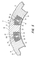
- Fig. 5 is a partially sectional view showing a section of Fig. 1 along the line II - II of the stator according to a third embodiment of this invention.
- Fig. 6 is a partially sectional view showing a section of Fig. 1 along the line II - II of the stator according to a fourth embodiment of this invention.
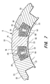
- Fig. 7 is a partially sectional view showing a section of Fig. 1 along the line II - II of the stator as partially manufactured, according to a fifth embodiment of this invention.
- Fig. 8 is a partially sectional view showing a section of Fig. 1 along the line II - II of the stator according to a fifth embodiment of this invention.
- the case 1 of the rotating electric machine comprises a cylindrical plate 1A and lateral plates 1B, 1C covering an opening on both axial ends of the cylindrical plate 1A.
- a columnar rotor 2 is housed in the case 1.
- the rotor 2 rotates about the rotation shaft 2A.
- Both ends of the rotation shaft 2A of the rotor 2 are supported on lateral plates 1B, 1C through respective bearings 3.
- a magnet 4 is provided in proximity to the outer peripheral face of the rotor 2.
- a cylindrical stator 5 is mounted on the inner peripheral face of the cylindrical plate 1A, encircling the rotor 2.
- a predetermined gap is provided between the inner peripheral face of the stator 5 and the outer peripheral face of the rotor 2. The width of the predetermined gap is less than 1.0 mm.
- the ring-shaped oil jackets 10, 11 with a U-shaped cross section are respectively mounted on both axial ends of the stator 5.
- Oil chambers 12, 13 are formed between the end face of the stator 5 and the inner side of the oil jackets 10, 11. Cooling oil is supplied to an oil chamber 12 through an oil supply mouth 16 which is formed in the oil jacket 10 and passes through the cylindrical plate 1A.
- the cooling oil is introduced into the oil chamber 13 through the cooling passage 29 formed in the stator 5 as shown in Fig. 2.
- the cooling oil introduced into the oil chamber 13 is discharged to the outside from an oil discharge mouth 17 which is formed in the oil jacket 11 and passes through the cylindrical plate 1A.
- a stator 5 will be described below in a state in which a regulating member is not fitted.
- the regulating member regulates the cross sectional area of a passage according to a first embodiment of this invention.
- the stator core 20 with a cylindrical shape is formed by connecting a plurality of divided cores 21. That is to say, the stator core 20 comprises divided cores. In this embodiment, the number of divided cores is twelve.
- Each of the divided cores 21 is formed by laminating a fixed number of T-shaped magnetic steel plates with respect to the rotation shaft 2A of the rotor 2. In other words, the plates are laminating perpendicular to the surface of the page in Fig. 2. Three of the twelve divided cores 21 included in the stator core 20 are shown in Fig. 2. The fixed number is determined by the thickness of the T-shaped magnetic steel plate and the required size of the stator core 20.
- An arrangement of divided cores according to the embodiments of this invention comprises back core sections of each divided core 21 being arranged in a cylindrical shape to form a back core section 22 of the stator core 20.
- the teeth of each divided core 21 comprise the teeth 23 of the stator core 20.
- An indentation between adjacent teeth 23, that is to say, a groove constitutes the slot 25.
- the length of the teeth 23, namely the degree of projection in a radial direction, the width, namely the thickness in a peripheral direction, and the interval between adjacent teeth 23, namely the size of the slot 25 are set to an optimal value in response to characteristics such as the output, torque and efficiency required by the rotating electric machine.
- the coils 30 are stored in the slot 25 by concentrated windings on each of the teeth 23.
- the windings of the coils 30 on the teeth 23 are performed in each divided core 21 before connecting them. That is to say, when manufacturing the stator 5, firstly wire is wound across a fixed layer on the teeth 23 of each of the divided cores 21 by a fixed number of windings, namely number of turns. Then the stator 5 is formed by arranging the divided cores 21 with coils wound thereon in the above manner.
- a predetermined number of divided cores 21 with the coils 30 are connected in a cylindrical shape to form the stator core 20, and the stator core 20 is fitted onto the inner peripheral face of the cylindrical plate 1A by shrink fitting for example.
- the predetermined number of divided cores in this embodiment is set at twelve.
- the stator 5 is provided with an arrangement of divided cores 21.
- Projections 26 project from both lateral faces on the tip of the teeth 23, namely from inner peripheral face of the opening of the slot 25.
- An under plate 40 is fitted onto an inner section of the projection 26.
- the under plate 40 is a closing member for closing the opening of the slot 25.
- the under plate 40 extends in a direction parallel to the rotation shaft 2A of the rotor 2 and closes the entire opening of the slot 25. In other words, the under plate 40 extends in a direction perpendicular to the surface of the page in Fig. 2.
- the space in the inner section of the slot 25 which is closed by the under plate 40 (apart from the space designated for the coils 30) comprises a cooling passage 29 extending in a direction parallel to the rotation shaft 2A.
- the cross-sectional area orthogonal to the rotation shaft 2A of the cooling passage 29 is termed a cross-sectional area S1.
- a regulating plate 41 for regulating the cross-sectional area of the passage is disposed as a regulating member in the cooling passage 29 formed as described above.
- the regulating plate 41 is disposed in substantially a central section of the slot 25 and extends in a direction parallel to the rotation shaft 2A of the rotor 2.
- an orientation with respect to the rotation shaft 2A of the rotor 2 corresponds to a direction which is perpendicular to the surface of the page.
- the regulating plate 41 is sandwiched and fixed between the bottom of the slot 25 and the inner face of the under plate 40.
- the bottom of the slot 25 means the back core section 22.
- the inner face of the under plate 40 is the surface which faces the inner side of the slot 25.
- a cross-sectional area S2 of a cooling passage 29A when a regulating plate 41 is provided corresponds to a cross-sectional area of the regulating plate 41 subtracted from the cross-sectional area S1 of the cooling passage 29. Therefore the respective cross-sectional areas display a relation of S1 greater than S2 (S1>S2).
- the regulating plate 41 is disposed in substantially a central section of the slot 25 and the cooling passage 29A is formed in a section in proximity to the coils 30.
- the cooling medium flows only in the narrow regions near to the coils 30 and unnecessary flow of cooling medium through sections apart from the coils 30 can be avoided. In other words, the amount of cooling medium required for cooling can be reduced.
- the degree of reduction in the cross-sectional area of the cooling passage 29A can be regulated by varying the cross-sectional area of the regulating plate 41. This allows corresponding streamlining of the design of the cooling structure in the rotating electric machine.
- stator 5 Referring to Fig. 4, the stator 5 according to a second embodiment of this invention will be described below.
- the under plate 42 closing the opening of the slot 25 comprises a main section 42A disposed along the opening of the slot 25 and a leg 42B extending towards a substantially central section inside the slot 25.
- the leg 42B regulates the cross-sectional area of the passage as a regulating member. That is to say, in this embodiment of the invention, the closing member and the regulating member are integrated.
- a cross-sectional area S3 of the cooling passage 29B is smaller than the cross-sectional area S1 of the cooling passage 29 in Fig. 2 by an area corresponding to the cross-sectional area of the leg 42B.
- stator 5 according to a third embodiment of this invention will be described below.
- the coils 30 are wound only in a coiling region limited to the bottom of the slot 25.
- This coiling region has a fixed range extending from the bottom of the slot 25 to the inner face of the under plate 43 along the length of the teeth 23.
- the coiling region is defined by the bottom of the slot 25, the inner face of the under plate 43, and the lateral faces of the teeth 23.
- the fixed range is determined, in the manner that the performance of the rotating electric machine and the cooling performance of the cooling passage is ensured.
- firstly five wire turns in a first layer there are firstly five wire turns in a first layer.
- the wire turns are performed from the base of the teeth 23 towards the tip without a clearance up to the end of the coiling region.
- a second layer comprising four wire turns, a third layer with five wire turns, a fourth layer with four wire turns and a fifth layer with two wire turns are wound over the first wire layer. In this manner, a total of twenty wire turns are performed on the teeth 23.
- the clearance between coils 30 wound on adjacent teeth 23 is smaller than in the first embodiment since there are five layers of coils 30 wound onto each of the teeth 23.
- the width of the coiling in the longitudinal direction of the teeth 23 narrows from a width corresponding to six turns as in the first embodiment to a width corresponding to five turns. As a result, a space is formed near to the opening of the slot 25 which is wider than that in the first embodiment above.
- An under plate 43 having a cross-sectional area which is larger than the under plate 40 in the first embodiment is fitted in order to fill the entire space near to the opening of the slot 25 which is wider in comparison to the first embodiment.
- the inner face of the under plate 43 comes into contact with the end of the coils 30 without a clearance.
- the cooling passage 29C is fixed in the slot 25 by the under plate 43.
- the cooling passage 29C comprises a section excluding the volume occupied by the coils 30 from the narrow coiling region in the slot 25. Since the cross-sectional area of the under plate 43 is greater than the cross-sectional area of the under plate 40, a cross-sectional area S4 of the cooling passage 29C is smaller than the cross-sectional area S1 of the cooling passage 29 in Fig. 2. Since this reduction in the cross-sectional area of the passage allows improvements in cooling efficiency, it is possible to effectively cool the stator 5 with a small amount of cooling medium.
- stator 5 Referring to Fig. 6, the stator 5 according to a fourth embodiment of this invention will be described below.
- the coils 30 are wound in a coiling region limited to the bottom of the slot 25 in the same manner as the stator 5 in the third embodiment as shown in Fig. 5.
- Stoppers 27 project from a face on both sides of the teeth 23 into the inner section of the slot. The stoppers 27 are positioned on the end of the coiling region near the opening of the slot 25.
- the coiling region is limited by the stopper 27. Windings are performed in a range from the base of the teeth 23 to the stopper 27. Furthermore the wound coils 30 are supported by the stopper 27 to prevent detachment from the coiling region to the opening of the slot 25. Since the region for winding coils 30 is limited to the coiling region on the bottom side of the slot 25, the number of layers of coils when winding with an equal number of turns can be increased in comparison to a case when the coiling region is not limited in the above manner. It is noted however that this arrangement also makes it possible to accurately regulate the windings with the function of the stopper.
- the under plate 44 closes the opening of the slot 25.
- the cross-sectional area S5 of the cooling passage 29D is smaller than cross-sectional area of the cooling passage 29 in Fig. 2.
- the section between the projection 26 and the stopper 27 comprises a retaining groove 28.
- the under plate 44 is gripped and fixed in the retaining groove 28 by an engagement section 44A on both ends of the under plate 44. In this manner, when the under plate 44 is fitted, accurate positioning is facilitated.
- FIG. 7 shows the stator 5 as partially manufactured.
- Fig. 8 shows the stator 5 as completed.
- a cross-sectional area S6 of the cooling passage 29E is decreased by winding coils 30 only in the coiling region on the bottom side of the slot 25 in the same manner as the third embodiment shown in Fig. 5 and the fourth embodiment shown in Fig. 6.
- the closing member partitioning the cooling passage 29E is characterized in being formed from two members, the two members being the resin-molded plate 45 (first member) and the under plate 46 (second member).
- a mold 51 is set along the inner peripheral face of the stator 5 and a plate-shaped mold 52 is set in each slot 25 of the stator 5 in order to form the resin-molded plate 45.
- the plate-shaped mold 52 has substantially the same shape as the under plate 46 and is set in order to make contact with the coils 30 stored in the slot 30.
- the cross-sectional area of a cooling passage 29E formed in the slot 25 may be reduced by fitting an under plate 46 with the result that the cooling performance is improved.
Landscapes
- Engineering & Computer Science (AREA)
- Power Engineering (AREA)
- Iron Core Of Rotating Electric Machines (AREA)
- Motor Or Generator Cooling System (AREA)
- Permanent Magnet Type Synchronous Machine (AREA)
- Windings For Motors And Generators (AREA)
Abstract
Description
Claims (8)
- A rotating electric machine having a stator (5) with a slot (25) housing coils, and a closing member (40, 42) for closing the opening of the slot (25) and forming a cooling passage (29A, 29B) in the slot (25), the rotating electric machine comprising:a regulating member (41, 42B) for narrowing the cross-sectional area of the cooling passage (29A, 29B) in the slot (25).
- The rotating electric machine as defined in Claim 1, wherein the closing member (42A) and the regulating member (42B) are integrated.
- The rotating electric machine as defined in Claim 2, wherein the regulating member (42B) extends from the main section (42A) of the closing member (42) into the slot.
- The rotating electric machine as defined in any one of Claim 1 to Claim 3, wherein the regulating member (41, 42B) is disposed in substantially a central section of the slot (25).
- A rotating electric machine, comprising:wherein the coils (30) are provided in a coiling region limited to a position near the bottom of the slot (25), and the overall region closer to the opening of the slot (25) than the coils (30) is filled by the closing member (43).a stator (5) having a stator core (20) and a slot (25);coils (30) housed in the slot (25);a closing member (43, 44, 45, 46) for closing the opening of the slot (25) and partitioning a cooling passage (29C, 29D, 29E) in the slot (25);
- The rotating electric machine as defined Claim 5, further comprising a stopper (27) projecting from the teeth (23) of the stator core (20) into the inner section of the slot (25) and being positioned on the end of the coiling region near the opening of the slot (25).
- The rotating electric machine as defined in Claim 5 or Claim 6, wherein the closing member (45, 46) comprises a first member (45) and a second member (46), the first member (45) molded of a resin in the slot opening, and the second member (46) buried after removing a mold member (52) used in the slot (25) to form the first member (45).
- The rotating electric machine as defined in any one of Claim 1 to Claim 7, wherein the stator (5) is formed by arranging a plurality of divided cores (21) with coils (30) in a cylindrical shape.
Applications Claiming Priority (2)
| Application Number | Priority Date | Filing Date | Title |
|---|---|---|---|
| JP2000379747A JP3603784B2 (en) | 2000-12-14 | 2000-12-14 | Rotating electric machine |
| JP2000379747 | 2000-12-14 |
Publications (3)
| Publication Number | Publication Date |
|---|---|
| EP1215800A2 true EP1215800A2 (en) | 2002-06-19 |
| EP1215800A3 EP1215800A3 (en) | 2003-04-09 |
| EP1215800B1 EP1215800B1 (en) | 2008-05-07 |
Family
ID=18848053
Family Applications (1)
| Application Number | Title | Priority Date | Filing Date |
|---|---|---|---|
| EP01125647A Expired - Lifetime EP1215800B1 (en) | 2000-12-14 | 2001-10-26 | Cooling passage in the slots of a rotating electric machine |
Country Status (4)
| Country | Link |
|---|---|
| US (1) | US6713927B2 (en) |
| EP (1) | EP1215800B1 (en) |
| JP (1) | JP3603784B2 (en) |
| DE (1) | DE60133872D1 (en) |
Cited By (14)
| Publication number | Priority date | Publication date | Assignee | Title |
|---|---|---|---|---|
| US6700283B2 (en) * | 2000-12-14 | 2004-03-02 | Nissan Motor Co., Ltd. | Rotating electric machine and method of manufacture therefor |
| US6809442B2 (en) * | 2001-09-26 | 2004-10-26 | Nissan Motor Co., Ltd. | Stator structure for rotary electric machine |
| US7126246B2 (en) | 2002-05-13 | 2006-10-24 | Honda Giken Kogyo Kabushiki Kaisha | Rotary electric machine with stator having an annular array of poles |
| GB2500040A (en) * | 2012-03-07 | 2013-09-11 | Nidec Sr Drives Ltd | Cooling of electrical machines |
| EP2757662A1 (en) * | 2013-01-17 | 2014-07-23 | Siemens Aktiengesellschaft | Stator tooth segmentation method for electric machines |
| WO2014012549A3 (en) * | 2012-07-16 | 2014-09-18 | Johnson Controls Denmark Aps | Canned electric machine and its use |
| WO2015188672A1 (en) * | 2014-06-13 | 2015-12-17 | 新疆金风科技股份有限公司 | Stator used for motor, motor and ventilation cooling method for motor |
| EP2568574A3 (en) * | 2011-09-09 | 2017-09-27 | Aisin Seiki Kabushiki Kaisha | Three-phase rotary electrical machine and manufacturing method thereof |
| WO2018167294A1 (en) * | 2017-03-17 | 2018-09-20 | Siemens Aktiengesellschaft | Stator having winding cooling for an electric machine |
| US10756599B2 (en) | 2017-09-26 | 2020-08-25 | Hyundai Motor Company | Oil circulation type motor and echo vehicle including the same |
| WO2021018706A1 (en) * | 2019-07-26 | 2021-02-04 | Thyssenkrupp Presta Ag | Stator and frame device for a stator of this kind |
| WO2021185493A1 (en) * | 2020-03-19 | 2021-09-23 | Siemens Gamesa Renewable Energy A/S | End of segment mechanical coil protection |
| FR3131477A1 (en) * | 2021-12-28 | 2023-06-30 | Thales | Electrical machine incorporating phase change materials. |
| US20230318402A1 (en) * | 2020-06-04 | 2023-10-05 | Vestas Wind Systems A/S | High voltage electric machine with improved stator insulation |
Families Citing this family (74)
| Publication number | Priority date | Publication date | Assignee | Title |
|---|---|---|---|---|
| US6933633B2 (en) * | 2001-10-03 | 2005-08-23 | Nissan Motor Co., Ltd. | Rotating electric machine and cooling structure for rotating electric machine |
| US20030177651A1 (en) * | 2002-03-25 | 2003-09-25 | Stone Steven D. | Bow sight |
| JPWO2004019468A1 (en) * | 2002-08-21 | 2005-12-15 | トヨタ自動車株式会社 | Vehicle motor |
| JP3882721B2 (en) * | 2002-09-13 | 2007-02-21 | 日産自動車株式会社 | Cooling structure for rotating electrical machine and method for manufacturing the same |
| WO2004084219A1 (en) * | 2003-03-17 | 2004-09-30 | Sae Magnetics (H.K) Ltd. | System and method for manufacturing a hard disk drive suspension flexure and for preventing damage due to electrical arcing |
| US7119467B2 (en) | 2003-03-21 | 2006-10-10 | Pratt & Whitney Canada Corp. | Current limiting means for a generator |
| US6920023B2 (en) * | 2003-03-21 | 2005-07-19 | Pratt & Whitney Canada Corp. | Current limiting means for a generator |
| US6844653B2 (en) * | 2003-03-31 | 2005-01-18 | Valeo Electrical Systems, Inc. | Stator design for permanent magnet motor with combination slot wedge and tooth locator |
| FR2857521B1 (en) * | 2003-07-11 | 2005-09-23 | Thales Sa | COOLER OF A STATOR |
| JP4135647B2 (en) * | 2004-01-29 | 2008-08-20 | 日産自動車株式会社 | Stator structure of multi-axis multilayer motor |
| US7525223B2 (en) * | 2004-04-14 | 2009-04-28 | Yue Chung Chen | Induction motor having the rotor located within a shell |
| CN100559683C (en) * | 2004-12-06 | 2009-11-11 | 日产自动车株式会社 | Motor/generator |
| US7226277B2 (en) * | 2004-12-22 | 2007-06-05 | Pratt & Whitney Canada Corp. | Pump and method |
| JP4687180B2 (en) * | 2005-03-25 | 2011-05-25 | 日産自動車株式会社 | Motor generator cooling structure |
| DE102005051245A1 (en) * | 2005-10-26 | 2007-05-10 | Festool Gmbh | Electric motor and method for its production |
| US7538457B2 (en) * | 2006-01-27 | 2009-05-26 | General Motors Corporation | Electric motor assemblies with coolant flow for concentrated windings |
| US20070200437A1 (en) * | 2006-02-27 | 2007-08-30 | El-Antably Ahmed M | Stator assembly and manufacturing method |
| US7479716B2 (en) | 2006-02-27 | 2009-01-20 | General Motors Corporation | Cooling system for a stator assembly |
| US8129880B2 (en) * | 2007-11-15 | 2012-03-06 | GM Global Technology Operations LLC | Concentrated winding machine with magnetic slot wedges |
| DE102007062540A1 (en) * | 2007-12-20 | 2009-06-25 | Sycotec Gmbh & Co. Kg | Electric motor or generator |
| JP5281822B2 (en) * | 2008-05-21 | 2013-09-04 | 山洋電気株式会社 | Stator for rotating electrical machine |
| JP4670942B2 (en) * | 2008-11-21 | 2011-04-13 | トヨタ自動車株式会社 | Rotating electric machine |
| JP2010124657A (en) * | 2008-11-21 | 2010-06-03 | Toyota Motor Corp | Rotating electric machine |
| JP5330860B2 (en) * | 2009-02-27 | 2013-10-30 | トヨタ自動車株式会社 | Rotating electric machine |
| CN102422512A (en) * | 2009-03-05 | 2012-04-18 | Cpm小型电动马达有限公司 | double rotor motor |
| JP5297364B2 (en) * | 2009-12-17 | 2013-09-25 | アイチエレック株式会社 | Electric motor |
| US8373316B2 (en) * | 2011-01-12 | 2013-02-12 | Kollmorgen Corporation | Coolant flow enhancing device for stator coil end turns of fluid cooled electric motor |
| US8558422B2 (en) | 2011-03-31 | 2013-10-15 | Caterpillar Inc. | Uniform contained cooling for stator |
| JP5331160B2 (en) * | 2011-05-18 | 2013-10-30 | トヨタ自動車株式会社 | Coil fixing member of rotating electric machine and rotating electric machine |
| CN102263446A (en) * | 2011-08-23 | 2011-11-30 | 浙江泰达微电机有限公司 | Stator punching sheet beneficial to heat radiation |
| DE102011121793B4 (en) * | 2011-12-21 | 2017-05-24 | Sew-Eurodrive Gmbh & Co Kg | electric motor |
| JP5714548B2 (en) * | 2011-12-22 | 2015-05-07 | ヤマハ発動機株式会社 | Rotating electrical machine |
| CN103187842B (en) * | 2011-12-28 | 2015-07-01 | 日本电产株式会社 | Single-phase induction motor |
| EP2674256B1 (en) * | 2012-06-15 | 2021-11-10 | Black & Decker Inc. | Brushless motor commutation control in a power tool |
| JP6000701B2 (en) * | 2012-07-10 | 2016-10-05 | 日立建機株式会社 | Generator motor and electric vehicle using the same |
| DE102012217711A1 (en) * | 2012-09-28 | 2014-04-03 | Magna Powertrain Ag & Co. Kg | Electric machine with cooling |
| KR101378885B1 (en) * | 2012-10-04 | 2014-03-31 | 엘지전자 주식회사 | Electric motor |
| JP5725003B2 (en) * | 2012-12-26 | 2015-05-27 | トヨタ自動車株式会社 | Rotating electric machine |
| JP5909203B2 (en) * | 2013-02-25 | 2016-04-26 | 信越化学工業株式会社 | Reactor for producing polycrystalline silicon and method for producing polycrystalline silicon |
| US9506473B2 (en) * | 2013-03-04 | 2016-11-29 | Asia Vital Components | Protection structure and a fan thereof |
| US9523368B2 (en) * | 2013-03-04 | 2016-12-20 | Asia Vital Components Co., Ltd. | Stator module with protection structure and a fan thereof |
| US9252637B2 (en) * | 2013-04-25 | 2016-02-02 | GM Global Technology Operations LLC | Coil retainer for electric machine rotors |
| JP6140566B2 (en) * | 2013-07-31 | 2017-05-31 | アイシン・エィ・ダブリュ株式会社 | Coil mounting method and coil mounting jig |
| DE102013219535A1 (en) * | 2013-09-27 | 2015-04-02 | Mahle International Gmbh | Stator arrangement for an electric motor |
| DE102014207468A1 (en) * | 2014-04-17 | 2015-10-22 | Zf Friedrichshafen Ag | Cooling for a winding head of an electric machine |
| AU2015292779B2 (en) | 2014-07-21 | 2020-07-09 | Prime Datum Development Company, Llc | Cooling schemes and methods for cooling tower motors |
| JP6442250B2 (en) * | 2014-11-25 | 2018-12-19 | 株式会社ニッキ | Brushless motor integrated pump |
| US11190062B2 (en) * | 2015-03-04 | 2021-11-30 | Hitachi Industrial Equipment Systems Co., Ltd. | Axial gap type rotating electric machine and stator |
| CN108702042B (en) * | 2016-02-25 | 2020-10-23 | 株式会社安川电机 | Rotating electrical machine and method for manufacturing rotating electrical machine |
| DE102017118792A1 (en) * | 2017-08-17 | 2019-02-21 | Wobben Properties Gmbh | Wind turbine generator as well as slot wedge for it and wind turbine with it |
| EP3780355A4 (en) * | 2018-04-09 | 2021-06-09 | Mitsubishi Electric Corporation | Rotating electric machine and electric power steering device having rotating electric machine |
| DE102018213558A1 (en) * | 2018-08-10 | 2020-02-13 | Bayerische Motoren Werke Aktiengesellschaft | Electric machine for a motor vehicle and stator for an electric machine |
| US11002289B2 (en) * | 2018-08-28 | 2021-05-11 | Caterpillar Inc. | Cooling system for a rotary electric machine |
| DE102019111336A1 (en) * | 2019-05-02 | 2020-11-05 | Festool Gmbh | Drive motor with a slot cover |
| US11581775B2 (en) | 2019-05-14 | 2023-02-14 | Hanon Systems | Device for driving a compressor with an insulation arrangement |
| DE102019112534A1 (en) * | 2019-05-14 | 2020-11-19 | Hanon Systems | Device for driving a compressor with an insulation arrangement |
| DE102019210028A1 (en) * | 2019-07-08 | 2021-01-14 | Brose Fahrzeugteile SE & Co. Kommanditgesellschaft, Würzburg | Electric motor and cooling fan |
| GB2587187B (en) * | 2019-09-11 | 2022-07-27 | Rolls Royce Plc | Electric Machines |
| GB2587186A (en) * | 2019-09-11 | 2021-03-24 | Rolls Royce Plc | Electric Machines |
| DE102020131884A1 (en) * | 2019-12-03 | 2021-06-10 | Borgwarner Inc. | Thermally conductive groove partition |
| DE102020200323A1 (en) | 2020-01-13 | 2021-07-15 | Robert Bosch Gesellschaft mit beschränkter Haftung | Stator of an electrical machine |
| EP3934059A1 (en) * | 2020-06-30 | 2022-01-05 | Siemens Gamesa Renewable Energy A/S | Electrical machine having a segmented stator or rotor |
| DE102020117267B4 (en) | 2020-07-01 | 2022-01-20 | Dr. Ing. H.C. F. Porsche Aktiengesellschaft | Stator arrangement with cooling |
| US11764629B2 (en) * | 2020-12-23 | 2023-09-19 | Delta Electronics, Inc. | In-slot cooling system for an electric machine with hairpin windings |
| WO2022157839A1 (en) * | 2021-01-20 | 2022-07-28 | 三菱電機株式会社 | Rotary electrical device and cooling system for rotary electrical device |
| DE102021201793A1 (en) | 2021-02-25 | 2022-08-25 | Rolls-Royce Deutschland Ltd & Co Kg | Segmented coil carrier with slot wedges |
| DE102021205864A1 (en) | 2021-06-10 | 2022-12-15 | Robert Bosch Gesellschaft mit beschränkter Haftung | Stator of an electrical machine |
| JP7740082B2 (en) * | 2022-03-22 | 2025-09-17 | 株式会社豊田自動織機 | electric motor |
| DE102023110854A1 (en) * | 2022-06-14 | 2023-12-14 | Hanon Systems | Insulation system for a stator of an electric motor |
| FR3138586B1 (en) * | 2022-07-28 | 2024-07-26 | Valeo Equip Electr Moteur | Stator for a rotating electrical machine |
| DE102023207733A1 (en) | 2023-08-11 | 2025-02-13 | Robert Bosch Gesellschaft mit beschränkter Haftung | Slot closure for a stator, stator and an electrical machine |
| US20250323543A1 (en) * | 2024-04-12 | 2025-10-16 | Caterpillar Inc. | Stator assembly |
| SE548062C2 (en) * | 2024-05-15 | 2026-02-17 | Traton Ab | Slot Sealing Element and Electric Machine and Vehicle |
| DE102024206725A1 (en) * | 2024-07-17 | 2026-01-22 | Volkswagen Aktiengesellschaft | Rotor with cover slide, electric motor and motor vehicle |
Family Cites Families (13)
| Publication number | Priority date | Publication date | Assignee | Title |
|---|---|---|---|---|
| US2899573A (en) * | 1959-08-11 | Cqoling arrangement for salient pole rotors | ||
| JPS5395207A (en) | 1977-02-01 | 1978-08-21 | Toshiba Corp | Electric rotary machine |
| US4227108A (en) * | 1978-04-24 | 1980-10-07 | Tokyo Shibaura Electric Co., Ltd. | Glass compound layer for mechanical and thermal protection of a laminated iron core rotary electromachine |
| JPS5829345A (en) * | 1981-08-14 | 1983-02-21 | Toshiba Corp | Salient-pole type rotary electric machine |
| US4409502A (en) * | 1981-12-17 | 1983-10-11 | Westinghouse Electric Corp. | Self-cooled electrical machine with integrated fan and salient pole rotor |
| JPS5941114A (en) | 1982-08-30 | 1984-03-07 | 三菱電機株式会社 | Digital protecting relay unit |
| JPS5941147A (en) * | 1982-08-30 | 1984-03-07 | Mitsubishi Electric Corp | Rotor for rotary electric machine |
| JP2716286B2 (en) | 1991-06-10 | 1998-02-18 | ファナック株式会社 | Cooling structure of stator winding in motor and method of manufacturing the same |
| JP3355700B2 (en) * | 1993-06-14 | 2002-12-09 | 松下電器産業株式会社 | Rotating electric machine stator |
| US5519269A (en) * | 1994-06-10 | 1996-05-21 | Westinghouse Electric Corp. | Electric induction motor and related method of cooling |
| TW380329B (en) * | 1997-04-16 | 2000-01-21 | Japan Servo | Permanent-magnet revolving electrodynamic machine with a concentrated winding stator |
| JP3440782B2 (en) * | 1997-10-29 | 2003-08-25 | 三菱電機株式会社 | Reluctance motor and reluctance motor for driving compressor |
| US6113024A (en) * | 1999-04-30 | 2000-09-05 | Alliedsignal Inc. | Winding wedge retention to maintain coil form |
-
2000
- 2000-12-14 JP JP2000379747A patent/JP3603784B2/en not_active Expired - Fee Related
-
2001
- 2001-10-26 EP EP01125647A patent/EP1215800B1/en not_active Expired - Lifetime
- 2001-10-26 DE DE60133872T patent/DE60133872D1/en not_active Expired - Lifetime
- 2001-11-07 US US09/986,046 patent/US6713927B2/en not_active Expired - Fee Related
Cited By (20)
| Publication number | Priority date | Publication date | Assignee | Title |
|---|---|---|---|---|
| US6700283B2 (en) * | 2000-12-14 | 2004-03-02 | Nissan Motor Co., Ltd. | Rotating electric machine and method of manufacture therefor |
| US6809442B2 (en) * | 2001-09-26 | 2004-10-26 | Nissan Motor Co., Ltd. | Stator structure for rotary electric machine |
| US7126246B2 (en) | 2002-05-13 | 2006-10-24 | Honda Giken Kogyo Kabushiki Kaisha | Rotary electric machine with stator having an annular array of poles |
| EP2568574A3 (en) * | 2011-09-09 | 2017-09-27 | Aisin Seiki Kabushiki Kaisha | Three-phase rotary electrical machine and manufacturing method thereof |
| GB2500040A (en) * | 2012-03-07 | 2013-09-11 | Nidec Sr Drives Ltd | Cooling of electrical machines |
| GB2500040B (en) * | 2012-03-07 | 2018-07-04 | Nidec Sr Drives Ltd | Cooling of electrical machines |
| WO2014012549A3 (en) * | 2012-07-16 | 2014-09-18 | Johnson Controls Denmark Aps | Canned electric machine and its use |
| EP2757662A1 (en) * | 2013-01-17 | 2014-07-23 | Siemens Aktiengesellschaft | Stator tooth segmentation method for electric machines |
| WO2014111220A1 (en) * | 2013-01-17 | 2014-07-24 | Siemens Aktiengesellschaft | Stator tooth segmentation method for electric machines |
| US10644557B2 (en) | 2014-06-13 | 2020-05-05 | Xinjiang Goldwind Science & Technology Co., Ltd. | Stator used for motor, motor and ventilation cooling method for motor |
| WO2015188672A1 (en) * | 2014-06-13 | 2015-12-17 | 新疆金风科技股份有限公司 | Stator used for motor, motor and ventilation cooling method for motor |
| WO2018167294A1 (en) * | 2017-03-17 | 2018-09-20 | Siemens Aktiengesellschaft | Stator having winding cooling for an electric machine |
| US11539256B2 (en) | 2017-03-17 | 2022-12-27 | Siemens Aktiengesellschaft | Stator having winding cooling for an electrical machine |
| US10756599B2 (en) | 2017-09-26 | 2020-08-25 | Hyundai Motor Company | Oil circulation type motor and echo vehicle including the same |
| EP3460958B1 (en) * | 2017-09-26 | 2023-11-15 | Hyundai Motor Company | Oil circulation type motor and eco vehicle including the same |
| WO2021018706A1 (en) * | 2019-07-26 | 2021-02-04 | Thyssenkrupp Presta Ag | Stator and frame device for a stator of this kind |
| WO2021185493A1 (en) * | 2020-03-19 | 2021-09-23 | Siemens Gamesa Renewable Energy A/S | End of segment mechanical coil protection |
| US20230318402A1 (en) * | 2020-06-04 | 2023-10-05 | Vestas Wind Systems A/S | High voltage electric machine with improved stator insulation |
| US12470110B2 (en) * | 2020-06-04 | 2025-11-11 | Vestas Wind Systems A/S | High voltage electric machine with improved stator insulation |
| FR3131477A1 (en) * | 2021-12-28 | 2023-06-30 | Thales | Electrical machine incorporating phase change materials. |
Also Published As
| Publication number | Publication date |
|---|---|
| DE60133872D1 (en) | 2008-06-19 |
| EP1215800B1 (en) | 2008-05-07 |
| US6713927B2 (en) | 2004-03-30 |
| JP2002186205A (en) | 2002-06-28 |
| JP3603784B2 (en) | 2004-12-22 |
| US20020074871A1 (en) | 2002-06-20 |
| EP1215800A3 (en) | 2003-04-09 |
Similar Documents
| Publication | Publication Date | Title |
|---|---|---|
| US6713927B2 (en) | Rotating electric machine | |
| EP1215801B1 (en) | Rotating electric machine and method of manufacture therefor | |
| US6495936B2 (en) | Rotating electrical machine | |
| US6933633B2 (en) | Rotating electric machine and cooling structure for rotating electric machine | |
| AU674784B2 (en) | Electric rotating machine | |
| US5864193A (en) | Electric rotating machine having improved insulation for an armature coil | |
| US7508109B2 (en) | Commutator motor | |
| US20220385127A1 (en) | Stator of an electric machine, method for producing same and electric machine | |
| JP5533285B2 (en) | Insulating member and stator manufacturing method | |
| US20050012427A1 (en) | Claw pole motor stator | |
| JP2004248429A (en) | Stator coil module, method of manufacturing the same, and rotating electric machine | |
| KR100833734B1 (en) | Fuel pump, motor device for the same, and method for manufacturing the same | |
| JP2003009454A (en) | Rotating electric machine | |
| US6798091B2 (en) | Watertight brushless fan motor | |
| US5650683A (en) | Electric rotating machine | |
| CN1972077A (en) | Split stator of electric motor | |
| JP6815872B2 (en) | Motors and motor manufacturing methods | |
| JP2004112856A (en) | Cooling structure of rotating electric machine and method of manufacturing the same | |
| EP3846320A1 (en) | Motor | |
| JP2002136034A (en) | Dc brushless motor | |
| CN101044666B (en) | Method for sheathing an armature for electric machines | |
| JP2004336998A (en) | Rotating electric machine and method for manufacturing rotating electric machine | |
| KR20230020496A (en) | Cooling structure of rotary electric machine and rotary electric machine | |
| US20200161913A1 (en) | Rotor and motor | |
| KR20220144322A (en) | Electric motor vehicle traction motor |
Legal Events
| Date | Code | Title | Description |
|---|---|---|---|
| PUAI | Public reference made under article 153(3) epc to a published international application that has entered the european phase |
Free format text: ORIGINAL CODE: 0009012 |
|
| 17P | Request for examination filed |
Effective date: 20011026 |
|
| AK | Designated contracting states |
Kind code of ref document: A2 Designated state(s): AT BE CH CY DE DK ES FI FR GB GR IE IT LI LU MC NL PT SE TR |
|
| AX | Request for extension of the european patent |
Free format text: AL;LT;LV;MK;RO;SI |
|
| PUAL | Search report despatched |
Free format text: ORIGINAL CODE: 0009013 |
|
| AK | Designated contracting states |
Kind code of ref document: A3 Designated state(s): AT BE CH CY DE DK ES FI FR GB GR IE IT LI LU MC NL PT SE TR |
|
| AX | Request for extension of the european patent |
Extension state: AL LT LV MK RO SI |
|
| AKX | Designation fees paid |
Designated state(s): DE FR GB |
|
| 17Q | First examination report despatched |
Effective date: 20070301 |
|
| GRAP | Despatch of communication of intention to grant a patent |
Free format text: ORIGINAL CODE: EPIDOSNIGR1 |
|
| GRAS | Grant fee paid |
Free format text: ORIGINAL CODE: EPIDOSNIGR3 |
|
| GRAA | (expected) grant |
Free format text: ORIGINAL CODE: 0009210 |
|
| AK | Designated contracting states |
Kind code of ref document: B1 Designated state(s): DE FR GB |
|
| REG | Reference to a national code |
Ref country code: GB Ref legal event code: FG4D |
|
| REF | Corresponds to: |
Ref document number: 60133872 Country of ref document: DE Date of ref document: 20080619 Kind code of ref document: P |
|
| PLBE | No opposition filed within time limit |
Free format text: ORIGINAL CODE: 0009261 |
|
| STAA | Information on the status of an ep patent application or granted ep patent |
Free format text: STATUS: NO OPPOSITION FILED WITHIN TIME LIMIT |
|
| 26N | No opposition filed |
Effective date: 20090210 |
|
| PGFP | Annual fee paid to national office [announced via postgrant information from national office to epo] |
Ref country code: GB Payment date: 20141022 Year of fee payment: 14 Ref country code: DE Payment date: 20141023 Year of fee payment: 14 Ref country code: FR Payment date: 20141008 Year of fee payment: 14 |
|
| REG | Reference to a national code |
Ref country code: DE Ref legal event code: R119 Ref document number: 60133872 Country of ref document: DE |
|
| GBPC | Gb: european patent ceased through non-payment of renewal fee |
Effective date: 20151026 |
|
| PG25 | Lapsed in a contracting state [announced via postgrant information from national office to epo] |
Ref country code: GB Free format text: LAPSE BECAUSE OF NON-PAYMENT OF DUE FEES Effective date: 20151026 Ref country code: DE Free format text: LAPSE BECAUSE OF NON-PAYMENT OF DUE FEES Effective date: 20160503 |
|
| REG | Reference to a national code |
Ref country code: FR Ref legal event code: ST Effective date: 20160630 |
|
| PG25 | Lapsed in a contracting state [announced via postgrant information from national office to epo] |
Ref country code: FR Free format text: LAPSE BECAUSE OF NON-PAYMENT OF DUE FEES Effective date: 20151102 |