EP2674256B1 - Brushless motor commutation control in a power tool - Google Patents
Brushless motor commutation control in a power tool Download PDFInfo
- Publication number
- EP2674256B1 EP2674256B1 EP13172319.9A EP13172319A EP2674256B1 EP 2674256 B1 EP2674256 B1 EP 2674256B1 EP 13172319 A EP13172319 A EP 13172319A EP 2674256 B1 EP2674256 B1 EP 2674256B1
- Authority
- EP
- European Patent Office
- Prior art keywords
- low
- motor
- phase
- power
- control unit
- Prior art date
- Legal status (The legal status is an assumption and is not a legal conclusion. Google has not performed a legal analysis and makes no representation as to the accuracy of the status listed.)
- Active
Links
- 238000004804 winding Methods 0.000 claims description 12
- 238000010586 diagram Methods 0.000 description 12
- 238000000034 method Methods 0.000 description 7
- 230000007246 mechanism Effects 0.000 description 5
- 230000001360 synchronised effect Effects 0.000 description 3
- 230000005540 biological transmission Effects 0.000 description 2
- 230000006872 improvement Effects 0.000 description 2
- 230000005355 Hall effect Effects 0.000 description 1
- 238000010276 construction Methods 0.000 description 1
- 230000005611 electricity Effects 0.000 description 1
- 230000005669 field effect Effects 0.000 description 1
- 230000020169 heat generation Effects 0.000 description 1
- 230000004048 modification Effects 0.000 description 1
- 238000012986 modification Methods 0.000 description 1
- 238000012544 monitoring process Methods 0.000 description 1
- 230000009467 reduction Effects 0.000 description 1
Images


Classifications
-
- H—ELECTRICITY
- H02—GENERATION; CONVERSION OR DISTRIBUTION OF ELECTRIC POWER
- H02K—DYNAMO-ELECTRIC MACHINES
- H02K3/00—Details of windings
- H02K3/32—Windings characterised by the shape, form or construction of the insulation
- H02K3/34—Windings characterised by the shape, form or construction of the insulation between conductors or between conductor and core, e.g. slot insulation
-
- H—ELECTRICITY
- H02—GENERATION; CONVERSION OR DISTRIBUTION OF ELECTRIC POWER
- H02P—CONTROL OR REGULATION OF ELECTRIC MOTORS, ELECTRIC GENERATORS OR DYNAMO-ELECTRIC CONVERTERS; CONTROLLING TRANSFORMERS, REACTORS OR CHOKE COILS
- H02P27/00—Arrangements or methods for the control of AC motors characterised by the kind of supply voltage
- H02P27/04—Arrangements or methods for the control of AC motors characterised by the kind of supply voltage using variable-frequency supply voltage, e.g. inverter or converter supply voltage
- H02P27/06—Arrangements or methods for the control of AC motors characterised by the kind of supply voltage using variable-frequency supply voltage, e.g. inverter or converter supply voltage using dc to ac converters or inverters
- H02P27/08—Arrangements or methods for the control of AC motors characterised by the kind of supply voltage using variable-frequency supply voltage, e.g. inverter or converter supply voltage using dc to ac converters or inverters with pulse width modulation
-
- B—PERFORMING OPERATIONS; TRANSPORTING
- B25—HAND TOOLS; PORTABLE POWER-DRIVEN TOOLS; MANIPULATORS
- B25F—COMBINATION OR MULTI-PURPOSE TOOLS NOT OTHERWISE PROVIDED FOR; DETAILS OR COMPONENTS OF PORTABLE POWER-DRIVEN TOOLS NOT PARTICULARLY RELATED TO THE OPERATIONS PERFORMED AND NOT OTHERWISE PROVIDED FOR
- B25F5/00—Details or components of portable power-driven tools not particularly related to the operations performed and not otherwise provided for
-
- H—ELECTRICITY
- H02—GENERATION; CONVERSION OR DISTRIBUTION OF ELECTRIC POWER
- H02K—DYNAMO-ELECTRIC MACHINES
- H02K7/00—Arrangements for handling mechanical energy structurally associated with dynamo-electric machines, e.g. structural association with mechanical driving motors or auxiliary dynamo-electric machines
- H02K7/14—Structural association with mechanical loads, e.g. with hand-held machine tools or fans
- H02K7/145—Hand-held machine tool
-
- H—ELECTRICITY
- H02—GENERATION; CONVERSION OR DISTRIBUTION OF ELECTRIC POWER
- H02P—CONTROL OR REGULATION OF ELECTRIC MOTORS, ELECTRIC GENERATORS OR DYNAMO-ELECTRIC CONVERTERS; CONTROLLING TRANSFORMERS, REACTORS OR CHOKE COILS
- H02P29/00—Arrangements for regulating or controlling electric motors, appropriate for both AC and DC motors
- H02P29/60—Controlling or determining the temperature of the motor or of the drive
- H02P29/68—Controlling or determining the temperature of the motor or of the drive based on the temperature of a drive component or a semiconductor component
-
- H—ELECTRICITY
- H02—GENERATION; CONVERSION OR DISTRIBUTION OF ELECTRIC POWER
- H02P—CONTROL OR REGULATION OF ELECTRIC MOTORS, ELECTRIC GENERATORS OR DYNAMO-ELECTRIC CONVERTERS; CONTROLLING TRANSFORMERS, REACTORS OR CHOKE COILS
- H02P6/00—Arrangements for controlling synchronous motors or other dynamo-electric motors using electronic commutation dependent on the rotor position; Electronic commutators therefor
- H02P6/12—Monitoring commutation; Providing indication of commutation failure
-
- H—ELECTRICITY
- H02—GENERATION; CONVERSION OR DISTRIBUTION OF ELECTRIC POWER
- H02P—CONTROL OR REGULATION OF ELECTRIC MOTORS, ELECTRIC GENERATORS OR DYNAMO-ELECTRIC CONVERTERS; CONTROLLING TRANSFORMERS, REACTORS OR CHOKE COILS
- H02P6/00—Arrangements for controlling synchronous motors or other dynamo-electric motors using electronic commutation dependent on the rotor position; Electronic commutators therefor
- H02P6/14—Electronic commutators
-
- H—ELECTRICITY
- H02—GENERATION; CONVERSION OR DISTRIBUTION OF ELECTRIC POWER
- H02K—DYNAMO-ELECTRIC MACHINES
- H02K2203/00—Specific aspects not provided for in the other groups of this subclass relating to the windings
- H02K2203/09—Machines characterised by wiring elements other than wires, e.g. bus rings, for connecting the winding terminations
Definitions
- This disclosure relates to a power tool, and more particularly to commutation control an electric brushless DC motor for a power tool.
- cordless power tools provide the ease of a power assisted tool with the convenience of cordless operation.
- cordless tools have been driven by Permanent Magnet (PM) brushed motors that receive DC power from a battery assembly or converted AC power.
- PM Permanent Magnet
- the motor associated with a cordless tool has a direct impact on many of the operating characteristics of the tool, such as output torque, time duration of operation between charges and durability of the tool.
- the torque output relates to the capability of the power tool to operate under greater loads without stalling.
- the time duration of the power tool operation is strongly affected by the energy efficiency of the motor.
- cordless tools are powered by battery modules that contain a limited amount of energy, the greater the energy efficiency of the motor, the longer the time duration that the tool can be operated.
- the durability of a power tool is affected by many factors, including the type of motor that is used to convert electrical power into mechanical power.
- Brushed motors such as the PM brushed motors that are generally employed in power tool applications are susceptible to damaged brushes over time.
- the main mechanical characteristic that separates Permanent Magnet brushless motors from Permanent Magnet brushed motors is the method of commutation.
- commutation is achieved mechanically via a commutator and a brush system.
- commutation is achieved electronically by controlling the flow of current to the stator windings.
- a brushless DC motor includes a rotor for providing rotational energy and a stator for supplying a magnetic field that drives the rotor.
- Comprising the rotor is a shaft supported by a bearing set on each end and encircled by a permanent magnet (PM) that generates a magnetic field.
- the stator core includes field windings around the rotor. Power devices such as MOSFETs are connected in series with each winding to enable power to be selectively applied. When power is applied to a winding, the resulting current in the winding generates a magnetic field that couples to the rotor. The magnetic field associated with the PM in the rotor assembly attempts to align itself with the stator generated magnetic field resulting in rotational movement of the rotor.
- a control circuit sequentially activates the individual stator coils so that the PM attached to the rotor continuously chases the advancing magnetic field generated by the stator windings.
- a set of sense magnets coupled to the PMs in the rotor assembly are sensed by a sensor, such as a Hall Effect sensor, to identify the current position of the rotor assembly. Proper timing of the commutation sequence is maintained by monitoring sensors mounted on the rotor shaft or detecting magnetic field peaks or nulls associated with the PM.
- the power components i.e,. MOSFETs
- MOSFETs MOSFETs
- the power components are typically mounted in close proximity to a heat sink constructed to carry heat away from the power components. Heat generation is particularly problematic in high power/ high speed power tools. What is needed is an effective way of reducing the amount of power dissipation and heat generated by the power components.
- JP 2004 201453 A discloses a drive unit for a direct-current, three-phase brushless motor.
- the power tool may be, for example, a drill or an impact driver, although other types of power tools may also be used.
- the power tool includes a housing and a brushless direct current (BLDC) motor housed inside the housing.
- the motor includes a stator assembly and a rotor pivotably arranged inside the stator.
- the power tool also includes high-side and low-side switches arranged between a power source and the motor and configured as a three-phase bridge to commutate the motor, each phase of the bridge being connected to a corresponding phase of the stator.
- a control unit is provided within the power tool.
- the control unit is configured to provide drive signals to drive each of the high-side and low-side switches to control, for each phase of the bridge, a pulse-width modulation (PWM) of one of the high-side or low-side switches.
- PWM pulse-width modulation
- the control unit introduces a special commutation edge pulse in the drive signal of the other of the high-side or low-side switches to shunt the current from the motor before turning both the high-side and the low-side switches off during a second cycle.
- control unit For each phase of the bridge, the control unit is configured to control the PWM of the high-side switch and synchronous rectification of the low-side switch during the first cycle.
- the control unit is configured to introduce the special commutation edge pulse in the drive signal for the low-side switch during the second cycle.
- control unit For each phase of the bridge, the control unit is configured to keep the high-side switch OFF and the low-side switch ON during the first cycle.
- the control unit is configured to introduce the special commutation edge pulse in the drive signal for the high-side switch during the second cycle.
- the control unit is configured to determine a width of the special commutation edge pulse as a function of either a peak current or a resistance and inductance of the current flow path.
- a power tool 100 constructed in accordance with the teachings of the present disclosure is illustrated in a longitudinal cross-section view.
- the power tool 100 in the particular example provided may be a drill/driver, but it will be appreciated that the teachings of this disclosure is merely exemplary and the power tool of this invention could be a circular saw, a reciprocating saw, or any similar portable power tool constructed in accordance with the teachings of this disclosure.
- the output of the power tool driven (at least partly) by a transmission constructed in accordance with the teachings of this disclosure need not be in a rotary direction.
- the power tool shown in FIG. 1 may include a housing assembly 102, a motor assembly 104, a control module 106, a battery pack 108, an input unit (e.g., a variable speed trigger) 110, a transmission assembly 114, an output spindle (not shown), and a chuck (not shown) that can be coupled for rotation with the output spindle.
- the housing assembly 102 can include a housing 102a and a gear case 102b that can be removably coupled to the housing 102a.
- the housing 102a can define a housing body and a handle 112.
- the motor 104 is received in the housing 102a.
- the motor can be any type of motor and may be powered by an appropriate power source (electricity, pneumatic power, hydraulic power).
- the motor is a brushless DC electric motor and is powered by a battery pack 108.
- An input unit 110 is mounted in the handle 112 below the housing 102a.
- the input unit 110 may be a variable speed trigger switch, although other input means such as a touch-sensor, a capacitive-sensor, a speed dial, etc. may also be utilized.
- variable speed trigger switch may integrate the ON/OFF, Forward/Reverse, and variable-speed functionalities into a single unit and provide respective inputs of these functions to the control unit 106.
- the control unit 106 which is coupled to the input unit 110, supplies the drive signals to the motor.
- the control unit 106 is provided in the handle 112.
- the brushless motor 104 depicted in Fig. 1 is commutated electronically by the control unit 106.
- the tool 100 is powered by a suitable power source such as the battery pack 108. It is envisioned, however, that the present disclosures can be applied to a power tool with an AC power source, which may further include an AC-to-DC converter to power to motor.
- the control unit 106 uses the variable-speed input and other inputs from the input unit 110, the control unit 106 controls the amount of power supplied to the motor 104.
- the control unit 106 controls the Pulse Width Modulation (PWM) duty cycle of the DC power supplied to the motor 104.
- PWM Pulse Width Modulation
- a micro-controller or other programmable processing unit to control supply of DC power to the motor 104 and electrically commutate the motor 104.
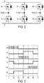
- Fig. 2 depicts a simplified circuit diagram of a three-phase inverter bridge and the corresponding PWM control signals to generate a six step commutated three phase voltage for BLDC motor control.
- This circuit may be provided as a part of the control unit 106. As shown in this figure, the circuit includes three high-side switches and three low-side switches. The switches may be, for example, Field Effect Transistors (FETs), in an embodiment. The gates of the FETs may be controlled by the micro-controller. The PHASE U, PHASE V, and PHASE W signals are provided to the terminals of the three-phase brushless motor 104.
- FETs Field Effect Transistors
- Fig. 3 depicts a waveform diagram of a conventional control mechanism of the three-phase inventor bridge of Fig. 2 .
- high-side FETs are used for Pulse Width Modulation (PWM) for motor speed control.
- PWM Pulse Width Modulation
- the corresponding low-side FETs are kept low.
- the issue with this conventional control mechanism is the amount of power loss in the FETs.
- the power losses are explained in detail below with respect to the U phase FETs.
- the U phase FETs are used as an example, but it must be understood that the FETs in the other two phases experience similar power losses.
- the high side FET is subject to conduction loss and switching loss.
- the conduction loss is a function of the duty cycle of the PWM control and the ON resistance of the FET.
- the switching loss is a function of the PWM frequency.
- the low side FET itself will have zero power loss as it was OFF during this period. However, the low side diode associated with the low side FET will dissipate power. This power loss is a function of the duty cycle of the PWM control and the PWM frequency.
- the high side FET and the diode do not have considerable power loss contribution, but the low side FET is continuously conducting in order to provide a return path for the current from the V (between 180 to 240 degrees) and W (between 240 to 300 degrees) high-side FETs.
- the low-side FET is thus subject to conduction loss that is a function of its ON resistance.
- an improved BLDC control technique is disclosed. This technique minimizes the power loss on the inverter bridge by shunting the diode currents using the adjacent FETS. Since power MOSFETs have typically very low ON resistance (i.e., drain to source voltage) compared to ON resistance (i.e., the forward voltage drop) of a diode, the power loss associated with a FET for equal amount of current flow is very comparatively low.
- the FETs are controlled more efficiently so as to minimize the power losses on the overall system in two ways.
- the low-side FETs are controlled with synchronous rectification. As the high-side FET is being toggled high and low during the PWM cycle, the low-side FET is oppositely toggled low and high during the same cycle.
- a special commutation edge pulse is introduced during cycles where both the high-side and low-side FETs are OFF.
- the high side FET is subject to conduction loss that is a function of the duty cycle of the PWM.
- the high-side FET is also subject to switching loss that is a function of the PWM frequency.
- the low-side FET is switched with synchronous rectification, allowing the OFF cycle current to flow through the low-side FET rather than the low-side diode.
- the FET has less voltage drop than the diode and thus results in less power loss.
- a special commutation edge pulse 1502 is introduced for a brief moment in the low-side FET following the last low cycle of the PWM cycle, according to an embodiment.
- the motor winding current in this embodiment is shunted by the special commutation edge pulse 1502, turning the low side FET ON for a brief cycle. Absent the edge pulse, this current would flow through the low side diode, which would result in higher power dissipation.
- the width of the edge pulse 1502 may be preprogrammed in software, or it may be dynamically calculated via the control unit as a function of the peak current or the resistance and inductance of the flow path. The width of the edge pulse 1502 may alternatively be implemented in a look-up table used by the control unit.
- the motor winding current is shunted by a second special commutation pulse 1504, turning the high-side FET ON for a brief cycle. Absent the edge pulse 1504, the motor current would flow through the high side diode, resulting in higher power dissipation.
- the width of the pulse is once again either calculated or tabulated by the control unit based on the peak current, the resistance and the inductance of the current path.
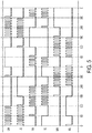
- Figs. 5 and 6A-6D Another aspect of this disclosure is discussed herein with reference to Figs. 5 and 6A-6D , according to an embodiment.
- the low-side FET is subject to conduction loss as a function of its turn ON resistance.
- the low-side FETs of the other two phases V and W similarly experience conduction losses during their respective ON cycles.
- an improved switching control scheme is provided as illustrated in the diagram of Fig. 5 .
- the continuous ON cycle is distributed between the high and the low-side FETS.
- the U phase for example
- the continuous ON cycle is assigned to the high-side FET.
- the high-side FET is turned continuously ON while the low-side FET is OFF for the first 120 degrees. Both FETs are then OFF continuously, subject to a small period where an edge pulse is introduced for the low-side FET, between 120-180 degrees.
- the low-side FET is then used for PWM control, with the high-side FET being controlled for synchronously rectification, between 180 to 300 degrees.
- both FETs are OFF, subject to an edge pulse for the high-side FET, between 300-360 degrees.
- a subsequent third cycle in this embodiment (not shown) will be controlled similarly to the first cycle, and so on. In this manner, the ON cycle and the resulting conduction loss associated therewith is shared between the low-side and high-side FETs. This helps reduce the overall stress on FETs as high-side and low-side FETs carry equal portion of the loss.
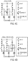
- Figs. 6A-6B illustrate the current path through the FETs and the motor windings during the first 120 degrees for of the first cycle
- Figs. 6C and 6D illustrate the current path during the first 120 degrees of the second cycle, according to an exemplary embodiment.
- the high-side FET of the U phase is used for PWM control and the current path continues through either the V or the W phase low-side FETs.
- the low-side FETs of the V and W phases are used for PWM control while the current path is carried through the high-side FET of the U phase.
- the current path of Fig. 6A is identical to the current path of Fig. 6C .
- the current path of Fig. 6B is identical to the current path of Fig. 6D . Accordingly, though a different set of FETs are used for PWM control in the second cycle, the current path remains virtually unchanged.
Description
- This disclosure relates to a power tool, and more particularly to commutation control an electric brushless DC motor for a power tool.
- The use of cordless power tools has increased dramatically in recent years. Cordless power tools provide the ease of a power assisted tool with the convenience of cordless operation. Conventionally, cordless tools have been driven by Permanent Magnet (PM) brushed motors that receive DC power from a battery assembly or converted AC power. The motor associated with a cordless tool has a direct impact on many of the operating characteristics of the tool, such as output torque, time duration of operation between charges and durability of the tool. The torque output relates to the capability of the power tool to operate under greater loads without stalling. The time duration of the power tool operation is strongly affected by the energy efficiency of the motor. Since, during some operating modes cordless tools are powered by battery modules that contain a limited amount of energy, the greater the energy efficiency of the motor, the longer the time duration that the tool can be operated. The durability of a power tool is affected by many factors, including the type of motor that is used to convert electrical power into mechanical power.
- Brushed motors such as the PM brushed motors that are generally employed in power tool applications are susceptible to damaged brushes over time. The main mechanical characteristic that separates Permanent Magnet brushless motors from Permanent Magnet brushed motors is the method of commutation. In a PM brushed motor, commutation is achieved mechanically via a commutator and a brush system. Whereas, in a brushless DC motor, commutation is achieved electronically by controlling the flow of current to the stator windings. A brushless DC motor includes a rotor for providing rotational energy and a stator for supplying a magnetic field that drives the rotor. Comprising the rotor is a shaft supported by a bearing set on each end and encircled by a permanent magnet (PM) that generates a magnetic field. The stator core includes field windings around the rotor. Power devices such as MOSFETs are connected in series with each winding to enable power to be selectively applied. When power is applied to a winding, the resulting current in the winding generates a magnetic field that couples to the rotor. The magnetic field associated with the PM in the rotor assembly attempts to align itself with the stator generated magnetic field resulting in rotational movement of the rotor. A control circuit sequentially activates the individual stator coils so that the PM attached to the rotor continuously chases the advancing magnetic field generated by the stator windings. A set of sense magnets coupled to the PMs in the rotor assembly are sensed by a sensor, such as a Hall Effect sensor, to identify the current position of the rotor assembly. Proper timing of the commutation sequence is maintained by monitoring sensors mounted on the rotor shaft or detecting magnetic field peaks or nulls associated with the PM.
- The power components, i.e,. MOSFETs, generally generate a significant amount of heat due to considerable power dissipation. For this reason, the power components are typically mounted in close proximity to a heat sink constructed to carry heat away from the power components. Heat generation is particularly problematic in high power/ high speed power tools. What is needed is an effective way of reducing the amount of power dissipation and heat generated by the power components.
-
JP 2004 201453 A - According to the present invention, there is provided a power tool according to claim 1.
- A power tool is provided. The power tool may be, for example, a drill or an impact driver, although other types of power tools may also be used. The power tool includes a housing and a brushless direct current (BLDC) motor housed inside the housing. The motor includes a stator assembly and a rotor pivotably arranged inside the stator. The power tool also includes high-side and low-side switches arranged between a power source and the motor and configured as a three-phase bridge to commutate the motor, each phase of the bridge being connected to a corresponding phase of the stator.
- A control unit is provided within the power tool. The control unit is configured to provide drive signals to drive each of the high-side and low-side switches to control, for each phase of the bridge, a pulse-width modulation (PWM) of one of the high-side or low-side switches. For each phase of the bridge, immediately following a first cycle ending with a falling edge of the drive signal for one of the high-side or low-side switches, the control unit introduces a special commutation edge pulse in the drive signal of the other of the high-side or low-side switches to shunt the current from the motor before turning both the high-side and the low-side switches off during a second cycle.
- For each phase of the bridge, the control unit is configured to control the PWM of the high-side switch and synchronous rectification of the low-side switch during the first cycle. The control unit is configured to introduce the special commutation edge pulse in the drive signal for the low-side switch during the second cycle.
- For each phase of the bridge, the control unit is configured to keep the high-side switch OFF and the low-side switch ON during the first cycle. Z The control unit is configured to introduce the special commutation edge pulse in the drive signal for the high-side switch during the second cycle.
- The control unit is configured to determine a width of the special commutation edge pulse as a function of either a peak current or a resistance and inductance of the current flow path.
- The drawings described herein are for illustration purposes only and are not intended to limit the scope of this disclosure in any way:
-
FIG. 1 depicts a perspective cross-sectional view of a power tool, according to an embodiment of this disclosure; -
Fig. 2 depicts a simplified circuit diagram of a three-phase inverter bridge and the corresponding PWM control signals to generate a six step commutated three phase voltage for BLDC motor control; -
Fig. 3 depicts a waveform diagram of a conventional commutation control mechanism of the three-phase inventor bridge ofFig. 2 ; -
Fig. 4 depicts a waveform diagram of a motor commutation control mechanism according to an embodiment of this disclosure; -
Fig. 5 depicts a waveform diagram of a motor commutation control mechanism according to a second aspect of this disclosure; -
Figs. 6A-6D depict simplified circuit diagrams showing current paths of various phases of the motor during different cycles of the waveform diagram ofFig. 5 . - With reference to the
Figure 1 , a power tool 100 constructed in accordance with the teachings of the present disclosure is illustrated in a longitudinal cross-section view. The power tool 100 in the particular example provided may be a drill/driver, but it will be appreciated that the teachings of this disclosure is merely exemplary and the power tool of this invention could be a circular saw, a reciprocating saw, or any similar portable power tool constructed in accordance with the teachings of this disclosure. Moreover, the output of the power tool driven (at least partly) by a transmission constructed in accordance with the teachings of this disclosure need not be in a rotary direction. - The power tool shown in
FIG. 1 may include ahousing assembly 102, amotor assembly 104, acontrol module 106, abattery pack 108, an input unit (e.g., a variable speed trigger) 110, atransmission assembly 114, an output spindle (not shown), and a chuck (not shown) that can be coupled for rotation with the output spindle. Thehousing assembly 102 can include ahousing 102a and agear case 102b that can be removably coupled to thehousing 102a. Thehousing 102a can define a housing body and ahandle 112. - According to an embodiment, the
motor 104 is received in thehousing 102a. The motor can be any type of motor and may be powered by an appropriate power source (electricity, pneumatic power, hydraulic power). In the particular example provided, the motor is a brushless DC electric motor and is powered by abattery pack 108. Aninput unit 110 is mounted in thehandle 112 below thehousing 102a. Theinput unit 110 may be a variable speed trigger switch, although other input means such as a touch-sensor, a capacitive-sensor, a speed dial, etc. may also be utilized. In an embodiment, variable speed trigger switch may integrate the ON/OFF, Forward/Reverse, and variable-speed functionalities into a single unit and provide respective inputs of these functions to thecontrol unit 106. Thecontrol unit 106, which is coupled to theinput unit 110, supplies the drive signals to the motor. In the exemplary embodiment of the invention, thecontrol unit 106 is provided in thehandle 112. - Construction details of the
brushless motor 104 or thecontrol unit 106 are beyond the scope of this disclosure, and can be found in co-pending International Patent Publication No.WO/2011159674 by the same assignee as this application. Thebrushless motor 104 depicted inFig. 1 is commutated electronically by thecontrol unit 106. The tool 100 is powered by a suitable power source such as thebattery pack 108. It is envisioned, however, that the present disclosures can be applied to a power tool with an AC power source, which may further include an AC-to-DC converter to power to motor. Using the variable-speed input and other inputs from theinput unit 110, thecontrol unit 106 controls the amount of power supplied to themotor 104. In an exemplary embodiment, thecontrol unit 106 controls the Pulse Width Modulation (PWM) duty cycle of the DC power supplied to themotor 104. Thecontrol unit 106, - in an embodiment, includes a micro-controller or other programmable processing unit to control supply of DC power to the
motor 104 and electrically commutate themotor 104. -
Fig. 2 depicts a simplified circuit diagram of a three-phase inverter bridge and the corresponding PWM control signals to generate a six step commutated three phase voltage for BLDC motor control. This circuit may be provided as a part of thecontrol unit 106. As shown in this figure, the circuit includes three high-side switches and three low-side switches. The switches may be, for example, Field Effect Transistors (FETs), in an embodiment. The gates of the FETs may be controlled by the micro-controller. The PHASE U, PHASE V, and PHASE W signals are provided to the terminals of the three-phase brushless motor 104. -
Fig. 3 depicts a waveform diagram of a conventional control mechanism of the three-phase inventor bridge ofFig. 2 . As shown in this figure, high-side FETs are used for Pulse Width Modulation (PWM) for motor speed control. During the PWM cycle of the high-side FETs, the corresponding low-side FETs are kept low. The issue with this conventional control mechanism is the amount of power loss in the FETs. The power losses are explained in detail below with respect to the U phase FETs. The U phase FETs are used as an example, but it must be understood that the FETs in the other two phases experience similar power losses. - From 0 to 120 degrees: The high side FET is subject to conduction loss and switching loss. The conduction loss is a function of the duty cycle of the PWM control and the ON resistance of the FET. The switching loss is a function of the PWM frequency. Meanwhile, the low side FET itself will have zero power loss as it was OFF during this period. However, the low side diode associated with the low side FET will dissipate power. This power loss is a function of the duty cycle of the PWM control and the PWM frequency.
- From 120 to 180 degrees: Both the high and low side FETs are turned OFF. However, as found by the inventors, there is significant power loss on the diode of the low side FET at the very beginning of this period, because the motor winding current decays from its high value down to zero through the low side diode.
- From 180 to 300 degree: The high side FET and the diode do not have considerable power loss contribution, but the low side FET is continuously conducting in order to provide a return path for the current from the V (between 180 to 240 degrees) and W (between 240 to 300 degrees) high-side FETs. The low-side
FET is thus subject to conduction loss that is a function of its ON resistance. - From 300 to 360 degree: Both the high and low side FETs are turned OFF in this sector. However, there is significant power loss on the beginning of the cycle as the current of the motor winding decays back to zero through the high side diode.
- Referring now to
Fig. 4 , an improved BLDC control technique is disclosed. This technique minimizes the power loss on the inverter bridge by shunting the diode currents using the adjacent FETS. Since power MOSFETs have typically very low ON resistance (i.e., drain to source voltage) compared to ON resistance (i.e., the forward voltage drop) of a diode, the power loss associated with a FET for equal amount of current flow is very comparatively low. - According to an embodiment of the invention, in order to reduce the power dissipation associated with the FETs in the circuit diagram of
Fig. 2 , a control method and technique is provided, which will be discussed herein with reference to the waveform diagram ofFig. 4 . In this diagram, the FETs are controlled more efficiently so as to minimize the power losses on the overall system in two ways. First, according to an embodiment, during the PWM cycles of the high-side FETs, the low-side FETs are controlled with synchronous rectification. As the high-side FET is being toggled high and low during the PWM cycle, the low-side FET is oppositely toggled low and high during the same cycle. Second, according to an embodiment, a special commutation edge pulse is introduced during cycles where both the high-side and low-side FETs are OFF. These improvements are discussed below in further detail, once again with respect to the U phase as an example, according to an embodiment of the invention. - From 0 to 120 degrees: As discussed above, the high side FET is subject to conduction loss that is a function of the duty cycle of the PWM. The high-side FET is also subject to switching loss that is a function of the PWM frequency. At the same time, in an embodiment, the low-side FET is switched with synchronous rectification, allowing the OFF cycle current to flow through the low-side FET rather than the low-side diode. The FET has less voltage drop than the diode and thus results in less power loss.
- From 120 to 180 degrees: At the beginning of this period, a special
commutation edge pulse 1502 is introduced for a brief moment in the low-side FET following the last low cycle of the PWM cycle, according to an embodiment. The motor winding current in this embodiment is shunted by the special commutation
edge pulse 1502, turning the low side FET ON for a brief cycle. Absent the edge pulse, this current would flow through the low side diode, which would result in higher power dissipation. In an embodiment, the width of theedge pulse 1502 may be preprogrammed in software, or it may be dynamically calculated via the control unit as a function of the peak current or the resistance and inductance of the flow path. The width of theedge pulse 1502 may alternatively be implemented in a look-up table used by the control unit. - From 180 to 300 degree: During the low-side FET ON cycle, the high-side FET and diode will not have any power loss contribution. The low-side FET is subject to conduction loss.
- From 300 to 360 degree: At the beginning of this period, the motor winding current is shunted by a second
special commutation pulse 1504, turning the high-side FET ON for a brief cycle. Absent theedge pulse 1504, the motor current would flow through the high side diode, resulting in higher power dissipation. The width of the pulse is once again either calculated or tabulated by the control unit based on the peak current, the resistance and the inductance of the current path. - It was found by the inventors that the reduction of the total power loss resulting from passing the current through the low-side and high-side FETs rather than the associated diodes during the special
commutation edge pulses Fig. 2 . This technique thus improves the overall tool performance. - Another aspect of this disclosure is discussed herein with reference to
Figs. 5 and6A-6D , according to an embodiment. As discussed above, during the low-side FET continuous ON cycles, e.g., between 180 to 300 degrees for phase U, the low-side FET is subject to conduction loss as a function of its turn ON resistance. The low-side FETs of the other two phases V and W similarly experience conduction losses during their respective ON cycles. In order to distribute the power conduction losses between the high-side and low-side FETs, according to an embodiment of the invention, an improved switching control scheme is provided as illustrated in the diagram ofFig. 5 . - In this embodiment, the continuous ON cycle is distributed between the high
and the low-side FETS. During a first full 360 degree cycle, the U phase (for example) is controlled as described above with reference toFig. 4 . In a subsequent second cycle, however, the continuous ON cycle is assigned to the high-side FET. Specifically, in the second full cycle, in an exemplary embodiment, the high-side FET is turned continuously ON while the low-side FET is OFF for the first 120 degrees. Both FETs are then OFF continuously, subject to a small period where an edge pulse is introduced for the low-side FET, between 120-180 degrees. The low-side FET is then used for PWM control, with the high-side FET being controlled for synchronously rectification, between 180 to 300 degrees. Finally, both FETs are OFF, subject to an edge pulse for the high-side FET, between 300-360 degrees. A subsequent third cycle in this embodiment (not shown) will be controlled similarly to the first cycle, and so on. In this manner, the ON cycle and the resulting conduction loss associated therewith is shared between the low-side and high-side FETs. This helps reduce the overall stress on FETs as high-side and low-side FETs carry equal portion of the loss. - It is noted that the PWM cycle of the V phase is split two 60 degree cycles between 0 to 60 degrees and 300 to 360 degrees in order to accommodate this modification. It is also noted that even though the PWM control in this embodiment is different from one cycle to the next, the current flow through the motor is effectively remains unchanged.
Figs. 6A-6B illustrate the current path through the FETs and the motor windings during the first 120 degrees for of the first cycle, whereasFigs. 6C and 6D illustrate the current path during the first 120 degrees of the second cycle, according to an exemplary embodiment. As shown InFigs. 6A and 6B , in the first cycle, the high-side FET of the U phase is used for PWM control and the current path continues through either the V or the W phase low-side FETs. During the second cycle, as shown inFigs. 6C and 6D , the low-side FETs of the V and W phases are used for PWM control while the current path is carried through the high-side FET of the U phase. The current path ofFig. 6A is identical to the current path ofFig. 6C . Similarly, the current path ofFig. 6B is identical to the current path ofFig. 6D . Accordingly, though a different set of FETs are used for PWM control in the second cycle, the current path remains virtually unchanged.
Claims (3)
- A power tool comprising:a housing (102);a brushless direct current (BLDC) motor (104) housed inside the housing, the motor including a stator and a rotor pivotably arranged inside the stator;a plurality of high-side and low-side switches arranged between a power source (108) and the motor and configured as a three-phase bridge to commutate the motor, each phase of the bridge being connected to a corresponding phase of the stator;a control unit (106) configured to provide drive signals (UH, UL, VH, VL, WH, WL) to drive each of the high-side and low-side switches to control, for each phase of the bridge, a pulse-width modulation (PWM) of the high-side and low-side switches, and immediately following a first duty cycle ending with a falling edge of the drive signal for the high-side switches, to introduce a first special commutation edge pulse (1502) in the drive signal of the low-side switches to shunt the current from the motor before turning both the high-side and the low-side switches off during a second duty cycle;characterized in that, when the low-side switch is on, the control unit is further configured to introduce a second special commutation pulse (1504) to the high-side switch to turn the high-side switch ON for a brief cycle in a third duty cycle when the low-side switch is switched off to shunt the motor winding current;wherein the control unit is configured to determine a width at least one of the first and second special commutation edge pulses as a function of either a peak current or a resistance and inductance of the current flow path.
- The power tool of claim 1, wherein for each phase of the bridge, the control unit is configured to control the PWM of the high-side switch and to oppositely toggle the low-side switch low and high during the same duty cycle.
- The power tool of claim 2, wherein the control unit is configured to introduce the special commutation edge pulse in the drive signal for the low-side switch during the second duty cycle.
Applications Claiming Priority (1)
| Application Number | Priority Date | Filing Date | Title |
|---|---|---|---|
| US201261660335P | 2012-06-15 | 2012-06-15 |
Publications (3)
| Publication Number | Publication Date |
|---|---|
| EP2674256A2 EP2674256A2 (en) | 2013-12-18 |
| EP2674256A3 EP2674256A3 (en) | 2017-08-23 |
| EP2674256B1 true EP2674256B1 (en) | 2021-11-10 |
Family
ID=48628337
Family Applications (3)
| Application Number | Title | Priority Date | Filing Date |
|---|---|---|---|
| EP13172319.9A Active EP2674256B1 (en) | 2012-06-15 | 2013-06-17 | Brushless motor commutation control in a power tool |
| EP13172315.7A Active EP2675041B1 (en) | 2012-06-15 | 2013-06-17 | Stator assembly for a brushless motor in a power tool |
| EP13172314.0A Withdrawn EP2675040A3 (en) | 2012-06-15 | 2013-06-17 | Stator assembly for a Brushless motor in a power tool |
Family Applications After (2)
| Application Number | Title | Priority Date | Filing Date |
|---|---|---|---|
| EP13172315.7A Active EP2675041B1 (en) | 2012-06-15 | 2013-06-17 | Stator assembly for a brushless motor in a power tool |
| EP13172314.0A Withdrawn EP2675040A3 (en) | 2012-06-15 | 2013-06-17 | Stator assembly for a Brushless motor in a power tool |
Country Status (2)
| Country | Link |
|---|---|
| US (2) | US20130342041A1 (en) |
| EP (3) | EP2674256B1 (en) |
Families Citing this family (30)
| Publication number | Priority date | Publication date | Assignee | Title |
|---|---|---|---|---|
| US11770048B2 (en) | 2013-10-18 | 2023-09-26 | Black & Decker, Inc. | Handheld power tool with a brushless electric motor |
| JP6274415B2 (en) | 2014-02-27 | 2018-02-07 | 日立工機株式会社 | Electric tool |
| CN104362935B (en) * | 2014-11-10 | 2016-12-07 | 无锡普雅半导体有限公司 | A kind of power driving circuit suppressing current impulse |
| EP3197025B1 (en) | 2014-11-25 | 2020-10-28 | Black & Decker Inc. | Brushless motor for a power tool |
| US10693344B2 (en) | 2014-12-18 | 2020-06-23 | Black & Decker Inc. | Packaging of a control module for a brushless motor |
| US10348158B2 (en) * | 2015-02-04 | 2019-07-09 | Makita Corporation | Power tool |
| EP3086443B1 (en) * | 2015-04-22 | 2022-02-23 | Goodrich Actuation Systems Limited | Electromechanical actuator damping |
| WO2016196984A1 (en) * | 2015-06-05 | 2016-12-08 | Ingersoll-Rand Company | Power tools with user-selectable operational modes |
| US10328567B2 (en) | 2015-10-14 | 2019-06-25 | Black & Decker Inc. | Brushless motor system for power tools |
| EP3385035B1 (en) | 2015-10-30 | 2020-05-27 | Black & Decker Inc. | Control and power module for driving a brushless motor in a power tool |
| WO2017079295A1 (en) * | 2015-11-02 | 2017-05-11 | Black & Decker Inc. | Reducing noise and lowering harmonics in power tools using conduction band control schemes |
| JP6493164B2 (en) | 2015-11-06 | 2019-04-03 | 株式会社デンソー | Rotating electric machine drive system |
| EP3292959B1 (en) | 2016-02-12 | 2021-06-16 | Black & Decker Inc. | Electronic braking for a power tool having a brushless motor |
| US10523087B2 (en) | 2016-06-24 | 2019-12-31 | Black & Decker Inc. | Control scheme for operating cordless power tool based on battery temperature |
| US10835972B2 (en) | 2018-03-16 | 2020-11-17 | Milwaukee Electric Tool Corporation | Blade clamp for power tool |
| US11014176B2 (en) | 2018-04-03 | 2021-05-25 | Milwaukee Electric Tool Corporation | Jigsaw |
| USD887806S1 (en) | 2018-04-03 | 2020-06-23 | Milwaukee Electric Tool Corporation | Jigsaw |
| CN110434791B (en) * | 2018-05-03 | 2021-08-27 | 南京德朔实业有限公司 | Impact screwdriver and electric tool |
| US11489477B2 (en) | 2018-06-15 | 2022-11-01 | Mirka Oy | Semi-symmetric switching |
| WO2020113056A1 (en) | 2018-11-29 | 2020-06-04 | Milwaukee Electric Tool Corporation | Motor winding design for an electric motor |
| EP4220914A1 (en) | 2019-01-15 | 2023-08-02 | Black & Decker, Inc. | Power module for a brushless motor in a power tool |
| EP3806273A1 (en) | 2019-10-11 | 2021-04-14 | Black & Decker Inc. | Power tool receiving different capacity batttery packs |
| WO2021119229A1 (en) | 2019-12-10 | 2021-06-17 | Milwaukee Electric Tool Corporation | Motor control for gas engine replacement device based on battery pack configuration data |
| EP4078787A4 (en) | 2019-12-20 | 2023-11-22 | Milwaukee Electric Tool Corporation | Gas engine replacement electronics modularity for feature expansion |
| EP4133581A1 (en) | 2020-04-10 | 2023-02-15 | Milwaukee Electric Tool Corporation | Adapter for configuring gas engine replacement device |
| EP4140020A1 (en) | 2020-04-21 | 2023-03-01 | Milwaukee Electric Tool Corporation | Power tool printed circuit board including embedded busbars |
| US11811287B2 (en) | 2020-06-05 | 2023-11-07 | Milwaukee Electric Tool Corporation | Brushless motor for a power tool |
| US20220200401A1 (en) | 2020-12-23 | 2022-06-23 | Black & Decker Inc. | Brushless dc motor with circuit board for winding interconnections |
| US11689124B2 (en) | 2021-01-12 | 2023-06-27 | Snap-On Incorporated | Controlling brushless motor commutation |
| CN216981644U (en) * | 2021-08-25 | 2022-07-15 | 米沃奇电动工具公司 | Electric motor and electric tool including the same |
Family Cites Families (25)
| Publication number | Priority date | Publication date | Assignee | Title |
|---|---|---|---|---|
| US3334255A (en) * | 1965-02-19 | 1967-08-01 | Robert W Peters | Electric motor |
| JPH06113500A (en) * | 1992-09-30 | 1994-04-22 | Aisin Seiki Co Ltd | Insulator |
| JP3440782B2 (en) * | 1997-10-29 | 2003-08-25 | 三菱電機株式会社 | Reluctance motor and reluctance motor for driving compressor |
| AU2001284010A1 (en) | 2000-08-30 | 2002-03-13 | Papst-Motoren Gmbh And Co. Kg | Fan arrangement |
| JP3603784B2 (en) * | 2000-12-14 | 2004-12-22 | 日産自動車株式会社 | Rotating electric machine |
| JP3624825B2 (en) * | 2000-12-14 | 2005-03-02 | 日産自動車株式会社 | Rotating electric machine and method of manufacturing rotating electric machine |
| JP4923374B2 (en) * | 2001-09-26 | 2012-04-25 | 日産自動車株式会社 | Stator structure of rotating electrical machine |
| US6906485B2 (en) | 2001-11-05 | 2005-06-14 | Seagate Technology Llc | Spindle motor control using a current profile to taper current transitions |
| GB0130602D0 (en) * | 2001-12-21 | 2002-02-06 | Johnson Electric Sa | Brushless D.C. motor |
| US6781853B2 (en) | 2002-03-13 | 2004-08-24 | Virginia Tech Intellectual Properties, Inc. | Method and apparatus for reduction of energy loss due to body diode conduction in synchronous rectifiers |
| JP2004201453A (en) * | 2002-12-20 | 2004-07-15 | Nissan Motor Co Ltd | Drive unit of direct-current, three-phase brushless motor |
| DE10261611A1 (en) * | 2002-12-27 | 2004-07-08 | Robert Bosch Gmbh | Connection element for a winding of an electrical machine |
| JP4749663B2 (en) | 2003-12-01 | 2011-08-17 | 株式会社マキタ | Motor control device |
| JP2006320136A (en) * | 2005-05-13 | 2006-11-24 | Mitsubishi Electric Corp | Stator for dynamo-electric machine |
| JP2008024171A (en) * | 2006-07-21 | 2008-02-07 | Jtekt Corp | Electric power steering device |
| EP1947755B1 (en) * | 2007-01-19 | 2009-11-18 | ENGEL Elektroantriebe GmbH | Stator of an electric machine |
| US8253285B2 (en) * | 2007-04-27 | 2012-08-28 | Hitachi Koki Co., Ltd. | Power tool |
| JP5116490B2 (en) * | 2008-01-08 | 2013-01-09 | 株式会社マキタ | Motor control device and electric tool using the same |
| JP5170165B2 (en) | 2010-06-11 | 2013-03-27 | 株式会社村田製作所 | Isolated switching power supply |
| US10056806B2 (en) * | 2010-06-14 | 2018-08-21 | Black & Decker Inc. | Stator assembly for a brushless motor in a power tool |
| US8356869B2 (en) | 2010-06-25 | 2013-01-22 | Xerox Corporation | Body diode forward conduction prevention |
| DE102010060859A1 (en) * | 2010-11-29 | 2012-05-31 | Thyssenkrupp Aufzugswerke Gmbh | elevator drive |
| US9406457B2 (en) * | 2011-05-19 | 2016-08-02 | Black & Decker Inc. | Electronic switching module for a power tool |
| US9193055B2 (en) * | 2012-04-13 | 2015-11-24 | Black & Decker Inc. | Electronic clutch for power tool |
| GB2515080B (en) * | 2013-06-13 | 2016-02-24 | Dyson Technology Ltd | Controller for a brushless motor |
-
2013
- 2013-06-17 EP EP13172319.9A patent/EP2674256B1/en active Active
- 2013-06-17 US US13/919,413 patent/US20130342041A1/en not_active Abandoned
- 2013-06-17 US US13/919,477 patent/US9154009B2/en active Active
- 2013-06-17 EP EP13172315.7A patent/EP2675041B1/en active Active
- 2013-06-17 EP EP13172314.0A patent/EP2675040A3/en not_active Withdrawn
Non-Patent Citations (1)
| Title |
|---|
| None * |
Also Published As
| Publication number | Publication date |
|---|---|
| US20130342144A1 (en) | 2013-12-26 |
| EP2675041A3 (en) | 2017-11-01 |
| US9154009B2 (en) | 2015-10-06 |
| EP2674256A2 (en) | 2013-12-18 |
| EP2674256A3 (en) | 2017-08-23 |
| EP2675041B1 (en) | 2020-05-13 |
| EP2675040A2 (en) | 2013-12-18 |
| EP2675041A2 (en) | 2013-12-18 |
| EP2675040A3 (en) | 2017-10-11 |
| US20130342041A1 (en) | 2013-12-26 |
Similar Documents
| Publication | Publication Date | Title |
|---|---|---|
| EP2674256B1 (en) | Brushless motor commutation control in a power tool | |
| EP2433757B1 (en) | Power tool and method of controlling a motor inside a power tool | |
| US10177691B2 (en) | Electronic braking of brushless DC motor in a power tool | |
| JP5942500B2 (en) | Electric tool | |
| EP2714339B1 (en) | Control system for a fastening power tool | |
| JP5743085B2 (en) | Electric tool | |
| EP3035516A2 (en) | Packaging of a control module for a brushless motor | |
| US20130264987A1 (en) | Electric power tool | |
| JP6090581B2 (en) | Electric tool | |
| JP2009202317A (en) | Electric rotating tool | |
| EP2048774A3 (en) | Rotary electric system with star-connected multiphase stator windings | |
| CN111630770B (en) | Electric tool and control method thereof | |
| WO2013081191A2 (en) | Electric tool | |
| US20230108641A1 (en) | Power tool receiving different capacity battery packs | |
| Bharatkar et al. | Reduction of commutation torque ripple in a brushless DC motor drive | |
| CN113785485A (en) | Sensorless motor control for power tools | |
| WO2018082496A1 (en) | Electric tool and control method therefor | |
| JP2004023823A (en) | Controller of brushless dc motor | |
| JP4349777B2 (en) | Cordless power tool | |
| JP2004015986A (en) | Control device of motor | |
| EP4307555A1 (en) | Power tool | |
| WO2012064693A2 (en) | Lossless snubber drive for a permanent magnet synchronous motor | |
| US20230411978A1 (en) | Battery pack identification in power tool | |
| CN116683404A (en) | Electric tool and control method thereof |
Legal Events
| Date | Code | Title | Description |
|---|---|---|---|
| PUAI | Public reference made under article 153(3) epc to a published international application that has entered the european phase |
Free format text: ORIGINAL CODE: 0009012 |
|
| AK | Designated contracting states |
Kind code of ref document: A2 Designated state(s): AL AT BE BG CH CY CZ DE DK EE ES FI FR GB GR HR HU IE IS IT LI LT LU LV MC MK MT NL NO PL PT RO RS SE SI SK SM TR |
|
| AX | Request for extension of the european patent |
Extension state: BA ME |
|
| PUAL | Search report despatched |
Free format text: ORIGINAL CODE: 0009013 |
|
| AK | Designated contracting states |
Kind code of ref document: A3 Designated state(s): AL AT BE BG CH CY CZ DE DK EE ES FI FR GB GR HR HU IE IS IT LI LT LU LV MC MK MT NL NO PL PT RO RS SE SI SK SM TR |
|
| AX | Request for extension of the european patent |
Extension state: BA ME |
|
| RIC1 | Information provided on ipc code assigned before grant |
Ipc: H02K 3/34 20060101ALI20170714BHEP Ipc: H02P 29/00 20160101ALI20170714BHEP Ipc: H02K 7/14 20060101ALI20170714BHEP Ipc: B25F 5/00 20060101ALI20170714BHEP Ipc: B25D 17/00 20060101AFI20170714BHEP Ipc: H02P 6/12 20060101ALI20170714BHEP Ipc: H02P 27/08 20060101ALI20170714BHEP |
|
| STAA | Information on the status of an ep patent application or granted ep patent |
Free format text: STATUS: REQUEST FOR EXAMINATION WAS MADE |
|
| 17P | Request for examination filed |
Effective date: 20170830 |
|
| RBV | Designated contracting states (corrected) |
Designated state(s): AL AT BE BG CH CY CZ DE DK EE ES FI FR GB GR HR HU IE IS IT LI LT LU LV MC MK MT NL NO PL PT RO RS SE SI SK SM TR |
|
| STAA | Information on the status of an ep patent application or granted ep patent |
Free format text: STATUS: EXAMINATION IS IN PROGRESS |
|
| 17Q | First examination report despatched |
Effective date: 20191122 |
|
| STAA | Information on the status of an ep patent application or granted ep patent |
Free format text: STATUS: EXAMINATION IS IN PROGRESS |
|
| REG | Reference to a national code |
Ref country code: DE Ref legal event code: R079 Ref document number: 602013079964 Country of ref document: DE Free format text: PREVIOUS MAIN CLASS: B25D0017000000 Ipc: H02P0029680000 |
|
| RIC1 | Information provided on ipc code assigned before grant |
Ipc: H02P 29/68 20160101AFI20210507BHEP Ipc: B25F 5/00 20060101ALI20210507BHEP Ipc: H02P 27/08 20060101ALI20210507BHEP Ipc: H02P 6/12 20060101ALI20210507BHEP |
|
| GRAP | Despatch of communication of intention to grant a patent |
Free format text: ORIGINAL CODE: EPIDOSNIGR1 |
|
| STAA | Information on the status of an ep patent application or granted ep patent |
Free format text: STATUS: GRANT OF PATENT IS INTENDED |
|
| INTG | Intention to grant announced |
Effective date: 20210621 |
|
| GRAS | Grant fee paid |
Free format text: ORIGINAL CODE: EPIDOSNIGR3 |
|
| GRAA | (expected) grant |
Free format text: ORIGINAL CODE: 0009210 |
|
| STAA | Information on the status of an ep patent application or granted ep patent |
Free format text: STATUS: THE PATENT HAS BEEN GRANTED |
|
| AK | Designated contracting states |
Kind code of ref document: B1 Designated state(s): AL AT BE BG CH CY CZ DE DK EE ES FI FR GB GR HR HU IE IS IT LI LT LU LV MC MK MT NL NO PL PT RO RS SE SI SK SM TR |
|
| REG | Reference to a national code |
Ref country code: GB Ref legal event code: FG4D |
|
| REG | Reference to a national code |
Ref country code: AT Ref legal event code: REF Ref document number: 1447004 Country of ref document: AT Kind code of ref document: T Effective date: 20211115 Ref country code: CH Ref legal event code: EP |
|
| REG | Reference to a national code |
Ref country code: DE Ref legal event code: R096 Ref document number: 602013079964 Country of ref document: DE |
|
| REG | Reference to a national code |
Ref country code: IE Ref legal event code: FG4D |
|
| REG | Reference to a national code |
Ref country code: LT Ref legal event code: MG9D |
|
| REG | Reference to a national code |
Ref country code: NL Ref legal event code: MP Effective date: 20211110 |
|
| REG | Reference to a national code |
Ref country code: AT Ref legal event code: MK05 Ref document number: 1447004 Country of ref document: AT Kind code of ref document: T Effective date: 20211110 |
|
| PG25 | Lapsed in a contracting state [announced via postgrant information from national office to epo] |
Ref country code: RS Free format text: LAPSE BECAUSE OF FAILURE TO SUBMIT A TRANSLATION OF THE DESCRIPTION OR TO PAY THE FEE WITHIN THE PRESCRIBED TIME-LIMIT Effective date: 20211110 Ref country code: LT Free format text: LAPSE BECAUSE OF FAILURE TO SUBMIT A TRANSLATION OF THE DESCRIPTION OR TO PAY THE FEE WITHIN THE PRESCRIBED TIME-LIMIT Effective date: 20211110 Ref country code: FI Free format text: LAPSE BECAUSE OF FAILURE TO SUBMIT A TRANSLATION OF THE DESCRIPTION OR TO PAY THE FEE WITHIN THE PRESCRIBED TIME-LIMIT Effective date: 20211110 Ref country code: BG Free format text: LAPSE BECAUSE OF FAILURE TO SUBMIT A TRANSLATION OF THE DESCRIPTION OR TO PAY THE FEE WITHIN THE PRESCRIBED TIME-LIMIT Effective date: 20220210 Ref country code: AT Free format text: LAPSE BECAUSE OF FAILURE TO SUBMIT A TRANSLATION OF THE DESCRIPTION OR TO PAY THE FEE WITHIN THE PRESCRIBED TIME-LIMIT Effective date: 20211110 |
|
| PG25 | Lapsed in a contracting state [announced via postgrant information from national office to epo] |
Ref country code: IS Free format text: LAPSE BECAUSE OF FAILURE TO SUBMIT A TRANSLATION OF THE DESCRIPTION OR TO PAY THE FEE WITHIN THE PRESCRIBED TIME-LIMIT Effective date: 20220310 Ref country code: SE Free format text: LAPSE BECAUSE OF FAILURE TO SUBMIT A TRANSLATION OF THE DESCRIPTION OR TO PAY THE FEE WITHIN THE PRESCRIBED TIME-LIMIT Effective date: 20211110 Ref country code: PT Free format text: LAPSE BECAUSE OF FAILURE TO SUBMIT A TRANSLATION OF THE DESCRIPTION OR TO PAY THE FEE WITHIN THE PRESCRIBED TIME-LIMIT Effective date: 20220310 Ref country code: PL Free format text: LAPSE BECAUSE OF FAILURE TO SUBMIT A TRANSLATION OF THE DESCRIPTION OR TO PAY THE FEE WITHIN THE PRESCRIBED TIME-LIMIT Effective date: 20211110 Ref country code: NO Free format text: LAPSE BECAUSE OF FAILURE TO SUBMIT A TRANSLATION OF THE DESCRIPTION OR TO PAY THE FEE WITHIN THE PRESCRIBED TIME-LIMIT Effective date: 20220210 Ref country code: NL Free format text: LAPSE BECAUSE OF FAILURE TO SUBMIT A TRANSLATION OF THE DESCRIPTION OR TO PAY THE FEE WITHIN THE PRESCRIBED TIME-LIMIT Effective date: 20211110 Ref country code: LV Free format text: LAPSE BECAUSE OF FAILURE TO SUBMIT A TRANSLATION OF THE DESCRIPTION OR TO PAY THE FEE WITHIN THE PRESCRIBED TIME-LIMIT Effective date: 20211110 Ref country code: HR Free format text: LAPSE BECAUSE OF FAILURE TO SUBMIT A TRANSLATION OF THE DESCRIPTION OR TO PAY THE FEE WITHIN THE PRESCRIBED TIME-LIMIT Effective date: 20211110 Ref country code: GR Free format text: LAPSE BECAUSE OF FAILURE TO SUBMIT A TRANSLATION OF THE DESCRIPTION OR TO PAY THE FEE WITHIN THE PRESCRIBED TIME-LIMIT Effective date: 20220211 Ref country code: ES Free format text: LAPSE BECAUSE OF FAILURE TO SUBMIT A TRANSLATION OF THE DESCRIPTION OR TO PAY THE FEE WITHIN THE PRESCRIBED TIME-LIMIT Effective date: 20211110 |
|
| PG25 | Lapsed in a contracting state [announced via postgrant information from national office to epo] |
Ref country code: SM Free format text: LAPSE BECAUSE OF FAILURE TO SUBMIT A TRANSLATION OF THE DESCRIPTION OR TO PAY THE FEE WITHIN THE PRESCRIBED TIME-LIMIT Effective date: 20211110 Ref country code: SK Free format text: LAPSE BECAUSE OF FAILURE TO SUBMIT A TRANSLATION OF THE DESCRIPTION OR TO PAY THE FEE WITHIN THE PRESCRIBED TIME-LIMIT Effective date: 20211110 Ref country code: RO Free format text: LAPSE BECAUSE OF FAILURE TO SUBMIT A TRANSLATION OF THE DESCRIPTION OR TO PAY THE FEE WITHIN THE PRESCRIBED TIME-LIMIT Effective date: 20211110 Ref country code: EE Free format text: LAPSE BECAUSE OF FAILURE TO SUBMIT A TRANSLATION OF THE DESCRIPTION OR TO PAY THE FEE WITHIN THE PRESCRIBED TIME-LIMIT Effective date: 20211110 Ref country code: DK Free format text: LAPSE BECAUSE OF FAILURE TO SUBMIT A TRANSLATION OF THE DESCRIPTION OR TO PAY THE FEE WITHIN THE PRESCRIBED TIME-LIMIT Effective date: 20211110 Ref country code: CZ Free format text: LAPSE BECAUSE OF FAILURE TO SUBMIT A TRANSLATION OF THE DESCRIPTION OR TO PAY THE FEE WITHIN THE PRESCRIBED TIME-LIMIT Effective date: 20211110 |
|
| REG | Reference to a national code |
Ref country code: DE Ref legal event code: R097 Ref document number: 602013079964 Country of ref document: DE |
|
| PLBE | No opposition filed within time limit |
Free format text: ORIGINAL CODE: 0009261 |
|
| STAA | Information on the status of an ep patent application or granted ep patent |
Free format text: STATUS: NO OPPOSITION FILED WITHIN TIME LIMIT |
|
| 26N | No opposition filed |
Effective date: 20220811 |
|
| PG25 | Lapsed in a contracting state [announced via postgrant information from national office to epo] |
Ref country code: AL Free format text: LAPSE BECAUSE OF FAILURE TO SUBMIT A TRANSLATION OF THE DESCRIPTION OR TO PAY THE FEE WITHIN THE PRESCRIBED TIME-LIMIT Effective date: 20211110 |
|
| PG25 | Lapsed in a contracting state [announced via postgrant information from national office to epo] |
Ref country code: SI Free format text: LAPSE BECAUSE OF FAILURE TO SUBMIT A TRANSLATION OF THE DESCRIPTION OR TO PAY THE FEE WITHIN THE PRESCRIBED TIME-LIMIT Effective date: 20211110 |
|
| PG25 | Lapsed in a contracting state [announced via postgrant information from national office to epo] |
Ref country code: MC Free format text: LAPSE BECAUSE OF FAILURE TO SUBMIT A TRANSLATION OF THE DESCRIPTION OR TO PAY THE FEE WITHIN THE PRESCRIBED TIME-LIMIT Effective date: 20211110 |
|
| REG | Reference to a national code |
Ref country code: CH Ref legal event code: PL |
|
| REG | Reference to a national code |
Ref country code: BE Ref legal event code: MM Effective date: 20220630 |
|
| PG25 | Lapsed in a contracting state [announced via postgrant information from national office to epo] |
Ref country code: LU Free format text: LAPSE BECAUSE OF NON-PAYMENT OF DUE FEES Effective date: 20220617 Ref country code: LI Free format text: LAPSE BECAUSE OF NON-PAYMENT OF DUE FEES Effective date: 20220630 Ref country code: IE Free format text: LAPSE BECAUSE OF NON-PAYMENT OF DUE FEES Effective date: 20220617 Ref country code: FR Free format text: LAPSE BECAUSE OF NON-PAYMENT OF DUE FEES Effective date: 20220630 Ref country code: CH Free format text: LAPSE BECAUSE OF NON-PAYMENT OF DUE FEES Effective date: 20220630 |
|
| PG25 | Lapsed in a contracting state [announced via postgrant information from national office to epo] |
Ref country code: IT Free format text: LAPSE BECAUSE OF FAILURE TO SUBMIT A TRANSLATION OF THE DESCRIPTION OR TO PAY THE FEE WITHIN THE PRESCRIBED TIME-LIMIT Effective date: 20211110 Ref country code: BE Free format text: LAPSE BECAUSE OF NON-PAYMENT OF DUE FEES Effective date: 20220630 |
|
| PGFP | Annual fee paid to national office [announced via postgrant information from national office to epo] |
Ref country code: DE Payment date: 20230425 Year of fee payment: 11 |
|
| PGFP | Annual fee paid to national office [announced via postgrant information from national office to epo] |
Ref country code: GB Payment date: 20230427 Year of fee payment: 11 |
|
| PG25 | Lapsed in a contracting state [announced via postgrant information from national office to epo] |
Ref country code: HU Free format text: LAPSE BECAUSE OF FAILURE TO SUBMIT A TRANSLATION OF THE DESCRIPTION OR TO PAY THE FEE WITHIN THE PRESCRIBED TIME-LIMIT; INVALID AB INITIO Effective date: 20130617 |