JP6442250B2 - Brushless motor integrated pump - Google Patents
Brushless motor integrated pump Download PDFInfo
- Publication number
- JP6442250B2 JP6442250B2 JP2014238215A JP2014238215A JP6442250B2 JP 6442250 B2 JP6442250 B2 JP 6442250B2 JP 2014238215 A JP2014238215 A JP 2014238215A JP 2014238215 A JP2014238215 A JP 2014238215A JP 6442250 B2 JP6442250 B2 JP 6442250B2
- Authority
- JP
- Japan
- Prior art keywords
- motor
- working medium
- brushless motor
- rotor
- stator
- Prior art date
- Legal status (The legal status is an assumption and is not a legal conclusion. Google has not performed a legal analysis and makes no representation as to the accuracy of the status listed.)
- Expired - Fee Related
Links
Images


Description
本発明は、ランキンサイクルを初めとする、廃熱回収システムの作動媒体を圧送するための回転ポンプと、前記回転ポンプと回転軸を共用し、前記回転ポンプへ駆動力を付加するためのモータとを一体に有するブラシレスモータ一体型ポンプに関するものである。 The present invention includes a rotary pump for pumping a working medium of a waste heat recovery system such as a Rankine cycle, a motor for sharing the rotary pump and a rotary shaft, and adding a driving force to the rotary pump. The present invention relates to a brushless motor-integrated pump integrally having
昨今、廃熱回収システムの作動媒体などを圧送するために、ブラシレスモータにポンプを一体化して回転軸を共用する構造として、かつ高効率・高耐久性を実現可能なブラシレスモータ一体型ポンプが求められている。 In recent years, there is a need for a brushless motor-integrated pump capable of realizing high efficiency and high durability as a structure that integrates a pump with a brushless motor and shares a rotating shaft to pump the working medium of a waste heat recovery system. It has been.
従来、ステータとロータを有するブラシレスモータにおいては、その稼動時にステータに設けられたコイルが発熱することにより、コイル抵抗が増加し、余分な電流を要するために効率が低下するという問題があった。 Conventionally, a brushless motor having a stator and a rotor has a problem in that the coil provided in the stator generates heat during its operation, thereby increasing the coil resistance and requiring an extra current, thereby reducing the efficiency.
これに対して熱損失を回避しようとして仕様を変更する場合(例えば、大型化など)には、余計な重量・サイズ・費用が必要となる事があり、これを回避できるコイルの冷却方法が望まれていた。 On the other hand, when changing specifications to avoid heat loss (for example, increasing the size), extra weight, size, and cost may be required, and a coil cooling method that can avoid this is desired. It was rare.
そこで、例えば特開2002−165411号公報(特許文献1)に示すように、ステータコア外周に形成されたコイルの外周に冷却液通路を設け、モータ(または発電機)のステータとして設けられたコイルに対して周囲を冷却液が流通することで冷却することを可能とした発明が知られている。 Therefore, for example, as shown in JP-A-2002-165411 (Patent Document 1), a coolant passage is provided on the outer periphery of the coil formed on the outer periphery of the stator core, and the coil provided as the stator of the motor (or the generator) On the other hand, an invention that enables cooling by circulating a coolant around the periphery is known.
この特許文献1に記載された発明では、隔壁によりステータ側とロータ側とを隔離してステータ側にのみ冷却液を流通させることにより、回転駆動するロータ側には影響を与える事無くコイルの冷却を可能としたものである。
In the invention described in
さらに、例えば特開2009−19522号公報(特許文献2)に示されるように、電動モータを一体に備えた電動ポンプも知られており、この特許文献2に記載された電動ポンプとは、密閉型ハウジング内に設けられた電動モータと、吐出部と、吸入部とを備える電動ポンプにおいて、導入路と導出路を有し、前記冷却液ハウジング内より導出する冷却液導出手段とを更に有することを特徴とする電動ポンプである。
Furthermore, for example, as disclosed in Japanese Patent Application Laid-Open No. 2009-19522 (Patent Document 2), an electric pump integrally provided with an electric motor is also known. The electric pump described in
この特許文献2に記載された発明においては、ポンプによって加圧された液体がステータとロータを有するモータ内部に導入されることにより、モータ軸に取り付けられたベアリングの潤滑およびモータ内部のステータとロータの冷却を可能としつつ、明細書および図面に示された実施例の様に前記ポンプは既存の形式である内接歯車方式ポンプを用いることによって、ポンプ効率の低下を抑制しつつ効率の良いモータ冷却構造を提供することを可能としている。
In the invention described in
しかし、この特許文献2に記載された発明はステータとロータの両方を通過するように液体を流通させることでコイルの冷却を行うものだが、モータ内部を液体が通過する場合、液体の抵抗力によりロータの回転が阻害され、結果として効率低下へ繋がる場合がある。
However, the invention described in
よって、液体によるコイルの冷却を可能としつつ、ロータの回転を阻害しない構造を有するブラシレスモータ一体型ポンプが必要とされていた。 Therefore, there is a need for a brushless motor-integrated pump having a structure that does not hinder the rotation of the rotor while allowing the coil to be cooled by liquid.
また、前述のような廃熱回収システムの作動媒体などを圧送するブラシレスモータ一体型ポンプにあっては、コイルからの熱交換により前記作動媒体を加熱することで廃熱回収システムの効率向上ならびにモータコイル温度の抑制を可能とするものが特に望まれていた。 Further, in the brushless motor-integrated pump that pumps the working medium of the waste heat recovery system as described above, the efficiency of the waste heat recovery system is improved by heating the working medium by heat exchange from the coil. A device that can suppress the coil temperature has been particularly desired.
本発明は廃熱回収システムの作動媒体などを圧送するための高効率・高耐久性かつ小型化を実現可能としたブラシレスモータ一体型ポンプを提供することを課題とする。 It is an object of the present invention to provide a brushless motor-integrated pump capable of realizing high efficiency, high durability, and downsizing for pumping a working medium of a waste heat recovery system.
前記課題を解決するためになされた本発明は、ポンプカバー、モータカバー、モータケースからなるケース体内に前記ポンプカバーに設けられた吸入口から廃熱回収システムの作動媒体を導入し、前記モータカバーに設けられた接続口を経由して前記モータケースに設けられた吐出口へ前記作動媒体を流通させるための回転ポンプと、前記回転ポンプと回転軸を共用するブラシレスモータを有し、前記モータケース内部に前記接続口と接続される整流部材を有し、前記ケース体外に前記ブラシレスモータの回転数を制御するための制御装置を配置したことを特徴とする。 In order to solve the above problems, the present invention is directed to a case where a working medium of a waste heat recovery system is introduced from a suction port provided in the pump cover into a case body including a pump cover, a motor cover, and a motor case. A rotary pump for circulating the working medium to a discharge port provided in the motor case via a connection port provided in the motor case, and a brushless motor sharing a rotary shaft with the rotary pump. A rectifying member connected to the connection port is provided inside, and a control device for controlling the rotation speed of the brushless motor is arranged outside the case body.
また、本発明において、前記ブラシレスモータはステータ、ロータ、および前記回転軸とからなり、前記ステータはステータコアおよびコイルからなり、前記ステータコアの端面の少なくとも一部が前記モータケースの段差部に固定されている。 In the present invention, the brushless motor includes a stator, a rotor, and the rotating shaft, the stator includes a stator core and a coil, and at least a part of an end surface of the stator core is fixed to a step portion of the motor case. Yes.
更に、前記ロータは前記回転軸に軸着された略円筒形状のロータコアと、前記ロータコアに嵌着されたマグネットと、前記ロータコアの軸方向の両端面を覆う様に固定された略円盤状のロータカバーとからなる。 Further, the rotor is a substantially cylindrical rotor core that is pivotally attached to the rotating shaft, a magnet that is fitted to the rotor core, and a substantially disk-shaped rotor that is fixed so as to cover both end surfaces of the rotor core in the axial direction. It consists of a cover.
特に、本発明における前記ロータコアは、軸方向の両端面を貫通する複数の貫通孔が軸対象に設けられていると、軽量化・省費用化が望めるため好ましい。 In particular, the rotor core according to the present invention is preferably provided with a plurality of through-holes penetrating both axial end faces in the axial object because weight reduction and cost saving can be expected.
本発明によれば、前記制御装置による前記ブラシレスモータの駆動によって、回転軸を共用する前記回転ポンプが同期して作動し、前記吸入口から前記回転ポンプの低圧部で発生した負圧により前記作動媒体が前記ポンプカバー内に導入され、同時に前記回転ポンプの高圧部で発生した圧力により前記接続口から前記作動媒体が圧送され、かつ前記整流部材によって流れ方向が前記ロータの回転方向と同一となるよう調整しており、また前記ステータコアの端面は前記モータケースの段差部に固定されており、かつ前記ロータカバーによって前記ロータコアは軸方向の両端面を覆われていることから、前記作動媒体は前記コイルの周辺の空間部を通過して前記モータケースに設けられた前記吐出口から排出されるものであるため、従来発明のように液体の抵抗力によりロータの回転が阻害されることを抑制する効果が期待できる点に加え、前記ケース体外に前記制御装置を配置しているため、前記作動媒体に前記制御装置が接触する事による液没破損を回避する事ができる。 According to the present invention, when the brushless motor is driven by the control device, the rotary pump sharing the rotary shaft is operated in synchronization, and the operation is performed by the negative pressure generated in the low pressure portion of the rotary pump from the suction port. A medium is introduced into the pump cover, and at the same time, the working medium is pumped from the connection port by the pressure generated in the high pressure portion of the rotary pump, and the flow direction is the same as the rotation direction of the rotor by the rectifying member. The end face of the stator core is fixed to the step portion of the motor case, and the rotor core is covered with both end faces in the axial direction by the rotor cover. Since it passes through the space around the coil and is discharged from the discharge port provided in the motor case, In addition to the fact that the effect of inhibiting the rotation of the rotor from being hindered by the resistance force of the liquid can be expected, since the control device is arranged outside the case body, the control device is in contact with the working medium. It is possible to avoid submerged damage caused by.
よって、本発明は同仕様のモータと比較して、コイルから発する熱を廃熱回収システムの作動媒体へ熱交換を行うことによって作動媒体を加熱して廃熱回収システム全体の効率の向上、コイルの発熱を抑えたことによる熱損失の抑制によるモータ効率の向上、前記作動媒体をモータ内に整流させて流通させることにより軸受部の摩擦や前記作動媒体から受ける圧力等の抗力による負荷を低減して耐久性の向上、かつ回転ポンプと回転軸を共用し、その上ケース体を一体として構成したことによる小型化、といった効果を奏するものである。 Therefore, the present invention improves the efficiency of the whole waste heat recovery system by heating the working medium by exchanging heat generated from the coil to the working medium of the waste heat recovery system, compared with the motor of the same specification, The motor efficiency is improved by suppressing the heat loss due to the suppression of heat generation, and the load due to the drag force such as the friction of the bearing part and the pressure received from the working medium is reduced by rectifying and circulating the working medium in the motor. Thus, there is an effect of improving the durability and reducing the size by sharing the rotary pump and the rotary shaft and configuring the case body integrally therewith.
以下に、本発明を図面に示す実施の形態に基づいて詳細に説明する。 Hereinafter, the present invention will be described in detail based on embodiments shown in the drawings.
図1は本発明の好ましい実施の形態におけるブラシレスモータ一体型ポンプを示すものであり、ポンプカバー2、モータカバー3、モータケース4からなるケース体1内に前記ポンプカバー2に設けられた吸入口21から作動媒体10を導入し、前記モータカバー3に設けられた接続口31を経由して前記モータケース4に設けられた吐出口41へ前記作動媒体10を流通させるための回転ポンプ5と、前記回転ポンプ5と回転軸6を共用するブラシレスモータ7を有し、前記モータカバー3と前記モータケース4の間に設置され前記接続口31と接続される整流部材8を有し、前記ケース体1外に前記ブラシレスモータ7の回転数を制御するための制御装置9を配置してなる。
FIG. 1 shows a brushless motor-integrated pump according to a preferred embodiment of the present invention, and a suction port provided in the
前記ブラシレスモータ7は、ステータ71とロータ72、およびブッシュ61に支持された前記回転軸6から構成され、前記ステータ71はステータコア711およびコイル712からなり、前記ステータコア711の切欠部713に巻き付けられた前記コイル712の前記切欠部713における前記コイル712の外側の空間は、前記作動媒体10が通過する作動媒体通路714となる。
The
また、前記ステータコア711の端面の少なくとも一部が前記モータケース4の段差部42に固定されており、前記作動媒体10は前記ステータコア711の外周面と前記段差部42の隙間を通過しない構造となっているか、もしくは通過しても前記作動媒体通路714を通過する流量と比較し少量となっている。
In addition, at least a part of the end surface of the
前記ロータ72は前記回転軸6に軸着された略円筒形状のロータコア721と、前記ロータコア721に嵌着されたマグネット722と、前記ロータコア721の軸方向の両端面を覆う様に固定された略円盤状のロータカバー724,724とからなる。
The
なお、前記ロータコア721は、軸方向の両端面を貫通する複数の貫通孔723が軸対象に設けられていると、軽量化・省費用化が望めるため特に好ましい。
The
その場合でも、前記ロータコア721に対して前記ロータカバー724,724が軸方向の両端面を覆うように固定されているため、前記貫通孔723の内部を前記作動媒体10は通過しない構造となっているため、無用な乱流の発生や気泡の発生などの不具合を回避することができる。
Even in that case, since the rotor covers 724 and 724 are fixed to the
また、本実施の形態におけるブラシレスモータ一体型ポンプは、液密に構成された前記ケース体1外に前記ブラシレスモータ7のステータ71のコイル712に電流を供給する電源(図示せず)および前記ブラシレスモータ7のロータ72の回転数を制御するための前記制御装置9が配置されているため、前記ケース体1内を満たす前記作動媒体10に液没して各部品が破損するなどの故障を回避することができる。
The brushless motor-integrated pump according to the present embodiment includes a power supply (not shown) that supplies current to the
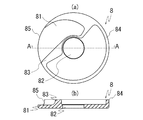
図2は図1に示した実施の形態における整流部材8を示す図であり、(a)は整流部材8の平面図、(b)は(a)に示した整流部材8のA−A面の縦断面図である。
2A and 2B are diagrams showing the rectifying
前記整流部材8は、底面に位置する底壁81、前記回転軸6を挿通する挿通孔82、前記挿通孔82の外周に沿い前記底壁81の2点間を結ぶように立設された仕切壁83、および前記底壁81の外周に位置する外周壁84を有し、前記外周壁84の一箇所または複数個所が前記底壁81の高さを限度として他の前記外周壁84よりも低いために形成される流出口85からなる。
The rectifying
本実施例においては、前記整流部材8は前記流出口85が一箇所しか形成されていないが、前記ロータ72の回転方向と同一の方向となる様に流れを調整可能とした流出口を複数形成しても良い。
In the present embodiment, the rectifying
図3は図1に示した実施の形態における作動媒体10の流れ、および図4,5,6に示す横断面図の箇所を示す説明図である。
FIG. 3 is an explanatory diagram showing the flow of the working
この図3に示したように、前記作動媒体10は、ブラシレスモータ7が駆動すると、回転軸6を共用する回転ポンプ5が同期して作動し、吸入口21から前記回転ポンプ5の低圧部が生む負圧によってケース体1を構成するポンプカバー2内に導入され、また前記回転ポンプ5の高圧部が生む圧力によって接続口31へ圧送される。そして、前記モータケース4内部に設置され前記接続口31と接続された整流部材8によって、ロータ72の回転方向と同一の方向に流れを調整されて、流出口85から前記モータケース4内部へ導入される。
As shown in FIG. 3, when the
なお、この際、もちろん前述のように前記ロータ72の回転方向と同一の方向となる様に流れを調整可能とした流出口を整流部材8に複数形成しても良い。
At this time, as a matter of course, a plurality of outlets that can adjust the flow so as to be in the same direction as the rotation direction of the
そうすると、前記流出口85からモータケース4内部へ導入された前記作動媒体10は、前述のようにステータコア711の外周面と段差42の隙間を通過しない構造か、または通過しても作動媒体通路714を通過する流量より少量となっており、かつロータコア721の内部を通過しない構造となっているため、必然的に前記ステータコア711の前記作動媒体通路714を全量、または大半が通過する様に導かれる。
Then, the working
よって、主に前記作動媒体10は、前記作動媒体通路714にて発熱体であるコイル712と接触しつつ、熱交換を行い、その後前記モータケース4に設けられた吐出口41から流出することとなり、前記コイル712の発熱を抑えたことにより熱損失の抑制によるモータ効率の向上を図ることができる。
Therefore, the working
この際、前記作動媒体10は、前記整流部材8によって流れ方向を調整されていることで、前記ロータ72の回転方向と同一であるため、前記ロータ72の回転への影響を抑制することが可能となり、結果としてこの様に作動媒体を前記モータケース4内へ整流させて流通させることにより軸受部の摩擦や前記作動媒体から受ける圧力等の抗力による負荷を低減したことによる耐久性の向上を図ることができる。
At this time, since the flow direction of the working
前記吐出口41から流出した前記作動媒体10は、その後、例えば従来周知のランキンサイクル等の廃熱回収システム(図示せず)へと送出されることとなるが、前述のように発熱体である前記コイル712と接触しつつ熱交換していることで、前記吸入口21から導入されたときよりも加熱され温度が上昇している。
The working
この作動媒体の加熱により、前記廃熱回収システムで前記作動媒体が更に加熱される際に必要となる熱量が低減され、結果として前記廃熱回収システムの効率上昇という効果を奏することができる。 By heating the working medium, the amount of heat required when the working medium is further heated by the waste heat recovery system is reduced, and as a result, the efficiency of the waste heat recovery system can be increased.
図4は図3の説明図におけるA−A面の横断面図である。 4 is a cross-sectional view of the AA plane in the explanatory diagram of FIG.
この図4に示したように、ステータコア711の外周とモータケース4の内周面はほぼ密着状態にあり、前記ステータコア711は任意の固定手段で前記モータケース4に固定されている。
As shown in FIG. 4, the outer periphery of the
また、ロータコア721は回転軸6に対して任意の固定手段で固定されており、ロータ72は前記回転軸6と一体に回転する。
The
図5は図3の説明図におけるB−B面の横断面図である。 5 is a cross-sectional view of the BB plane in the explanatory view of FIG.
この図5に示したように、ロータコア721に対してロータカバー724(724)が軸方向の両端面を覆うように固定されており、前記ロータコア721に貫通孔723を設けても、前記貫通孔723内部に作動媒体10は通過しないため、無用な乱流の発生や気泡の発生などの不具合を回避することができる。
As shown in FIG. 5, a rotor cover 724 (724) is fixed to the
図6は図3の説明図におけるC−C面の横断面図である。 6 is a cross-sectional view of the CC plane in the explanatory view of FIG.
この図6に示したように、整流部材8でロータ72の回転方向と同一の方向に流れを調整されて流出口85からモータケース4内部に導入された作動媒体10は、前記ステータコア711の作動媒体通路714を通過するように導かれる。
As shown in FIG. 6, the working
1 ケース体、2 ポンプカバー、3 モータカバー、4 モータケース、5 回転ポンプ、6 回転軸、7 ブラシレスモータ、8 整流部材、9 制御装置、10 作動媒体、21 吸入口、31 接続口、41 吐出口、42 段差部、51 外歯車、52 内歯車、53 側板、61 ブッシュ、71 ステータ、72 ロータ、711 ステータコア、712 コイル、713 切欠部、714 作動媒体通路、721 ロータコア、722 マグネット、723 貫通孔、724 ロータカバー、81 底壁、82 挿通孔、83 仕切壁、84 外周壁、85 流出口
DESCRIPTION OF
Claims (6)
The brushless motor-integrated pump according to claim 1, 2, 3, 4, or 5, wherein the rotary pump is an internal gear pump.
Priority Applications (1)
| Application Number | Priority Date | Filing Date | Title |
|---|---|---|---|
| JP2014238215A JP6442250B2 (en) | 2014-11-25 | 2014-11-25 | Brushless motor integrated pump |
Applications Claiming Priority (1)
| Application Number | Priority Date | Filing Date | Title |
|---|---|---|---|
| JP2014238215A JP6442250B2 (en) | 2014-11-25 | 2014-11-25 | Brushless motor integrated pump |
Publications (2)
| Publication Number | Publication Date |
|---|---|
| JP2016101042A JP2016101042A (en) | 2016-05-30 |
| JP6442250B2 true JP6442250B2 (en) | 2018-12-19 |
Family
ID=56077690
Family Applications (1)
| Application Number | Title | Priority Date | Filing Date |
|---|---|---|---|
| JP2014238215A Expired - Fee Related JP6442250B2 (en) | 2014-11-25 | 2014-11-25 | Brushless motor integrated pump |
Country Status (1)
| Country | Link |
|---|---|
| JP (1) | JP6442250B2 (en) |
Families Citing this family (7)
| Publication number | Priority date | Publication date | Assignee | Title |
|---|---|---|---|---|
| CN109643934B (en) | 2016-08-09 | 2021-12-03 | 日本电产株式会社 | Drive device |
| WO2018030325A1 (en) * | 2016-08-09 | 2018-02-15 | 日本電産株式会社 | Drive device |
| DE112017004001T5 (en) | 2016-08-09 | 2019-04-18 | Nidec Corporation | driving device |
| JPWO2018030325A1 (en) | 2016-08-09 | 2019-06-13 | 日本電産株式会社 | Drive unit |
| DE112017004041B4 (en) | 2016-08-09 | 2021-09-16 | Nidec Corporation | DRIVE DEVICE |
| JP2020051256A (en) * | 2018-09-21 | 2020-04-02 | 株式会社ニッキ | Brushless motor integrated pump |
| CN110863924B (en) * | 2019-11-25 | 2022-11-22 | 成都安美科能源管理有限公司 | Heat production recovery system of cogeneration unit |
Family Cites Families (3)
| Publication number | Priority date | Publication date | Assignee | Title |
|---|---|---|---|---|
| JP3603784B2 (en) * | 2000-12-14 | 2004-12-22 | 日産自動車株式会社 | Rotating electric machine |
| JP4952180B2 (en) * | 2006-10-04 | 2012-06-13 | 株式会社デンソー | Fuel pump |
| JP2013099222A (en) * | 2011-11-07 | 2013-05-20 | Toyota Motor Corp | Rotor and rotary electric machine |
-
2014
- 2014-11-25 JP JP2014238215A patent/JP6442250B2/en not_active Expired - Fee Related
Also Published As
| Publication number | Publication date |
|---|---|
| JP2016101042A (en) | 2016-05-30 |
Similar Documents
| Publication | Publication Date | Title |
|---|---|---|
| JP6442250B2 (en) | Brushless motor integrated pump | |
| CN109997296B (en) | Method for cooling an electric machine and electric machine using such a method | |
| JP4704137B2 (en) | Electric motor cooling structure and construction machine vehicle equipped with the electric motor | |
| US9660506B2 (en) | Electric motor having a communication passage | |
| JP5908741B2 (en) | Rotating electric machine | |
| CN106481567B (en) | Electric liquid pump | |
| EP3549242B1 (en) | Electric machine provided with an enclosed cooling assembly paired to an open cooling assembly | |
| JP5880842B2 (en) | Electric oil pump device | |
| US20150214817A1 (en) | Motor having cooling function | |
| JP5483095B2 (en) | Cooling structure of rotating electric machine | |
| JP4880559B2 (en) | Cooling structure in rotating electrical machines | |
| EP2879278B1 (en) | Versatile cooling housing for an electrical motor | |
| WO2016067352A1 (en) | Dynamo-electric machine | |
| EP2724450A2 (en) | Cooling structure of rotary electric machine | |
| CN109713849B (en) | Electromechanical integrated rotating electric device | |
| JP5075879B2 (en) | Electric motor | |
| US9587638B2 (en) | Drive unit for a submersible oil pump, with a fluid passage allowing the fluid in the motor housing to be discharged to the ambient enviroment | |
| JP5832752B2 (en) | Cooling device for rotating electric machine | |
| CN105337449A (en) | Direct-current permanent-magnet brushless motor | |
| EP2924852A1 (en) | High speed electrical machine with embedded drive | |
| KR101784909B1 (en) | Apparatus for cooling submerged motor pump | |
| JP2014045586A (en) | Rotary electric machine | |
| JP2000213490A (en) | Electrically-driven water pump | |
| WO2013190790A1 (en) | Liquid circulating device | |
| JP2011259634A (en) | Rotary electric machine cooling system |
Legal Events
| Date | Code | Title | Description |
|---|---|---|---|
| A621 | Written request for application examination |
Free format text: JAPANESE INTERMEDIATE CODE: A621 Effective date: 20171121 |
|
| A977 | Report on retrieval |
Free format text: JAPANESE INTERMEDIATE CODE: A971007 Effective date: 20180905 |
|
| A131 | Notification of reasons for refusal |
Free format text: JAPANESE INTERMEDIATE CODE: A131 Effective date: 20180912 |
|
| A521 | Request for written amendment filed |
Free format text: JAPANESE INTERMEDIATE CODE: A523 Effective date: 20181031 |
|
| TRDD | Decision of grant or rejection written | ||
| A01 | Written decision to grant a patent or to grant a registration (utility model) |
Free format text: JAPANESE INTERMEDIATE CODE: A01 Effective date: 20181112 |
|
| A61 | First payment of annual fees (during grant procedure) |
Free format text: JAPANESE INTERMEDIATE CODE: A61 Effective date: 20181126 |
|
| R150 | Certificate of patent or registration of utility model |
Ref document number: 6442250 Country of ref document: JP Free format text: JAPANESE INTERMEDIATE CODE: R150 |
|
| R250 | Receipt of annual fees |
Free format text: JAPANESE INTERMEDIATE CODE: R250 |
|
| LAPS | Cancellation because of no payment of annual fees |