EP1215704A2 - Fernsehglastrichter - Google Patents
Fernsehglastrichter Download PDFInfo
- Publication number
- EP1215704A2 EP1215704A2 EP01127778A EP01127778A EP1215704A2 EP 1215704 A2 EP1215704 A2 EP 1215704A2 EP 01127778 A EP01127778 A EP 01127778A EP 01127778 A EP01127778 A EP 01127778A EP 1215704 A2 EP1215704 A2 EP 1215704A2
- Authority
- EP
- European Patent Office
- Prior art keywords
- glass funnel
- funnel
- television
- along
- television glass
- Prior art date
- Legal status (The legal status is an assumption and is not a legal conclusion. Google has not performed a legal analysis and makes no representation as to the accuracy of the status listed.)
- Withdrawn
Links
Images


Classifications
-
- H—ELECTRICITY
- H01—ELECTRIC ELEMENTS
- H01J—ELECTRIC DISCHARGE TUBES OR DISCHARGE LAMPS
- H01J29/00—Details of cathode-ray tubes or of electron-beam tubes of the types covered by group H01J31/00
- H01J29/86—Vessels; Containers; Vacuum locks
- H01J29/861—Vessels or containers characterised by the form or the structure thereof
Definitions
- the invention relates to a television glass funnel for a television tube.
- the the front surface facing the viewer is essentially rectangular.
- Television tubes consist of a television glass funnel that works with the evacuated space of the tube forms the screen or television screen.
- the television glass funnel itself is divided into three areas: the funnel neck, which contains the electron beam gun and is arranged cylindrically; the Parabola area around which the deflection coil for guiding the electron beam is arranged and usually a round, increasing cross-sectional area having; the funnel body, the cross-sectional area of which is continuous increases and usually from a round or oval to a rectangular Shape passes until the cross-sectional area of the screen is reached.
- Television glass funnel and screen are over contact areas, in the following soldering edges called, connected.
- Rectangle is to be understood here and below as an area that essentially describes a rectangular shape and rounded corners could be. According to the rectangular shape of the screen is too the area of the area swept by the electron beam is rectangular.
- the object of the invention is a television glass funnel for a television tube to find the one compared to the known funnels previously used shortened design, i.e. has a shallower depth.
- the Funnels should be as weight-reduced and implosion-proof as possible.
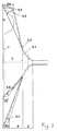
- the television glass funnel (10) shown in FIG. 2 for a television tube for soldering to a screen essentially consists of a funnel neck (1), a parabola area (2), a funnel body (8) and a soldering edge (7).
- the shape of the outer contour between the soldering edge (7) and the parabola area (2) along a section CC, which is defined by the direction of the diagonals (3.1) of the television glass funnel (10), is essentially a steeply descending straight line.
- the outer contour course between the soldering edge (7) and the parabola area (2) along the section BB, which is defined by the direction of the small axis (3.3) of the television glass funnel (10), is also essentially a steeply descending straight line.
- the shape of the outer contour between the soldering edge (7) and the parabola area (2) along a section AA, which is defined by the direction of the major axis (3.2) of the television glass funnel (10), is essentially a flat slope; in the area of the soldering edge (7) the straight line falls steeply in an arc.
- the arc of the straight line in the area of the soldering edge (7) is less along the small axis (3.3) and the least pronounced along the diagonal (3.1).
- the steepness of the respective outer contour is or the slope of the respective straight line as follows:
- the wall thicknesses (4.1, 4.2) are essentially along the diagonal (3.1) thicker than the wall thicknesses (4.3, 4.4) in the area (3.5) along the large Axis (3.2).
- the wall thicknesses (4.5, 4.6) are essentially along the small axis (3.3) thicker than along the major axis (3.2), the wall thickness (4.7) in Area (3.4) between about 1/4 of the height to 1/2 height above the soldering edge (7) is thinner than the wall thicknesses (4.5, 4.6).
- the height is measured between Solder edge (7) and start of the parabolic area (2) (height of the funnel body (8th)).
- the wall thickness in the area of the soldering edge (7) is greater than the wall thickness in Area of the funnel body (8).
- Thinner or thicker refers to the average wall thicknesses in the entire funnel body (8).
- the described distribution of the wall thicknesses means that the maximum permissible stresses are not exceeded.
- the thinner large axis (3.2) together with the thicker two other axes (3.1, 3.3) reduces the stresses in the parabolic area (2).
- the thin area (3.4) in the small axis (3.3) leads to a reduction in stress, particularly in the area of the soldered edges.
- FIG. 3 shows the maximum distance H between the respective outer contour and the respective direct connecting line between the outer edge of the soldering edge (6.3) and the outer transition (6.2) from the funnel body (8) to the parabolic area (2).
- the distance H is measured perpendicular to the straight line.
- the height of the intersection between the vertical and the outer contour above the soldering edge (7) is marked with Z (for the diagonal with Z D , for the small axis with Z K and for the large axis with Z G )
- the ratio of the height of the funnel body (8) Z to the height of the respective maximum distance H serves to describe the curvature of the outer contour (Z / Z D , Z / Z K , Z / Z G ). If the ratio is large, the axis is strongly curved.
- the curvature is Z / Z D > 2.5.
- the ratio between the maximum distance H gr (6.5) to the outer contour along the major axis (3.2) and the direct connecting line between the outer edge of the soldering edge and the outer transition from the funnel body (8) to the parabolic area (2) and the diagonal dimension (D) D / H gr ⁇ 25 and the curvature is Z / Z G > 1.6.
- the parabola area (2) in at least one section between the connection points a rectangular to the funnel neck (1) and to the funnel body (8) Cross section on.
- the outer glass contour on the small and large axis gets closer brought to the funnel center axis.
- the length of the area with rectangular Cross-section moves in the centimeter range. Because the electron beam deflection unit sits directly on the outer contour of the glass also brought the deflection unit closer to the electron beam that is inside of the funnel runs.
- the magnetic field leading through the deflection unit of the electron beam has to be built, therefore, a smaller distance overcome and may be less strong. This creates electrical energy saved.
- the television glass funnel (10) is preferably soldered to a screen, which has a shortened circumferential web.
- the diagonal (3.1) of the Funnel (10) is extended accordingly for a given screen format.
- the soldering edge (7) is placed at a height that a flatter screen with a shortened surrounding web. This increases the funnel (10) accordingly.
- the overall tube depth remains unchanged.
- the funnel shape can thus be in a good transition from the flatter extending axes (3.1 and 3.2) towards the soldering edge (7).
- the ratio of the horizontal (large) to the vertical (small) axis of the The screen preferably forms the 16: 9 format.
- the deflection angle of the electron beam along the diagonal (3.1) of the TV glass funnel (10) is preferably about 120 °. Due to the large deflection angle results in a very flat funnel, i.e. a funnel with a shortened design. However, the funnel design will be the same as before known funnels, there are impermissibly high tensions, as demonstrated by finite element calculations. So that leaves not create an implosion-proof tube.
- the dividing line between the screen and the funnel is shifted so that a shorter one Screen can be used.
Landscapes
- Vessels, Lead-In Wires, Accessory Apparatuses For Cathode-Ray Tubes (AREA)
- Joining Of Glass To Other Materials (AREA)
Abstract
Description
Vorteilhafte Weiterbildungen sind Gegenstand der Unteransprüche.
- Figur 1
- zeigt einen Fernsehglastrichter in Draufsicht mit den jeweiligen Schnitten A-A, B-B und C-C sowie der Länge D der Trichterdiagonalen.
- Figur 2
- zeigt einen Fernsehglastrichter in Seitenansicht mit den jeweiligen Schnitten.
- Figur 3
- zeigt den Fernsehglastrichter nach Figur 2 mit den jeweils maximalen Abstand H zwischen der jeweiligen Außenkontur und der jeweiligen direkten Verbindungsgeraden zwischen Lötrandaußenkante und äußerem Übergang vom Trichterkörper zum Parabelbereich.
Der Außenkonturverlauf zwischen Lötkante (7) und Parabelbereich (2) entlang des Schnittes B-B, der durch die Richtung der kleinen Achse (3.3) des Fernsehglastrichters (10) definiert ist, ist ebenfalls im wesentlichen eine steil abfallende Gerade.
Der Außenkonturverlauf zwischen Lötkante (7) und Parabelbereich (2) entlang eines Schnittes A-A, der durch die Richtung der großen Achse (3.2) des Fernsehglastrichters (10) definiert ist, ist im wesentlichen eine flach abfallende Gerade; im Bereich der Lötkante (7) fällt die Gerade bogenförmig steil ab.
Der bogenförmige Abfall der Geraden im Bereich der Lötkante (7) ist entlang der kleinen Achse (3.3) geringer und entlang der Diagonalen (3.1) am geringsten ausgeprägt.
Die beschriebene Verteilung der Wandstärken führt dazu, das die maximal zulässigen Spannungen nicht überschritten werden. Die dünnere große Achse (3.2) zusammen mit den dickeren beiden anderen Achsen (3.1, 3.3) reduziert die Spannungen im Parabelbereich (2). Der dünne Bereich (3.4) in der kleinen Achse (3.3) führt zur Reduzierung der Spannungen insbesondere im Lötkantenbereich.
| Position | 4.1 | 4.2 | 4.3 | 4.4 | 4.5 | 4.6 | 4.7 |
| Dicke [mm] | 10 | 12 | 5 | 7 | 8 | 10 | 5 |
D / Hdia = 810/20 = 40,5
für die 52 mm bei der großen Achse:
D / Hgr = 810 / 52 = 15,6
und für die 16 mm bei der kleinen Achse:
D/ Hkl = 810 / 16 = .50,6
D / Hdia = 810 / 51=15,8
D / Hgr = 810/56=14,46
D / Hkl = 810/41 = 19,75
Z / ZD = 3,3
Z / ZG = 1,85
Z / ZK = 3,47
Z / ZD = 2,1
Z / ZG = 1,65
Z / ZK = 3,47
Claims (8)
- Fernsehglastrichter (10) für eine Fernsehröhre mit1.1 einer Lötkante (7),1.2 einem Trichterhals (1),1.3 einem Parabelbereich (2) und1.4 einem Trichterkörper (8),
dadurch gekennzeichnet, dass1.5 der Außenkonturverlauf zwischen Lötkante (7) und Parabelbereich (2) entlang eines Schnittes C-C, der durch die Richtung der Diagonalen (3.1) des Fernsehglastrichters (10) definiert ist, im wesentlichen eine steil abfallende Gerade ist,1.6 entlang eines Schnittes A-A, der durch die Richtung der großen Achse (3.2) des Fernsehglastrichters (10) definiert ist, im wesentlichen eine flach abfallende Gerade ist, die im Bereich der Lötkante (7) bogenförmig steil abfällt, und1.7 entlang des Schnittes B-B, der durch die Richtung der kleinen Achse (3.3) des Fernsehglastrichters (10) definiert ist, im wesentlichen eine steil abfallende Gerade ist. - Fernsehglastrichter nach Anspruch 1,
dadurch gekennzeichnet, dass die Steilheit der jeweiligen Geraden wie folgt ist:
Steilheit kleine Achse (3.3) > > Steilheit Diagonale (3.1) > Steilheit große Achse (3.2). - Fernsehglastrichter nach Anspruch 1 oder 2,
dadurch gekennzeichnet, dass entlang der Diagonalen (3.1) die Wandstärken (4.1, 4.2) im wesentlichen dicker sind als die Wandstärken (4.3) im Bereich (3.5) entlang der großen Achse (3.2), - Fernsehglastrichter nach Anspruch 3,
dadurch gekennzeichnet,
und dass entlang der kleinen Achse (3.3 ) die Wandstärken (4.5, 4.6) im wesentlicher dicker sind als entlang der großen Achse (3.2), wobei die Wandstärke (4.7) im Bereich (3.4) zwischen etwa 1/4 der Höhe bis 1/2 Höhe oberhalb der Lötkante (11) dünner ist als die Wandstärken (4.5, 4.6). - Fernsehglastrichter nach wenigstens einem der Ansprüche 1 bis 4,
dadurch gekennzeichnet, dass die Krümmung der Außenkontur wie folgt ist:
für die Diagonale Z / ZD > 2,5,
für die große Achse Z / ZG > 1,6 und
für die kleine Achse Z / ZK > 2,6. - Fernsehglastrichter nach wenigstens einem der Ansprüche 1 bis 5,
dadurch gekennzeichnet, dass
das Verhältnis zwischen den jeweils maximalen Abstand H (6.4, 6.5, 6.6) zur jeweiligen Außenkontur (3.1, 3.2, 3.3) und der jeweiligen direkten Verbindungsgerade zwischen Lötrandaußenkante (6.3) und äußerem Übergang (6.2) vom Trichterkörper (8) zum Parabelbereich (2) und dem Diagonalmaß (D) wie folgt ist:
in Richtung der Diagonalen (3.1) D / Hdia > 28,
in Richtung der großen Achse (3.2) D / Hgr < 25 und
in Richtung der kleinen Achse (3.3) D / Hkl > 33. - Fernsehglastrichter nach wenigstens einem der Ansprüche 1 bis 6,
dadurch gekennzeichnet, dass
dass der Parabelbereich (2) in mindestens einem Teilabschnitt zwischen den Anschlussstellen zum Trichterhals (1) und zum Trichterkörper (8) einen rechteckigen Querschnitt aufweist. - Fernsehglastrichter nach wenigstens einem der Ansprüche 1 bis 7,
dadurch gekennzeichnet, dass
der Fernsehglastrichter (10) mit einem Bildschirm verlötet ist, wobei der Bildschirm einen verkürzten Steg aufweist und die Höhe des Fernsehglastrichters (10) entsprechend verlängert ist.
Applications Claiming Priority (2)
| Application Number | Priority Date | Filing Date | Title |
|---|---|---|---|
| DE10063034A DE10063034B4 (de) | 2000-12-18 | 2000-12-18 | Fernsehglastrichter |
| DE10063034 | 2000-12-18 |
Publications (2)
| Publication Number | Publication Date |
|---|---|
| EP1215704A2 true EP1215704A2 (de) | 2002-06-19 |
| EP1215704A3 EP1215704A3 (de) | 2004-12-01 |
Family
ID=7667622
Family Applications (1)
| Application Number | Title | Priority Date | Filing Date |
|---|---|---|---|
| EP01127778A Withdrawn EP1215704A3 (de) | 2000-12-18 | 2001-11-22 | Fernsehglastrichter |
Country Status (4)
| Country | Link |
|---|---|
| US (1) | US6680566B2 (de) |
| EP (1) | EP1215704A3 (de) |
| JP (1) | JP3683847B2 (de) |
| DE (1) | DE10063034B4 (de) |
Families Citing this family (5)
| Publication number | Priority date | Publication date | Assignee | Title |
|---|---|---|---|---|
| KR100396624B1 (ko) * | 2001-09-14 | 2003-09-02 | 엘지.필립스디스플레이(주) | 음극선관용 펀넬 구조 |
| AU2003303402A1 (en) * | 2002-12-30 | 2004-07-22 | Lg. Philips Dislays | Cathode ray tube with a conical portion |
| CN1322536C (zh) * | 2004-02-10 | 2007-06-20 | 松下东芝映象显示株式会社 | 阴极射线管装置 |
| KR100612314B1 (ko) * | 2004-12-03 | 2006-08-11 | 삼성에스디아이 주식회사 | 음극선관 |
| KR100712904B1 (ko) * | 2004-12-28 | 2007-05-02 | 엘지.필립스 디스플레이 주식회사 | 음극선관 |
Family Cites Families (4)
| Publication number | Priority date | Publication date | Assignee | Title |
|---|---|---|---|---|
| DE2407527B2 (de) * | 1974-02-16 | 1976-01-08 | Jenaer Glaswerk Schott & Gen., 6500 Mainz | Elektronenstrahlröhrenkolben mit rechteckigem Bildschirm |
| US4788471A (en) | 1986-11-21 | 1988-11-29 | Zenith Electronics Corporation | Sealing for CRT components |
| US5751103A (en) * | 1996-08-13 | 1998-05-12 | Thomson Consumer Electronics, Inc. | Color picture tube having improved funnel |
| DE10025780C2 (de) * | 2000-05-26 | 2002-10-24 | Schott Glas | Herstellungsoptimierter und gewichtsreduzierter Glastrichter für eine Fernsehbildröhre |
-
2000
- 2000-12-18 DE DE10063034A patent/DE10063034B4/de not_active Expired - Fee Related
-
2001
- 2001-11-15 JP JP2001349913A patent/JP3683847B2/ja not_active Expired - Fee Related
- 2001-11-22 EP EP01127778A patent/EP1215704A3/de not_active Withdrawn
- 2001-12-17 US US10/023,462 patent/US6680566B2/en not_active Expired - Fee Related
Also Published As
| Publication number | Publication date |
|---|---|
| US20020153823A1 (en) | 2002-10-24 |
| DE10063034A1 (de) | 2002-07-04 |
| US6680566B2 (en) | 2004-01-20 |
| DE10063034B4 (de) | 2005-11-24 |
| EP1215704A3 (de) | 2004-12-01 |
| JP3683847B2 (ja) | 2005-08-17 |
| JP2002216673A (ja) | 2002-08-02 |
Similar Documents
| Publication | Publication Date | Title |
|---|---|---|
| DE69400361T2 (de) | Farbkathodenstrahlröhre | |
| DE4023528A1 (de) | Breitbandantenne an einem kraftfahrzeug-heckfensterglas | |
| DE4109855A1 (de) | Kathodenstrahlroehre mit verbessertem schirmtraeger mit einem seitenverhaeltnis von 16 x 9 | |
| DE2039504C3 (de) | Glaskolben für eine Weitwinkel- Fernsehbildröhre | |
| DE69812274T2 (de) | Kathodenstrahlröhre | |
| DD232575A5 (de) | Kathodenstrahlroehre mit einer eine im wesentlichen ebene bildschirmperipherie aufweisenden frontplatte | |
| DE10063034B4 (de) | Fernsehglastrichter | |
| DE69513906T2 (de) | Ablenkjoch und Ablenkjoch enthaltende Farbkathodenstrahlröhre | |
| DE69919470T2 (de) | Bildanzeigegerät mit einem kegelförmigen teil | |
| DE10031515A1 (de) | Glastrichter für eine Kathodenstrahlröhre und eine Kathodenstrahlröhre | |
| DE69301871T2 (de) | Kathodenstrahlröhre mit einer inneren magnetischen Abschirmung mit Verfestigungsrippen | |
| DE202025101203U1 (de) | Solarzelle und Solarmodul | |
| DE69602162T2 (de) | Kathodenstruktur mit einem heizelement | |
| DE69535536T2 (de) | Ablenkjoch und mit dem Ablenkjoch versehene Farbkathodenstrahlröhre | |
| DE2738173A1 (de) | Ablenkjochsystem fuer farbfernsehempfaenger | |
| DE3002679A1 (de) | Farbkathodenstrahlroehre | |
| DE3105698A1 (de) | Vakuumgehaeuse | |
| DE69302128T2 (de) | Farbbildröhre mit innerer magnetischer Abschirmung | |
| DE10228679B4 (de) | Trichter für Kathodenstrahlröhren | |
| EP0432217B1 (de) | In-line-farbbildröhre | |
| DE19922225C1 (de) | Fernsehtrichter mit abschnittsweise rechteckiger Parabel | |
| DE2407527A1 (de) | Rechteckige elektronenstrahlroehre erhoehter festigkeit | |
| DE3783641T2 (de) | Elektronenlinsensystem fuer die ablenkverstaerkung in einer kathodenstrahlroehre. | |
| DE3216039A1 (de) | Elektronenstrahl-erzeugungssystem sowie kathodenstrahlroehre und fernsehempfaenger mit einem solchen system | |
| DE4137504A1 (de) | Farbkathodenstrahlroehre |
Legal Events
| Date | Code | Title | Description |
|---|---|---|---|
| PUAI | Public reference made under article 153(3) epc to a published international application that has entered the european phase |
Free format text: ORIGINAL CODE: 0009012 |
|
| 17P | Request for examination filed |
Effective date: 20011122 |
|
| AK | Designated contracting states |
Kind code of ref document: A2 Designated state(s): AT BE CH CY DE DK ES FI FR GB GR IE IT LI LU MC NL PT SE TR |
|
| AX | Request for extension of the european patent |
Free format text: AL;LT;LV;MK;RO;SI |
|
| RAP1 | Party data changed (applicant data changed or rights of an application transferred) |
Owner name: SCHOTT AG |
|
| PUAL | Search report despatched |
Free format text: ORIGINAL CODE: 0009013 |
|
| AK | Designated contracting states |
Kind code of ref document: A3 Designated state(s): AT BE CH CY DE DK ES FI FR GB GR IE IT LI LU MC NL PT SE TR |
|
| AX | Request for extension of the european patent |
Extension state: AL LT LV MK RO SI |
|
| AKX | Designation fees paid |
Designated state(s): AT BE CH CY DE DK ES FI FR GB GR IE IT LI LU MC NL PT SE TR |
|
| STAA | Information on the status of an ep patent application or granted ep patent |
Free format text: STATUS: THE APPLICATION HAS BEEN WITHDRAWN |
|
| 18W | Application withdrawn |
Effective date: 20060420 |
|
| REG | Reference to a national code |
Ref country code: HK Ref legal event code: WD Ref document number: 1049231 Country of ref document: HK |