EP1214758B1 - Method and apparatus for spectral shaping of an optical pulse - Google Patents
Method and apparatus for spectral shaping of an optical pulse Download PDFInfo
- Publication number
- EP1214758B1 EP1214758B1 EP00911604A EP00911604A EP1214758B1 EP 1214758 B1 EP1214758 B1 EP 1214758B1 EP 00911604 A EP00911604 A EP 00911604A EP 00911604 A EP00911604 A EP 00911604A EP 1214758 B1 EP1214758 B1 EP 1214758B1
- Authority
- EP
- European Patent Office
- Prior art keywords
- optical
- pulse
- grating
- chromatically dispersed
- dispersed output
- Prior art date
- Legal status (The legal status is an assumption and is not a legal conclusion. Google has not performed a legal analysis and makes no representation as to the accuracy of the status listed.)
- Expired - Lifetime
Links
- 230000003287 optical effect Effects 0.000 title claims description 62
- 238000000034 method Methods 0.000 title claims description 36
- 238000007493 shaping process Methods 0.000 title claims description 24
- 230000003595 spectral effect Effects 0.000 title claims description 24
- 238000001228 spectrum Methods 0.000 claims description 36
- 239000000835 fiber Substances 0.000 claims description 24
- 239000013307 optical fiber Substances 0.000 claims description 19
- 239000006185 dispersion Substances 0.000 claims description 14
- 238000012014 optical coherence tomography Methods 0.000 claims description 10
- 230000002123 temporal effect Effects 0.000 claims description 9
- 238000004891 communication Methods 0.000 claims description 8
- 230000003247 decreasing effect Effects 0.000 claims description 3
- 230000008569 process Effects 0.000 claims description 2
- 230000001902 propagating effect Effects 0.000 claims description 2
- 230000008878 coupling Effects 0.000 claims 1
- 238000010168 coupling process Methods 0.000 claims 1
- 238000005859 coupling reaction Methods 0.000 claims 1
- 230000005855 radiation Effects 0.000 description 4
- 230000001427 coherent effect Effects 0.000 description 2
- 238000012937 correction Methods 0.000 description 2
- 230000001419 dependent effect Effects 0.000 description 2
- 238000010586 diagram Methods 0.000 description 2
- 230000003134 recirculating effect Effects 0.000 description 2
- 229910052691 Erbium Inorganic materials 0.000 description 1
- VYPSYNLAJGMNEJ-UHFFFAOYSA-N Silicium dioxide Chemical compound O=[Si]=O VYPSYNLAJGMNEJ-UHFFFAOYSA-N 0.000 description 1
- 230000002238 attenuated effect Effects 0.000 description 1
- 230000008901 benefit Effects 0.000 description 1
- 230000005540 biological transmission Effects 0.000 description 1
- 238000004140 cleaning Methods 0.000 description 1
- 230000006835 compression Effects 0.000 description 1
- 238000007906 compression Methods 0.000 description 1
- 230000002596 correlated effect Effects 0.000 description 1
- 230000000875 corresponding effect Effects 0.000 description 1
- 230000003111 delayed effect Effects 0.000 description 1
- 230000000694 effects Effects 0.000 description 1
- UYAHIZSMUZPPFV-UHFFFAOYSA-N erbium Chemical compound [Er] UYAHIZSMUZPPFV-UHFFFAOYSA-N 0.000 description 1
- 238000002474 experimental method Methods 0.000 description 1
- 230000001788 irregular Effects 0.000 description 1
- GQYHUHYESMUTHG-UHFFFAOYSA-N lithium niobate Chemical compound [Li+].[O-][Nb](=O)=O GQYHUHYESMUTHG-UHFFFAOYSA-N 0.000 description 1
- 238000005259 measurement Methods 0.000 description 1
- 238000012986 modification Methods 0.000 description 1
- 230000004048 modification Effects 0.000 description 1
- 230000010287 polarization Effects 0.000 description 1
- 230000000135 prohibitive effect Effects 0.000 description 1
- 230000000644 propagated effect Effects 0.000 description 1
- 230000009467 reduction Effects 0.000 description 1
Images


Classifications
-
- G—PHYSICS
- G02—OPTICS
- G02B—OPTICAL ELEMENTS, SYSTEMS OR APPARATUS
- G02B6/00—Light guides; Structural details of arrangements comprising light guides and other optical elements, e.g. couplings
- G02B6/02—Optical fibres with cladding with or without a coating
- G02B6/02057—Optical fibres with cladding with or without a coating comprising gratings
- G02B6/02076—Refractive index modulation gratings, e.g. Bragg gratings
- G02B6/02123—Refractive index modulation gratings, e.g. Bragg gratings characterised by the method of manufacture of the grating
- G02B6/02133—Refractive index modulation gratings, e.g. Bragg gratings characterised by the method of manufacture of the grating using beam interference
- G02B6/02138—Refractive index modulation gratings, e.g. Bragg gratings characterised by the method of manufacture of the grating using beam interference based on illuminating a phase mask
-
- G—PHYSICS
- G02—OPTICS
- G02B—OPTICAL ELEMENTS, SYSTEMS OR APPARATUS
- G02B6/00—Light guides; Structural details of arrangements comprising light guides and other optical elements, e.g. couplings
- G02B6/02—Optical fibres with cladding with or without a coating
- G02B6/02057—Optical fibres with cladding with or without a coating comprising gratings
- G02B6/02076—Refractive index modulation gratings, e.g. Bragg gratings
- G02B6/02123—Refractive index modulation gratings, e.g. Bragg gratings characterised by the method of manufacture of the grating
- G02B6/02147—Point by point fabrication, i.e. grating elements induced one step at a time along the fibre, e.g. by scanning a laser beam, arc discharge scanning
-
- G—PHYSICS
- G02—OPTICS
- G02B—OPTICAL ELEMENTS, SYSTEMS OR APPARATUS
- G02B6/00—Light guides; Structural details of arrangements comprising light guides and other optical elements, e.g. couplings
- G02B6/10—Light guides; Structural details of arrangements comprising light guides and other optical elements, e.g. couplings of the optical waveguide type
- G02B6/12—Light guides; Structural details of arrangements comprising light guides and other optical elements, e.g. couplings of the optical waveguide type of the integrated circuit kind
- G02B6/122—Basic optical elements, e.g. light-guiding paths
- G02B6/124—Geodesic lenses or integrated gratings
-
- G—PHYSICS
- G02—OPTICS
- G02B—OPTICAL ELEMENTS, SYSTEMS OR APPARATUS
- G02B6/00—Light guides; Structural details of arrangements comprising light guides and other optical elements, e.g. couplings
- G02B6/24—Coupling light guides
- G02B6/26—Optical coupling means
- G02B6/28—Optical coupling means having data bus means, i.e. plural waveguides interconnected and providing an inherently bidirectional system by mixing and splitting signals
- G02B6/293—Optical coupling means having data bus means, i.e. plural waveguides interconnected and providing an inherently bidirectional system by mixing and splitting signals with wavelength selective means
- G02B6/29304—Optical coupling means having data bus means, i.e. plural waveguides interconnected and providing an inherently bidirectional system by mixing and splitting signals with wavelength selective means operating by diffraction, e.g. grating
- G02B6/29316—Light guides comprising a diffractive element, e.g. grating in or on the light guide such that diffracted light is confined in the light guide
- G02B6/29317—Light guides of the optical fibre type
-
- G—PHYSICS
- G02—OPTICS
- G02F—OPTICAL DEVICES OR ARRANGEMENTS FOR THE CONTROL OF LIGHT BY MODIFICATION OF THE OPTICAL PROPERTIES OF THE MEDIA OF THE ELEMENTS INVOLVED THEREIN; NON-LINEAR OPTICS; FREQUENCY-CHANGING OF LIGHT; OPTICAL LOGIC ELEMENTS; OPTICAL ANALOGUE/DIGITAL CONVERTERS
- G02F1/00—Devices or arrangements for the control of the intensity, colour, phase, polarisation or direction of light arriving from an independent light source, e.g. switching, gating or modulating; Non-linear optics
- G02F1/01—Devices or arrangements for the control of the intensity, colour, phase, polarisation or direction of light arriving from an independent light source, e.g. switching, gating or modulating; Non-linear optics for the control of the intensity, phase, polarisation or colour
- G02F1/03—Devices or arrangements for the control of the intensity, colour, phase, polarisation or direction of light arriving from an independent light source, e.g. switching, gating or modulating; Non-linear optics for the control of the intensity, phase, polarisation or colour based on ceramics or electro-optical crystals, e.g. exhibiting Pockels effect or Kerr effect
-
- H—ELECTRICITY
- H01—ELECTRIC ELEMENTS
- H01S—DEVICES USING THE PROCESS OF LIGHT AMPLIFICATION BY STIMULATED EMISSION OF RADIATION [LASER] TO AMPLIFY OR GENERATE LIGHT; DEVICES USING STIMULATED EMISSION OF ELECTROMAGNETIC RADIATION IN WAVE RANGES OTHER THAN OPTICAL
- H01S3/00—Lasers, i.e. devices using stimulated emission of electromagnetic radiation in the infrared, visible or ultraviolet wave range
- H01S3/005—Optical devices external to the laser cavity, specially adapted for lasers, e.g. for homogenisation of the beam or for manipulating laser pulses, e.g. pulse shaping
- H01S3/0057—Temporal shaping, e.g. pulse compression, frequency chirping
-
- G—PHYSICS
- G02—OPTICS
- G02B—OPTICAL ELEMENTS, SYSTEMS OR APPARATUS
- G02B6/00—Light guides; Structural details of arrangements comprising light guides and other optical elements, e.g. couplings
- G02B6/10—Light guides; Structural details of arrangements comprising light guides and other optical elements, e.g. couplings of the optical waveguide type
- G02B6/12—Light guides; Structural details of arrangements comprising light guides and other optical elements, e.g. couplings of the optical waveguide type of the integrated circuit kind
- G02B2006/12083—Constructional arrangements
- G02B2006/12107—Grating
-
- G—PHYSICS
- G02—OPTICS
- G02B—OPTICAL ELEMENTS, SYSTEMS OR APPARATUS
- G02B6/00—Light guides; Structural details of arrangements comprising light guides and other optical elements, e.g. couplings
- G02B6/10—Light guides; Structural details of arrangements comprising light guides and other optical elements, e.g. couplings of the optical waveguide type
- G02B6/12—Light guides; Structural details of arrangements comprising light guides and other optical elements, e.g. couplings of the optical waveguide type of the integrated circuit kind
- G02B2006/12083—Constructional arrangements
- G02B2006/12109—Filter
-
- G—PHYSICS
- G02—OPTICS
- G02B—OPTICAL ELEMENTS, SYSTEMS OR APPARATUS
- G02B6/00—Light guides; Structural details of arrangements comprising light guides and other optical elements, e.g. couplings
- G02B6/10—Light guides; Structural details of arrangements comprising light guides and other optical elements, e.g. couplings of the optical waveguide type
- G02B6/12—Light guides; Structural details of arrangements comprising light guides and other optical elements, e.g. couplings of the optical waveguide type of the integrated circuit kind
- G02B2006/12133—Functions
- G02B2006/12138—Sensor
-
- G—PHYSICS
- G02—OPTICS
- G02B—OPTICAL ELEMENTS, SYSTEMS OR APPARATUS
- G02B6/00—Light guides; Structural details of arrangements comprising light guides and other optical elements, e.g. couplings
- G02B6/02—Optical fibres with cladding with or without a coating
- G02B6/02057—Optical fibres with cladding with or without a coating comprising gratings
- G02B6/02076—Refractive index modulation gratings, e.g. Bragg gratings
- G02B6/0208—Refractive index modulation gratings, e.g. Bragg gratings characterised by their structure, wavelength response
- G02B6/02085—Refractive index modulation gratings, e.g. Bragg gratings characterised by their structure, wavelength response characterised by the grating profile, e.g. chirped, apodised, tilted, helical
- G02B6/02095—Long period gratings, i.e. transmission gratings coupling light between core and cladding modes
-
- G—PHYSICS
- G02—OPTICS
- G02B—OPTICAL ELEMENTS, SYSTEMS OR APPARATUS
- G02B6/00—Light guides; Structural details of arrangements comprising light guides and other optical elements, e.g. couplings
- G02B6/02—Optical fibres with cladding with or without a coating
- G02B6/02057—Optical fibres with cladding with or without a coating comprising gratings
- G02B6/02076—Refractive index modulation gratings, e.g. Bragg gratings
- G02B6/02123—Refractive index modulation gratings, e.g. Bragg gratings characterised by the method of manufacture of the grating
- G02B6/02152—Refractive index modulation gratings, e.g. Bragg gratings characterised by the method of manufacture of the grating involving moving the fibre or a manufacturing element, stretching of the fibre
-
- G—PHYSICS
- G02—OPTICS
- G02B—OPTICAL ELEMENTS, SYSTEMS OR APPARATUS
- G02B6/00—Light guides; Structural details of arrangements comprising light guides and other optical elements, e.g. couplings
- G02B6/24—Coupling light guides
- G02B6/26—Optical coupling means
- G02B6/27—Optical coupling means with polarisation selective and adjusting means
- G02B6/2726—Optical coupling means with polarisation selective and adjusting means in or on light guides, e.g. polarisation means assembled in a light guide
- G02B6/274—Optical coupling means with polarisation selective and adjusting means in or on light guides, e.g. polarisation means assembled in a light guide based on light guide birefringence, e.g. due to coupling between light guides
-
- G—PHYSICS
- G02—OPTICS
- G02B—OPTICAL ELEMENTS, SYSTEMS OR APPARATUS
- G02B6/00—Light guides; Structural details of arrangements comprising light guides and other optical elements, e.g. couplings
- G02B6/24—Coupling light guides
- G02B6/26—Optical coupling means
- G02B6/28—Optical coupling means having data bus means, i.e. plural waveguides interconnected and providing an inherently bidirectional system by mixing and splitting signals
- G02B6/293—Optical coupling means having data bus means, i.e. plural waveguides interconnected and providing an inherently bidirectional system by mixing and splitting signals with wavelength selective means
- G02B6/29379—Optical coupling means having data bus means, i.e. plural waveguides interconnected and providing an inherently bidirectional system by mixing and splitting signals with wavelength selective means characterised by the function or use of the complete device
- G02B6/29392—Controlling dispersion
- G02B6/29394—Compensating wavelength dispersion
-
- G—PHYSICS
- G02—OPTICS
- G02F—OPTICAL DEVICES OR ARRANGEMENTS FOR THE CONTROL OF LIGHT BY MODIFICATION OF THE OPTICAL PROPERTIES OF THE MEDIA OF THE ELEMENTS INVOLVED THEREIN; NON-LINEAR OPTICS; FREQUENCY-CHANGING OF LIGHT; OPTICAL LOGIC ELEMENTS; OPTICAL ANALOGUE/DIGITAL CONVERTERS
- G02F2202/00—Materials and properties
- G02F2202/20—LiNbO3, LiTaO3
-
- G—PHYSICS
- G02—OPTICS
- G02F—OPTICAL DEVICES OR ARRANGEMENTS FOR THE CONTROL OF LIGHT BY MODIFICATION OF THE OPTICAL PROPERTIES OF THE MEDIA OF THE ELEMENTS INVOLVED THEREIN; NON-LINEAR OPTICS; FREQUENCY-CHANGING OF LIGHT; OPTICAL LOGIC ELEMENTS; OPTICAL ANALOGUE/DIGITAL CONVERTERS
- G02F2203/00—Function characteristic
- G02F2203/26—Pulse shaping; Apparatus or methods therefor
Definitions
- the present invention relates to a method and apparatus for stretching and shaping the spectrum of an optical pulse. More specifically, the present invention provides a commercially feasible method and apparatus for arbitrarily shaping the spectrum of an optical pulse by first stretching it with a novel long length fiber Bragg grating and then modifying the amplitude of the stretched pulse temporally.
- An optical pulse is a brief burst of radiation in the optical wavelength range.
- an unchirped pulse of duration t has a spectral width of ⁇ 1/ t , e.g. a ⁇ 1 nanosecond (10 -9 second) pulse has a ⁇ 1 GHz (10 9 Hz) spectral width.
- the time limit on what constitutes a pulse depends on the application for which the pulse is being sampled or utilized.
- Various methods may be used to produce optical pulses, such as by Q-switching lasers, mode-locking lasers, or rapidly modulating a light signal.
- a pulse of a given duration has a determinable spectral width, and is thus comprised of radiation from a span of wavelengths.
- a pulse is comprised of many wavelengths of radiation, all these wavelengths will travel simultaneously generally through an optical path, possible exceptions are when the pulse is chirped and thus certain wavelengths lag behind others.
- the method of the present invention separates these different wavelengths in time so that they can be individually accessed and modified.
- optical pulses In several applications, the spectral properties of optical pulses are exploited to perform useful functions. Broad-spectrum optical sources generated by pulsed radiation are important in many applications. In some optical fiber-based communication systems, the cost of individual distributed feedback laser (DFB) sources may be prohibitive, so sources for spectrally sliced and chirped pulse Wavelength-Division Multiplexer (WDM) communication systems, where signals are sent separately over many wavelength channels, are attractive. WDM communication systems are typically added to preexisting systems when increased capacity is needed but the ability for higher speed data transmission is limited. The spectral properties of optical pulses also are critical to applications where the coherence function of the pulse is of interest, such as Optical Coherence Tomography (OCT) and Interferometric Fiber Optic Gyroscopes (IFOGs).
- OCT Optical Coherence Tomography
- IFOGs Interferometric Fiber Optic Gyroscopes
- the spectrum of a pulse should be broad, as well as smoothly varying and well controlled.
- spectral shape can be as critical as spectral width.
- WDM WDM
- OCT OCT
- IFOG IFOG
- the shape of the spectrum directly impacts performance.
- channel equalization requires a flat spectrum
- OCT image resolution is determined by the signal spectrum
- IFOG non-Gaussian spectra cause errors due to coherent Rayleigh backscattering.
- the initial spectrum of a pulse must be modified to optimize the performance of a given application, such as WDM, OCT, and IFOG.
- Time domain spectral shaping is another technique for spectral shaping, where a pulse is chromatically dispersed temporally and then the amplitude of the stretched pulse is modified.
- the amplitude of the stretched pulse in the time domain is referred to in the present text as the pulse envelope.
- the pulse envelope is generally stretched by several times its initial duration. With proper calibration and correction factors, the stretched pulse envelope can be correlated to the frequency spectrum of the pulse. Hence, altering the amplitude of the stretched pulse envelope modifies the frequency spectrum of the pulse.
- the temporal resolution of the optical modulator and electronics used to modify the stretched envelope limits the available wavelength resolution of the spectral shaping. Standard available electronic equipment has a bandwidth that is generally not greater than ⁇ 1 GHz and is thus limited to a ⁇ 1 ns temporal resolution.
- Pulse stretching has been demonstrated experimentally by using a long length of optical fiber to stretch the pulse temporally.
- a 20 km length of standard single mode fiber (SMF) with group velocity dispersion of ⁇ 15 ps/nm, was used to stretch pulses emitted from a mode-locked laser.
- SMF standard single mode fiber
- the pulse envelope was stretched from ⁇ 1 picosecond to -25 nanoseconds. Because the pulse was chromatically dispersed temporally and the initial pulse envelope was much smaller than the stretched envelope, the stretched pulse envelope was nearly identical to the spectrum shape of the pulse, with proper correction and calibration factors.
- the present invention provides a method and an apparatus for stretching an optical pulse and shaping its spectrum according to claims 1 and 9, respectively, as well as an optical coherence tomography system, an interferometric optical fiber gyroscope, and an optical fiber communication system according to claims 16 to 18, respectively, employing an apparatus of claim 9.
- the present invention comprises a method and an apparatus for stretching an optical pulse and shaping its spectrum.
- the method comprises the step of:providing a an optical fiber element having a first long length fiber Bragg grating longer than 20 cm having a refractive index pattern of varying periodicity depending on the desired direction of stretch of the optical pulse.
- the optical pulse is launched into the fiber Bragg grating, wherein the Bragg grating reflects the pulse in a chromatically dispersed output.
- the reflected output is coupled with an optical modulator programmed to temporally modify the amplitude of the chromatically dispersed output to attenuate selected optical frequencies in a desired pattern.
- the step of providing a grating includes providing a grating having a chromatic dispersion capability between ⁇ 10 ps/nm and 10 ns/nm.
- the initial light pulse may have less than 90 % of its energy in a 10 MHz spectral range.
- the step of temporally modifying the amplitude of the chromatically dispersed output may be accomplished using an arbitrary waveform generator having at least 10 MHz bandwidth.
- the chromatically dispersed output may be recompressed.
- the step of recompressing the chromatically dispersed output may be accomplished by launching the chromatically dispersed output into a fiber element having a second grating of opposite sign dispersion to that of the first grating.
- the chromatically dispersed output may be launched into an opposite end of the original optical fiber element.
- the method of the present invention further may include the step of launching the chromatically dispersed output into an optical system that relies on nonlinear optical processes.
- the present invention further includes a pulse stretching and shaping apparatus for stretching and arbitrarily shaping the spectrum of an optical pulse with a desired wavelength resolution ⁇ res .
- the apparatus includes a routing optical device and an optical fiber element having a Bragg grating.
- the routing optical device routs energy between different waveguides, and has an input port to receive the optical pulse.
- the routing optical device is a non-reciprocal optical device, such as a circulator.
- the device may be a connector that couples energy from one waveguide to another. circulator.
- the device may be a connector that couples energy from one waveguide to another.
- the optical fiber element has a long-length fiber Bragg grating longer than 20 cm such as to provide sufficient delay between the shortest and longest wavelengths in the reflection band window to exhibit the desired wavelength resolution ⁇ res and is optically coupled to the routing optical device.
- the Bragg grating has a chromatic dispersion capability between ⁇ 10 ps/nm and 10 ns/nm. And is greater than 20 cms. In length. In other embodiments, the length of the Bragg grating may further exceed two meters.
- the apparatus further includes said waveform generator and an optical amplitude modulator that temporally modifies the amplitude of the chromatically dispersed output to attenuate selected optical frequencies.
- the apparatus of the present invention is included in a variety of more complex systems, such as an optical coherence tomography system, an interferometric optical fiber gyroscope, or an optical fiber communication system.
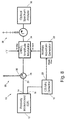
- FIG. 1 illustrates an optical pulse spectral stretcher and shaper (OPSSS) 10 in accordance with the present invention.
- OPSSS 10 is coupled to receive a pulse from a source 12, a passively modelocked stretched pulse erbium-doped fiber laser (EDFL) with a rejection output port 14 and a variable output port 16.
- the variable output port 16 is coupled to a 125 MHz detector 18 having a trigger output 20 that triggers a digitally programmable arbitrary waveform generator (AWG) 22.
- AMG digitally programmable arbitrary waveform generator
- the OPSSS 10 includes a non-reciprocal device 24 and a chirped long-length fiber Bragg grating (FBG) 26 having an index of refraction pattern of varying periodicity.
- the periodicity may be increasing or decreasing, depending on the desired direction of stretch of the optical pulse.
- the non-reciprocal device 24 comprises a circulator having an input port 28, a recirculating port 30, and an output port 32.
- the rejection output port 14 is coupled to the input port 28 and the long-length Bragg grating 26 is coupled to the recirculating port 30.
- the term long-length refers to an FBG that provide sufficient delay between the shortest and longest wavelengths in the reflection band window to exhibit a sufficient wavelength resolution.
- the resolution depends on physical parameters such as grating length L, optical bandwidth W, and the temporal resolution ⁇ 0 of available electronics.
- ⁇ res ⁇ 0 W/ ⁇ ; where ⁇ is the total delay induced by the grating, that is, the differential delay between the maximum and minimum wavelengths reflected by the FBG.
- the factor of 2 arises because the FBG is a reflective device and delayed wavelengths traverse a given length of the FBG twice.
- ⁇ 0 and ⁇ res may vary for different applications. However, no matter what the situation, a standard chirped FBG ( ⁇ 15 centimeters) is too short.
- W is the ⁇ 40 nm gain bandwidth of an erbium doped fiber amplifier (EDFA), and the highest speed commercial arbitrary waveform generator has a temporal resolution ⁇ 0 of ⁇ 1 nanosecond. Equation 2 indicates that the required length of the FBG would be ⁇ 10 meters. Even a moderate system, such as one seeking a final pulse width of ⁇ 25 ns, requires a length of ⁇ 2.4 meters.
- a standard 5-cm FBG provides a differential delay ⁇ of merely 0.5 nanoseconds.
- ⁇ res of 0.4 nm would require ⁇ 0 to be 5 picoseconds, corresponding to a bandwidth of 200 GHz.
- Such a waveform generator currently does not exist.
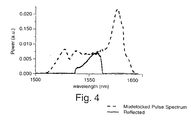
- the EDFL 12 was set to emit a broad spectrum (approximately 70 nm wide) Gaussian pulse, which was received by the circulator 24 and transmitted to a 3.86 meter long chirped FBG 26.
- Figure 2 is an autocorrelation trace of the original pulse incident on the FBG. The pulse is less than 1.5 picoseconds, too short to be measured directly with a photodetector. Only an indirect autocorrelation measurement is possible.
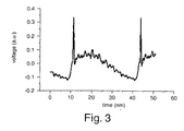
- the scope trace in Figure 3 shows the resulting stretched pulse measuring approximately 30 nanoseconds, after passage through the OPSSS 10.
- the frequency spectrum and the pulse envelope are similar, with the use of appropriate scaling factors.
- the wavelength and temporal resolutions are linked.
- the spike shown at the front of the pulse is a small reflection between the FBG 26 and the circulator 24.
- the FBG 26 reflects all wavelengths within a 28 nm window centered at 1550 nm (see Figure 3).
- the FBG 26 also provides a dispersion of -1360.8 ps/nm and thus a relative delay of ⁇ 38 ns between the shortest and longest wavelengths reflected by the FBG.
- the stretched pulse is routed by the circulator 24 to a lithium niobate amplitude modulator 34 driven by a 1GHz internal clock AWG.
- the optical spectrum is then viewed on an optical spectrum analyzer 36.
- Time domain spectral shaping may be used to perform many functions, such as the removal of pulse wings, the generation of pulses with Gaussian-shaped spectra, and the flattening of pulse spectra.
- TDSS may be comprised entirely of fiber-based components that are low-loss and robust, whereas the spatial domain spectral shaping methods are bulky and require careful alignment of light beams that are not confined by optical waveguides.
- the FBG 26 may comprise a grating made from polarization maintaining fiber.
- a modulation signal was programmed to suppress the ripples, resulting in a much smoother spectrum. An average power reduction of 4.0 dB was observed when the filter program was activated.
- the filter resolution ⁇ of the technique is dependent upon the temporal resolution of the AWG, the bandwidth and the length of the grating.
- the repetition rate of the pulse source also places a limit on the maximum possible stretching.
- Virtually any desired filter shape may be implemented using the method and apparatus of the present invention.
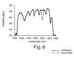
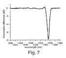
- Figures 6 and 7 illustrate the effect of a notch filter, a different kind of filter, that may be implemented using the present invention.
- the shaped and stretched signal may be recompressed using a second using a second fiber element having a Bragg grating 38 of opposite sign as that of the first grating.
- the Bragg grating 26 similarly reflects signals entering from the opposite direction, the shaped and stretched signal may be launched into an opposite end of the grating 26.
- the spectral shaping technique of the present invention may be applied in a variety of applications, such as that accomplished with femtosecond pulse shaping with a spatial light modulator (SLM), where arbitrary modulation is done in the spatial domain.
- SLM spatial light modulator
- TDSS Time domain spectral shaping
- An advantage of TDSS is that all components are fiber compatible and robust, whereas the SLM requires careful beam alignment and is bulky.
- the use of the long-length FBG also enables pulse compression techniques that would be more difficult if SMF and dispersion compensating fiber (DCF) were used for stretching and recompression.
- SMF and DCF dispersion compensating fiber
- SMF and DCF high order dispersion do not compensate each other.
- a single FBG used for both functions is naturally matched to itself.
- the present invention demonstrates a technique for implementing arbitrary shape optical filters, which are programmable and may be tailored to produce any desired spectrum given a broad input spectrum.
- the use of a long-length FBG instead of 20 or 25 km length of SMF makes the present technique more likely to be accepted outside the laboratory and in commercial applications.
Landscapes
- Physics & Mathematics (AREA)
- Optics & Photonics (AREA)
- Engineering & Computer Science (AREA)
- General Physics & Mathematics (AREA)
- Electromagnetism (AREA)
- Manufacturing & Machinery (AREA)
- Nonlinear Science (AREA)
- Plasma & Fusion (AREA)
- Microelectronics & Electronic Packaging (AREA)
- Ceramic Engineering (AREA)
- Crystallography & Structural Chemistry (AREA)
- Chemical & Material Sciences (AREA)
- Optical Modulation, Optical Deflection, Nonlinear Optics, Optical Demodulation, Optical Logic Elements (AREA)
- Lasers (AREA)
- Investigating Or Analysing Materials By Optical Means (AREA)
- Diffracting Gratings Or Hologram Optical Elements (AREA)
Applications Claiming Priority (3)
| Application Number | Priority Date | Filing Date | Title |
|---|---|---|---|
| US401160 | 1989-08-30 | ||
| US09/401,160 US6195484B1 (en) | 1997-10-02 | 1999-09-22 | Method and apparatus for arbitrary spectral shaping of an optical pulse |
| PCT/US2000/001476 WO2001022539A1 (en) | 1999-09-22 | 2000-01-21 | Method and apparatus for spectral shaping of an optical pulse |
Publications (2)
| Publication Number | Publication Date |
|---|---|
| EP1214758A1 EP1214758A1 (en) | 2002-06-19 |
| EP1214758B1 true EP1214758B1 (en) | 2004-11-24 |
Family
ID=23586566
Family Applications (1)
| Application Number | Title | Priority Date | Filing Date |
|---|---|---|---|
| EP00911604A Expired - Lifetime EP1214758B1 (en) | 1999-09-22 | 2000-01-21 | Method and apparatus for spectral shaping of an optical pulse |
Country Status (7)
| Country | Link |
|---|---|
| US (1) | US6195484B1 (enExample) |
| EP (1) | EP1214758B1 (enExample) |
| JP (1) | JP2003510820A (enExample) |
| AU (1) | AU770815B2 (enExample) |
| CA (1) | CA2382159C (enExample) |
| DE (1) | DE60016258D1 (enExample) |
| WO (1) | WO2001022539A1 (enExample) |
Families Citing this family (39)
| Publication number | Priority date | Publication date | Assignee | Title |
|---|---|---|---|---|
| US7181247B1 (en) | 1999-10-12 | 2007-02-20 | Lightwaves Systems Inc. | Globally referenced positioning in a shielded environment |
| US7340283B1 (en) | 1999-10-12 | 2008-03-04 | Lightwaves Systems, Inc. | Globally referenced positioning in a shielded environment |
| US7376191B2 (en) * | 2000-10-27 | 2008-05-20 | Lightwaves Systems, Inc. | High bandwidth data transport system |
| US9900734B2 (en) | 1999-10-28 | 2018-02-20 | Lightwaves Systems, Inc. | Method for routing data packets using an IP address based on geo position |
| US8085813B2 (en) * | 1999-10-28 | 2011-12-27 | Lightwaves Systems, Inc. | Method for routing data packets using an IP address based on geo position |
| US7986729B2 (en) * | 1999-10-28 | 2011-07-26 | Lightwaves Systems, Inc. | High bandwidth data transport system |
| WO2001080507A2 (en) * | 2000-04-14 | 2001-10-25 | The Regents Of The University Of California | Method and apparatus for arbitrary waveform generation using photonics |
| EP1154224A1 (en) * | 2000-05-09 | 2001-11-14 | Fuji Photo Film Co., Ltd. | Optical coherence tomography apparatus using optical-waveguide structure which reduces pulse width of low-coherence light |
| WO2003094461A1 (en) * | 2000-10-27 | 2003-11-13 | Lightwaves Systems, Inc. | High bandwidth data transport system |
| US8270452B2 (en) * | 2002-04-30 | 2012-09-18 | Lightwaves Systems, Inc. | Method and apparatus for multi-band UWB communications |
| US8766773B2 (en) | 2001-03-20 | 2014-07-01 | Lightwaves Systems, Inc. | Ultra wideband radio frequency identification system, method, and apparatus |
| US7545868B2 (en) * | 2001-03-20 | 2009-06-09 | Lightwaves Systems, Inc. | High bandwidth data transport system |
| US7571211B1 (en) * | 2002-04-15 | 2009-08-04 | Lightwaves Systems, Inc. | Method for routing messages over a network based on location |
| US7587143B2 (en) * | 2001-07-24 | 2009-09-08 | Sasken Communication Technologies Ltd. | System and method for improved coherent pulsed communication system having spectrally shaped pulses |
| CA2354211A1 (en) * | 2001-07-26 | 2003-01-26 | Paul Lefebvre | Reel to reel manufacturing line |
| EP1345342B1 (en) * | 2002-03-04 | 2004-02-18 | Alcatel | An optical transmitter for transmitting signals with high data rates, an optical transmission system and a method therefor |
| EP1349311A1 (en) * | 2002-03-21 | 2003-10-01 | Alcatel | Optical packet time-compressor with delay loop for high-speed transmissions |
| US6711187B2 (en) | 2002-04-22 | 2004-03-23 | Evans & Sutherland Computer Corporation | Rapidly oscillating laser light source |
| US6671298B1 (en) * | 2002-05-22 | 2003-12-30 | University Of Central Florida | Photonic arbitrary waveform generation and RF and microwave synthesis with a modelocked external cavity semi-conductor laser |
| JP4459547B2 (ja) * | 2003-04-15 | 2010-04-28 | 独立行政法人科学技術振興機構 | 光パルス圧縮器および光関数発生器、光パルス圧縮方法および光関数発生方法 |
| CN101422005B (zh) * | 2003-04-30 | 2013-04-03 | 光波体系股份有限公司 | 用于数据传输的方法、装置和系统 |
| US7961705B2 (en) * | 2003-04-30 | 2011-06-14 | Lightwaves Systems, Inc. | High bandwidth data transport system |
| US7113327B2 (en) * | 2003-06-27 | 2006-09-26 | Imra America, Inc. | High power fiber chirped pulse amplification system utilizing telecom-type components |
| JP2005070610A (ja) * | 2003-08-27 | 2005-03-17 | Fujitsu Ltd | 多波長光源装置 |
| US7432517B2 (en) * | 2004-11-19 | 2008-10-07 | Asml Netherlands B.V. | Pulse modifier, lithographic apparatus, and device manufacturing method |
| EP1746403A1 (en) * | 2005-07-19 | 2007-01-24 | Agilent Technologies, Inc. | Optical reflectometry analysis with a time-adjustment of partial responses |
| GB2443661B (en) * | 2006-11-08 | 2011-08-31 | Polarmetrix Ltd | Detecting a disturbance in the phase of light propogating in an optical waveguide |
| US7891818B2 (en) | 2006-12-12 | 2011-02-22 | Evans & Sutherland Computer Corporation | System and method for aligning RGB light in a single modulator projector |
| US7633977B2 (en) * | 2007-08-08 | 2009-12-15 | Wisconsin Alumni Research Foundation | Multispectral laser with improved time division multiplexing |
| US7894725B2 (en) * | 2007-09-28 | 2011-02-22 | Massachusetts Institute Of Technology | Time-multiplexed optical waveform generation |
| US7944978B2 (en) * | 2007-10-29 | 2011-05-17 | Lightwaves Systems, Inc. | High bandwidth data transport system |
| US8358317B2 (en) | 2008-05-23 | 2013-01-22 | Evans & Sutherland Computer Corporation | System and method for displaying a planar image on a curved surface |
| US8702248B1 (en) | 2008-06-11 | 2014-04-22 | Evans & Sutherland Computer Corporation | Projection method for reducing interpixel gaps on a viewing surface |
| US8077378B1 (en) | 2008-11-12 | 2011-12-13 | Evans & Sutherland Computer Corporation | Calibration system and method for light modulation device |
| JP2010232650A (ja) * | 2009-03-04 | 2010-10-14 | Omron Corp | レーザ光源装置、レーザ加工装置、レーザ光源装置の制御装置、およびレーザ光源装置の制御方法 |
| US20100284054A1 (en) * | 2009-05-08 | 2010-11-11 | Honeywell International Inc. | Modulation of unpolarized light |
| US9641826B1 (en) | 2011-10-06 | 2017-05-02 | Evans & Sutherland Computer Corporation | System and method for displaying distant 3-D stereo on a dome surface |
| EP3102980B1 (en) * | 2014-02-03 | 2021-04-21 | IPG Photonics Corporation | High-power ultra-short pulse fiber laser-illuminated projector |
| US10901295B2 (en) * | 2016-03-14 | 2021-01-26 | Lawrence Livermore National Security, Llc | Arbitrary pulse shaping with picosecond resolution over multiple-nanosecond records |
Family Cites Families (6)
| Publication number | Priority date | Publication date | Assignee | Title |
|---|---|---|---|---|
| US5104209A (en) | 1991-02-19 | 1992-04-14 | Her Majesty The Queen In Right Of Canada, As Represented By The Minister Of Communications | Method of creating an index grating in an optical fiber and a mode converter using the index grating |
| US5499134A (en) | 1994-08-24 | 1996-03-12 | Imra America | Optical pulse amplification using chirped Bragg gratings |
| US5764829A (en) * | 1996-02-26 | 1998-06-09 | Lucent Technologies Inc. | Optical signal shaping device for complex spectral shaping applications |
| US5862287A (en) * | 1996-12-13 | 1999-01-19 | Imra America, Inc. | Apparatus and method for delivery of dispersion compensated ultrashort optical pulses with high peak power |
| US5815307A (en) * | 1997-03-26 | 1998-09-29 | The Board Of Trustees Of The Leland Stanford Junior University | Aperiodic quasi-phasematching gratings for chirp adjustments and frequency conversion of ultra-short pulses |
| US5867304A (en) * | 1997-04-25 | 1999-02-02 | Imra America, Inc. | Use of aperiodic quasi-phase-matched gratings in ultrashort pulse sources |
-
1999
- 1999-09-22 US US09/401,160 patent/US6195484B1/en not_active Expired - Lifetime
-
2000
- 2000-01-21 AU AU33476/00A patent/AU770815B2/en not_active Ceased
- 2000-01-21 WO PCT/US2000/001476 patent/WO2001022539A1/en not_active Ceased
- 2000-01-21 EP EP00911604A patent/EP1214758B1/en not_active Expired - Lifetime
- 2000-01-21 CA CA002382159A patent/CA2382159C/en not_active Expired - Fee Related
- 2000-01-21 DE DE60016258T patent/DE60016258D1/de not_active Expired - Lifetime
- 2000-01-21 JP JP2001525809A patent/JP2003510820A/ja active Pending
Also Published As
| Publication number | Publication date |
|---|---|
| DE60016258D1 (de) | 2004-12-30 |
| JP2003510820A (ja) | 2003-03-18 |
| AU3347600A (en) | 2001-04-24 |
| US6195484B1 (en) | 2001-02-27 |
| CA2382159A1 (en) | 2001-03-29 |
| EP1214758A1 (en) | 2002-06-19 |
| WO2001022539A1 (en) | 2001-03-29 |
| AU770815B2 (en) | 2004-03-04 |
| CA2382159C (en) | 2009-07-14 |
Similar Documents
| Publication | Publication Date | Title |
|---|---|---|
| EP1214758B1 (en) | Method and apparatus for spectral shaping of an optical pulse | |
| JP7429997B2 (ja) | 損失媒体を通した超短パルスレーザー通信のための方法及び装置 | |
| EP2478599B1 (de) | Wellenlängenabstimmbare lichtquelle | |
| EP0922992A2 (en) | Optical pulse compressor for optical communications systems | |
| JP2007535141A (ja) | モジュール式ファイバ型チャープパルス増幅システム | |
| DE69902216T2 (de) | Vorrichtung mit einem Pulskompressor | |
| JP5873516B2 (ja) | ファイバレーザシステム | |
| JP3290001B2 (ja) | 光波伝送システムおよびソリトン伝送方法 | |
| EP1258718A1 (en) | Group velocity dispersion measuring device and group velocity dispersion measuring method | |
| Anjum et al. | All-fiber nonlinear multimode interference saturable absorber in reflection mode | |
| JPH10513022A (ja) | 光ファイバ伝送における散乱補償 | |
| JP4637973B2 (ja) | 分散を最小限に抑える光通信システム | |
| EP0692888B1 (en) | Active-mode-locking optical-fibre pulsed laser generator having a variable instantaneous frequency | |
| Zaini et al. | Enhanced optical delay line in few-mode fiber based on mode conversion using few-mode fiber bragg gratings | |
| Eggleton et al. | Recompression of pulses broadened by transmission through 10 km of non-dispersion-shifted fiber at 1.55 μm using 40-mm-long optical fiber Bragg gratings with tunable chirp and central wavelength | |
| Singh | Dispersion compensation in an optical fiber by using chirp gratings | |
| Hakimi et al. | A new wide-band pulse-restoration technique for digital fiber-optic communication systems using temporal gratings | |
| Wang et al. | Group velocity dispersion cancellation and additive group delays by cascaded fiber Bragg gratings in transmission | |
| Zan et al. | Coding the optical pulse in TDM-FBG sensors with hybrid simplex-and golay codes for SNR improvement | |
| WO2021251365A1 (ja) | 光スペクトル生成装置、光スペクトル生成方法 | |
| US6680787B1 (en) | Optical communication systems | |
| Zhu et al. | Competition between the modulation instability and stimulated Brillouin scattering in abroadband slow light device | |
| CN113015933A (zh) | 波长扫描光源 | |
| KR102902831B1 (ko) | 손실 매질을 통한 초단 펄스 레이저 통신을 위한 방법 및 장치 | |
| Kaushal et al. | Dispersion Management of Periodic Signals using On-chip Dispersive Phase Filters |
Legal Events
| Date | Code | Title | Description |
|---|---|---|---|
| PUAI | Public reference made under article 153(3) epc to a published international application that has entered the european phase |
Free format text: ORIGINAL CODE: 0009012 |
|
| 17P | Request for examination filed |
Effective date: 20020319 |
|
| AK | Designated contracting states |
Kind code of ref document: A1 Designated state(s): AT BE CH CY DE DK ES FI FR GB GR IE IT LI LU MC NL PT SE |
|
| AX | Request for extension of the european patent |
Free format text: AL;LT;LV;MK;RO;SI |
|
| 17Q | First examination report despatched |
Effective date: 20030312 |
|
| RAP1 | Party data changed (applicant data changed or rights of an application transferred) |
Owner name: MASSACHUSETTS INSTITUTE OF TECHNOLOGY Owner name: 3M INNOVATIVE PROPERTIES COMPANY |
|
| RBV | Designated contracting states (corrected) |
Designated state(s): DE GB |
|
| GRAP | Despatch of communication of intention to grant a patent |
Free format text: ORIGINAL CODE: EPIDOSNIGR1 |
|
| GRAS | Grant fee paid |
Free format text: ORIGINAL CODE: EPIDOSNIGR3 |
|
| GRAA | (expected) grant |
Free format text: ORIGINAL CODE: 0009210 |
|
| AK | Designated contracting states |
Kind code of ref document: B1 Designated state(s): DE GB |
|
| REG | Reference to a national code |
Ref country code: GB Ref legal event code: FG4D |
|
| REF | Corresponds to: |
Ref document number: 60016258 Country of ref document: DE Date of ref document: 20041230 Kind code of ref document: P |
|
| REG | Reference to a national code |
Ref country code: IE Ref legal event code: FG4D |
|
| PG25 | Lapsed in a contracting state [announced via postgrant information from national office to epo] |
Ref country code: DE Free format text: LAPSE BECAUSE OF FAILURE TO SUBMIT A TRANSLATION OF THE DESCRIPTION OR TO PAY THE FEE WITHIN THE PRESCRIBED TIME-LIMIT Effective date: 20050225 |
|
| PLBE | No opposition filed within time limit |
Free format text: ORIGINAL CODE: 0009261 |
|
| STAA | Information on the status of an ep patent application or granted ep patent |
Free format text: STATUS: NO OPPOSITION FILED WITHIN TIME LIMIT |
|
| 26N | No opposition filed |
Effective date: 20050825 |
|
| PGFP | Annual fee paid to national office [announced via postgrant information from national office to epo] |
Ref country code: GB Payment date: 20180117 Year of fee payment: 19 |
|
| GBPC | Gb: european patent ceased through non-payment of renewal fee |
Effective date: 20190121 |
|
| PG25 | Lapsed in a contracting state [announced via postgrant information from national office to epo] |
Ref country code: GB Free format text: LAPSE BECAUSE OF NON-PAYMENT OF DUE FEES Effective date: 20190121 |