EP1214747B1 - Flacher bleiakkumulator mit vorderseitiger polklemme - Google Patents
Flacher bleiakkumulator mit vorderseitiger polklemme Download PDFInfo
- Publication number
- EP1214747B1 EP1214747B1 EP00952676A EP00952676A EP1214747B1 EP 1214747 B1 EP1214747 B1 EP 1214747B1 EP 00952676 A EP00952676 A EP 00952676A EP 00952676 A EP00952676 A EP 00952676A EP 1214747 B1 EP1214747 B1 EP 1214747B1
- Authority
- EP
- European Patent Office
- Prior art keywords
- container
- battery
- cover
- partition
- cell
- Prior art date
- Legal status (The legal status is an assumption and is not a legal conclusion. Google has not performed a legal analysis and makes no representation as to the accuracy of the status listed.)
- Expired - Lifetime
Links
- 239000002253 acid Substances 0.000 title claims abstract description 21
- 238000005192 partition Methods 0.000 claims description 48
- 238000007789 sealing Methods 0.000 claims description 14
- 239000003792 electrolyte Substances 0.000 claims description 4
- 238000012360 testing method Methods 0.000 claims description 4
- 230000001105 regulatory effect Effects 0.000 claims description 2
- 210000004027 cell Anatomy 0.000 description 41
- 238000000034 method Methods 0.000 description 4
- 238000012986 modification Methods 0.000 description 3
- 230000004048 modification Effects 0.000 description 3
- 239000000956 alloy Substances 0.000 description 2
- 229910045601 alloy Inorganic materials 0.000 description 2
- 239000002131 composite material Substances 0.000 description 2
- 230000009977 dual effect Effects 0.000 description 2
- 238000013459 approach Methods 0.000 description 1
- 230000015572 biosynthetic process Effects 0.000 description 1
- 210000003850 cellular structure Anatomy 0.000 description 1
- 239000002537 cosmetic Substances 0.000 description 1
- 238000012423 maintenance Methods 0.000 description 1
- 239000000463 material Substances 0.000 description 1
- 238000000465 moulding Methods 0.000 description 1
- 238000013022 venting Methods 0.000 description 1
Images


Classifications
-
- H—ELECTRICITY
- H01—ELECTRIC ELEMENTS
- H01M—PROCESSES OR MEANS, e.g. BATTERIES, FOR THE DIRECT CONVERSION OF CHEMICAL ENERGY INTO ELECTRICAL ENERGY
- H01M10/00—Secondary cells; Manufacture thereof
- H01M10/06—Lead-acid accumulators
-
- H—ELECTRICITY
- H01—ELECTRIC ELEMENTS
- H01M—PROCESSES OR MEANS, e.g. BATTERIES, FOR THE DIRECT CONVERSION OF CHEMICAL ENERGY INTO ELECTRICAL ENERGY
- H01M50/00—Constructional details or processes of manufacture of the non-active parts of electrochemical cells other than fuel cells, e.g. hybrid cells
- H01M50/10—Primary casings; Jackets or wrappings
- H01M50/102—Primary casings; Jackets or wrappings characterised by their shape or physical structure
- H01M50/112—Monobloc comprising multiple compartments
- H01M50/114—Monobloc comprising multiple compartments specially adapted for lead-acid cells
-
- H—ELECTRICITY
- H01—ELECTRIC ELEMENTS
- H01M—PROCESSES OR MEANS, e.g. BATTERIES, FOR THE DIRECT CONVERSION OF CHEMICAL ENERGY INTO ELECTRICAL ENERGY
- H01M50/00—Constructional details or processes of manufacture of the non-active parts of electrochemical cells other than fuel cells, e.g. hybrid cells
- H01M50/10—Primary casings; Jackets or wrappings
- H01M50/147—Lids or covers
-
- H—ELECTRICITY
- H01—ELECTRIC ELEMENTS
- H01M—PROCESSES OR MEANS, e.g. BATTERIES, FOR THE DIRECT CONVERSION OF CHEMICAL ENERGY INTO ELECTRICAL ENERGY
- H01M50/00—Constructional details or processes of manufacture of the non-active parts of electrochemical cells other than fuel cells, e.g. hybrid cells
- H01M50/50—Current conducting connections for cells or batteries
- H01M50/543—Terminals
- H01M50/547—Terminals characterised by the disposition of the terminals on the cells
- H01M50/55—Terminals characterised by the disposition of the terminals on the cells on the same side of the cell
-
- H—ELECTRICITY
- H01—ELECTRIC ELEMENTS
- H01M—PROCESSES OR MEANS, e.g. BATTERIES, FOR THE DIRECT CONVERSION OF CHEMICAL ENERGY INTO ELECTRICAL ENERGY
- H01M50/00—Constructional details or processes of manufacture of the non-active parts of electrochemical cells other than fuel cells, e.g. hybrid cells
- H01M50/50—Current conducting connections for cells or batteries
- H01M50/543—Terminals
- H01M50/552—Terminals characterised by their shape
-
- H—ELECTRICITY
- H01—ELECTRIC ELEMENTS
- H01M—PROCESSES OR MEANS, e.g. BATTERIES, FOR THE DIRECT CONVERSION OF CHEMICAL ENERGY INTO ELECTRICAL ENERGY
- H01M50/00—Constructional details or processes of manufacture of the non-active parts of electrochemical cells other than fuel cells, e.g. hybrid cells
- H01M50/30—Arrangements for facilitating escape of gases
- H01M50/35—Gas exhaust passages comprising elongated, tortuous or labyrinth-shaped exhaust passages
- H01M50/367—Internal gas exhaust passages forming part of the battery cover or case; Double cover vent systems
-
- Y—GENERAL TAGGING OF NEW TECHNOLOGICAL DEVELOPMENTS; GENERAL TAGGING OF CROSS-SECTIONAL TECHNOLOGIES SPANNING OVER SEVERAL SECTIONS OF THE IPC; TECHNICAL SUBJECTS COVERED BY FORMER USPC CROSS-REFERENCE ART COLLECTIONS [XRACs] AND DIGESTS
- Y02—TECHNOLOGIES OR APPLICATIONS FOR MITIGATION OR ADAPTATION AGAINST CLIMATE CHANGE
- Y02E—REDUCTION OF GREENHOUSE GAS [GHG] EMISSIONS, RELATED TO ENERGY GENERATION, TRANSMISSION OR DISTRIBUTION
- Y02E60/00—Enabling technologies; Technologies with a potential or indirect contribution to GHG emissions mitigation
- Y02E60/10—Energy storage using batteries
Definitions
- This invention relates to lead-acid batteries and, more particularly, to a low profile lead-acid battery having front terminals.
- Lead-acid batteries have long been in use for a wide variety of applications. For example, such cells and batteries have been used for what have sometimes been termed "stationary" battery applications wherein the lead-acid batteries provide stand-by power in the event of a power failure. For this type of application, such stationary batteries are maintained at a full-state-of-charge and in a ready-to-use condition, typically by float maintenance charging at a constant preset voltage. By way of illustration, such stationary batteries may be used in telecommunications, utilities and the like.
- the space allotted for the battery is limited, yet there is a need for batteries having increased electrical capacity.
- the batteries are placed upon racks. Utilizing batteries having top terminals require more battery space since clearance needs to be provided above the batteries so the installer can reach in above the batteries and make the appropriate electrical connections. Utilizing shelves that slide out may reduce some of the clearance required but add additional cost for the rack structure required.
- a lead-acid battery having terminals located such that they can be accessed from the front of a battery rack or the like. Further, there is a need for such lead-acid batteries having enhanced electrical performance without requiring undesirably tall batteries, i.e., a low profile battery. Yet, such batteries must be capable of being assembled without requiring undue modification of conventionally used lead-acid battery assembly processes and equipment.
- Another object of this invention is to provide a lead-acid battery having front terminals so as to facilitate access when such batteries are located in use in battery racks or the like.
- a still further object lies in the provision of such low profile, front terminal batteries which are capable of being fabricated using existing lead-acid battery assembly techniques.
- the present invention comprises a lead-acid battery wherein the container utilized is divided by intercell partitions to provide the desired cell configuration.
- a low profile battery is achieved by utilizing a container wherein the appropriate walls and partitions of the container possess an upwardly sloping surface in a rearward direction from the front of the battery.
- the battery terminals are contained in a cover configured with upwardly sloping container surfaces and is sealed to the container.
- the 12-volt lead-acid battery 10 comprises a container 12 having side walls 14, a front wall 16, and a back wall 18.
- the composite cover shown generally at 20 comprises an intermediate cover shown generally at 22 sealed or otherwise attached to container 12, and a final cover 24 sealed to intermediate cover 22.
- the positive terminal 28 and the negative terminal 30 are positioned at the front of the battery 10. In this fashion, when placed upon a battery rack or the like, the positive and negative terminals 28 and 30 can be readily accessed, as is needed in service.
- the container 12 includes a central partition 32 and cross-partitions 34 dividing the container into six cells in a 2x3 cell configuration.
- Front positive and negative terminals cells, 36 and 38, respectively, are thus provided, as are central cells 40 and back cells 42.
- the terminal cells are thus defined by the interior surface of side and front walls 14 and 16, and by central partition 32, and the first cross-partition 34 (i.e., the cross-partition located closest to front wall 16).
- Central cells 40 are defined by the central, first and second cross-partitions, 32 and 34, respectively, and by side wall 14.
- back cells 42 are defined by the interior surface of side and back walls, 14 and 18, respectively, and by central partition 32, and second partition 34.
- the size of the cells can be varied as desired to satisfy the space and electrical performance requirements of the particular application.
- a container structure which achieves a low profile battery allowing the use of grids having a maximum height.
- the center partition 32 has its top surface sloping upwardly in a rearward direction as shown by arrow 44, reaching the full height of the container at the first cross-partition 34.
- the top of the container side walls 14 are similarly sloped upwardly, complemental with the slope of center partition 32. In this fashion, as will be seen hereinafter, the overall height of the battery can be minimized while still allowing grids of a maximum height.
- An optional feature includes structure allowing the battery to be lifted, whether by hand or other means.
- container 12 is provided with holes 46 located on front wall 16 and back wall 18 so as to accommodate a rope or other handle (not shown).
- a low profile battery is achieved by utilizing a cover housing the front terminals and configured compatibly with the sloped surfaces of the battery container so as to allow the appropriate intercell connections to be made while utilizing optimally-sized grids.
- the illustrative embodiment utilizes a two-piece cover, an intermediate cover and a final cover.
- an intermediate cover 48 is provided, configured complementally with container 12 so as to allow the use of conventional heat sealing equipment to seal these components together.
- the intermediate cover 48 includes a base structure shown generally at 50 divided by intermediate cover center partition 52 configured to align with partitions 32 and 34 of the container 12 and complementally shaped so as to allow the respective surfaces of the partitions to be heat sealed together.
- intermediate central partition 52 slopes upwardly in a rearward direction from front face 56 up to first intermediate cover cross-partition side walls 54 (FIG. 8).
- Side walls 58 likewise slope upwardly in a rearward direction so as to allow sealing to the upwardly sloping tops of side walls 14 of the container 12.
- Fill holes 60 Access to the individual positive and negative terminal cells 36 and 38 are provided by fill holes 60.
- Fill holes 62 provide access to central cells 40, and access to back cells 42 is provided through fill holes 64.
- the intermediate cover houses not only the terminals (see positive terminal 28, FIG. 6), but also contains structure allowing appropriate electrical connection to such terminals.
- positive terminal 28 is contained in bushing 66 having opening 68 accommodating a post electrically connecting the plates in positive and negative terminal cells 36 and 38 to positive and negative terminals 28 and 30.
- the particular configuration of the terminals themselves can be varied as needed for the service requirements of the particular application. Internally threaded configurations, as are illustrated, are often employed in stationary applications where several batteries need to be electrically connected together. Further, while the embodiment shown has front terminals located adjacent the front wall 16 of the battery, it should be appreciated that top terminals, either alone or as dual terminals with the front terminals as illustrated. Indeed, if desired, the terminals, either alone or as a dual terminal configuration, could be located as side terminals adjacent the front of side walls 14. In any event, the terminals employed are located at least near the front wall 16 so as to allow ready access in service.
- the manner and structure which is utilized to make the electrical connections can vary as desired, consistent with the objectives of this invention.
- the terminals are accessible from the front of the battery and are located so as to minimize the profile of the battery.
- intermediate cover 48 likewise includes guide pins 70 (FIGS. 6-8), preferably positioned both adjacent intermediate cover side walls 58 and central partition 52 so as to facilitate assembly. Guides span intermediate cover cross-partitions 54, thus allowing alignment and appropriate heat sealing by conventional means. Any desired configuration of guide pins 70 and guides 72 can be used. Further optional features include a well 74 for a flash arrestor.
- the preferred embodiment of the intermediate cover is designed to provide common head space for the cells and also to allow for pressure testing to ensure that appropriate sealing has been provided.
- common head space is provided via apertures 76 and upstanding structure 78.
- FIGS. 9-12 illustrate a preferred embodiment for the final cover 80 (FIGS. 9-10).
- this cover piece comprises a final cover base 82 complementally shaped so as to fit upon intermediate cover 48.
- Final cover 80 accordingly includes a front sealing surface 84 (FIG. 9), a rear cell sealing surface 86 and side surfaces 88 all complementally sized with respect to intermediate cover 48.
- Final cover 80 likewise includes structure compatibly shaped and positioned with regard to apertures 76 and pressure testing structure 78 of the intermediate cover 48 to allow appropriate pressure testing and common head space.
- Final cover structure 90 thus is configured complementally with structure 78 of intermediate cover 48 so as to allow for the common head space. Appropriate venting into such common head space can be achieved through vents 92 configured as can be seen in FIGS. 10-11.
- Optional flame arrestor structure 94 can be used (FIG. 12), when desired.
- a disk can be set into area 96 to provide the flame arresting function. Suitable disks are available and may be utilized.
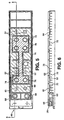
- FIGS. 13 and 14 show one embodiment of a battery of this invention with the cell components in place.
- Each of the six cells have a battery element comprising a series of alternately disposed positive and negative plates having separators positioned therebetween.
- the particular configuration and the number of plates and the respective size can be varied as desired for the particular application.
- the present invention can be used whether the lead-acid battery is of the flooded electrolyte or sealed type (i.e., a VRLA or valve-regulated lead-acid).
- Suitable grids and alloys are known and may be used, as are appropriate separator materials.
- appropriate strap alloys and intercell weld techniques are known and may be employed.
- positive terminal cell 36 (FIG. 14) includes positive plates 98 having lugs 100 electrically connected together by strap 102. Negative plates 104 similarly have lugs 106.
- a post 108 is provided and is electrically contacted to bushing 66.
- Appropriate post formation techniques are known and may be utilized, as desired.
- the preferred embodiment likewise includes intercell connections so as to electrically connect the plates of appropriate polarity together from cell-to-cell, as is also known.
- intercell welds 110 connect terminal cells 36 and 38 with the appropriate center cells 40 and back cells 42, via conventional tombstones 112.
- back cells are electrically connected via a crossover intercell weld shown by arrow 114.
- the features of the present invention combine to provide a low profile battery having the terminals capable of being accessed from the front.
- Using the sloped heat seal approach in the terminal cells and locating the terminals in the cover allows, for a particular selected height for the battery, the use of grids and plates which can have an increased height, so as to achieve enhanced electrical performance, relative to the use of conventional lead-acid battery containers and different terminal locations.
- the height of the plates 98 and 104 that may be used will be restricted by the location of the terminals and the need to heat seal the cover to the container while still having a height for the battery container adequate to allow appropriate intercell connections.
- the present invention by using a sloped container and cover with the position of the terminals in the cover, combine to minimize the head space required in the terminal cells while still accommodating the container height needed for the appropriate intercell connections.
- the present invention may be utilized for any desired voltage and for any application where it is desired to utilize a cell or battery wherein taller plates are utilized, including for automotive applications.
- the preferred embodiment utilizes the front cells as the terminal cells, it should be appreciated that the advantages of using taller plates can be achieved when the terminals are located on the side and/or top of the battery. In such events, the terminals are located in the cover; and the container and cover slant upwardly from the container side wall which the side terminals are located. When top terminals are used, the slant is preferably upwardly from one side wall, but could be from the end wall(s) adjacent top terminal.
- the container wall and cover slopes are utilized in the terminal cells. This configuration allows the use of the taller plates, thereby achieving optimized capacity.
- the illustrative embodiment shows the respective slope surfaces extending from the container front wall to the first cell partition (i.e., the first cross-partition in the illustrative embodiment), the extent of the slope can be more or less, if desired. However, the preferred embodiment achieves about as shallow a slope (the shallower, the better for ease in heat sealing) as is considered generally practical, as well as providing strength and durability of the resulting battery. Thus, when the slope extends past the cell partition, the heat sealing of the cover to the container is made more complex. If such a configuration is used, it will generally be desirable to utilize a discontinuous slop and provide some flat sealing surface for the container-cover heat seal.
- the illustrative embodiment utilizes a composite, two-piece cover that is preferred due to molding, appearance and assembly considerations.
- the two pieces could be combined; and a unitary cover employed.
- plugs over the terminal/post burn areas can be included, if desired, as is known.
- Such a unitary cover can likewise include, if desired, open electrolyte fill/vent holes and appropriate fill/vent covers, also as are known.
- the preferred embodiment comprises a VRLA lead-acid battery.
- the present invention may likewise be employed for other types of batteries.
- the present invention may be used with other immobilized electrolyte batteries, one example being lead-acid gel batteries, are known.
Landscapes
- Chemical & Material Sciences (AREA)
- Chemical Kinetics & Catalysis (AREA)
- Electrochemistry (AREA)
- General Chemical & Material Sciences (AREA)
- Engineering & Computer Science (AREA)
- Manufacturing & Machinery (AREA)
- Sealing Battery Cases Or Jackets (AREA)
- Connection Of Batteries Or Terminals (AREA)
Claims (9)
Applications Claiming Priority (3)
| Application Number | Priority Date | Filing Date | Title |
|---|---|---|---|
| US373330 | 1982-04-30 | ||
| US09/373,330 US6372382B2 (en) | 1999-08-21 | 1999-08-21 | Low profile front terminal lead-acid battery |
| PCT/US2000/021725 WO2001015248A1 (en) | 1999-08-21 | 2000-08-09 | Low profile front terminal lead-acid battery |
Publications (2)
| Publication Number | Publication Date |
|---|---|
| EP1214747A1 EP1214747A1 (de) | 2002-06-19 |
| EP1214747B1 true EP1214747B1 (de) | 2004-05-19 |
Family
ID=23471945
Family Applications (1)
| Application Number | Title | Priority Date | Filing Date |
|---|---|---|---|
| EP00952676A Expired - Lifetime EP1214747B1 (de) | 1999-08-21 | 2000-08-09 | Flacher bleiakkumulator mit vorderseitiger polklemme |
Country Status (8)
| Country | Link |
|---|---|
| US (1) | US6372382B2 (de) |
| EP (1) | EP1214747B1 (de) |
| JP (1) | JP5021878B2 (de) |
| AU (1) | AU774747B2 (de) |
| CA (1) | CA2376347C (de) |
| DE (1) | DE60010908T2 (de) |
| HK (1) | HK1047192B (de) |
| WO (1) | WO2001015248A1 (de) |
Families Citing this family (8)
| Publication number | Priority date | Publication date | Assignee | Title |
|---|---|---|---|---|
| USD480356S1 (en) | 2001-08-01 | 2003-10-07 | Matsushita Electric Industrial Co., Ltd. | Battery |
| US20030049521A1 (en) * | 2001-09-11 | 2003-03-13 | Japan Storage Battery Co., Ltd. | Lead acid battery |
| US6824916B2 (en) * | 2002-05-16 | 2004-11-30 | Motorola, Inc. | Hybrid battery housing |
| ITVI20040092A1 (it) * | 2004-04-21 | 2004-07-21 | Biasin Srl | Coperchio per contenitori di accumulatori |
| US8372537B2 (en) * | 2008-06-03 | 2013-02-12 | C&D Technologies, Inc. | Battery with a molded in-front terminal |
| LU91662B1 (en) * | 2010-03-11 | 2011-09-12 | Accumalux S A | Lid for a VRLA battery |
| ES2794017T3 (es) * | 2011-10-11 | 2020-11-17 | Zhejiang Narada Power Source | Sistema de caja, batería y bastidor de batería con apilamiento mejorado |
| CN110021777B (zh) * | 2018-01-08 | 2021-03-26 | 比亚迪股份有限公司 | 极芯、电池单元、电池模组及汽车 |
Family Cites Families (19)
| Publication number | Priority date | Publication date | Assignee | Title |
|---|---|---|---|---|
| US1508926A (en) | 1921-10-08 | 1924-09-16 | Westinghouse Union Battery Com | Storage-battery-cell cover |
| BE792980A (fr) | 1971-12-20 | 1973-04-16 | Gould Inc | Ensemble polaire lateral pour batterie |
| US3883369A (en) | 1973-12-26 | 1975-05-13 | Eltra Corp | Battery assembly machine |
| US4331747A (en) * | 1979-07-20 | 1982-05-25 | Chloride Group Limited | Electric storage batteries |
| US4278742A (en) | 1980-05-05 | 1981-07-14 | General Battery Corporation | Manifold vented battery cover |
| US4444853A (en) * | 1983-07-01 | 1984-04-24 | Globe-Union Inc. | Storage battery construction |
| AU570352B2 (en) | 1985-01-17 | 1988-03-10 | Furukawa Denchi Kabushiki Kaisha | Reduced height electrodes in storage battery |
| JPH0690920B2 (ja) * | 1985-01-25 | 1994-11-14 | 古河電池株式会社 | 蓄電池 |
| US4693949A (en) | 1985-08-12 | 1987-09-15 | Douglas Battery Manufacturing Co. | Storage battery housing |
| US4645725A (en) | 1985-08-30 | 1987-02-24 | Gnb Incorporated | Battery comprising dual terminal bushings |
| US4883728A (en) * | 1987-03-03 | 1989-11-28 | Pita Witehira | Battery systems |
| US5169735A (en) * | 1987-03-03 | 1992-12-08 | Pita Witehira | Automotive battery and electrical system |
| US5162164A (en) * | 1989-06-12 | 1992-11-10 | Globe-Union Inc. | Dual battery system |
| US5197994A (en) | 1990-11-26 | 1993-03-30 | Daniell Battery Manufacturing Co., Inc. | Method of heat sealing a battery |
| US5181936A (en) | 1991-09-03 | 1993-01-26 | General Motors Corporation | Process for heat sealing a cover to a container |
| US5223351A (en) * | 1991-11-14 | 1993-06-29 | Globe-Union Inc. | Dual battery system |
| JP3384007B2 (ja) * | 1992-11-17 | 2003-03-10 | 株式会社ユアサコーポレーション | 鉛蓄電池 |
| JPH0877984A (ja) * | 1994-08-31 | 1996-03-22 | Japan Storage Battery Co Ltd | 蓄電池 |
| US5686202A (en) * | 1995-10-18 | 1997-11-11 | Hawker Energy Products, Inc. | Stress resistant battery configuration |
-
1999
- 1999-08-21 US US09/373,330 patent/US6372382B2/en not_active Expired - Lifetime
-
2000
- 2000-08-09 WO PCT/US2000/021725 patent/WO2001015248A1/en not_active Ceased
- 2000-08-09 HK HK02108467.5A patent/HK1047192B/en not_active IP Right Cessation
- 2000-08-09 EP EP00952676A patent/EP1214747B1/de not_active Expired - Lifetime
- 2000-08-09 JP JP2001519508A patent/JP5021878B2/ja not_active Expired - Lifetime
- 2000-08-09 AU AU65330/00A patent/AU774747B2/en not_active Expired
- 2000-08-09 DE DE60010908T patent/DE60010908T2/de not_active Expired - Lifetime
- 2000-08-09 CA CA002376347A patent/CA2376347C/en not_active Expired - Lifetime
Also Published As
| Publication number | Publication date |
|---|---|
| HK1047192A1 (en) | 2003-02-07 |
| DE60010908D1 (de) | 2004-06-24 |
| DE60010908T2 (de) | 2005-05-19 |
| WO2001015248A1 (en) | 2001-03-01 |
| EP1214747A1 (de) | 2002-06-19 |
| JP5021878B2 (ja) | 2012-09-12 |
| AU774747B2 (en) | 2004-07-08 |
| HK1047192B (en) | 2004-11-26 |
| AU6533000A (en) | 2001-03-19 |
| US6372382B2 (en) | 2002-04-16 |
| JP2003508878A (ja) | 2003-03-04 |
| CA2376347A1 (en) | 2001-03-01 |
| US20020012835A1 (en) | 2002-01-31 |
| CA2376347C (en) | 2009-03-03 |
Similar Documents
| Publication | Publication Date | Title |
|---|---|---|
| US7811701B2 (en) | Battery assembly | |
| US4883728A (en) | Battery systems | |
| CA2120441C (en) | Sealed lead-acid cell tray assembly and motive powered vehicle using such cell tray assembly | |
| US6551741B1 (en) | Battery module | |
| US3941615A (en) | Battery construction | |
| CN106531953B (zh) | 铅酸蓄电池及电池组 | |
| CA2402455A1 (en) | Valve regulated lead acid battery | |
| EP1214747B1 (de) | Flacher bleiakkumulator mit vorderseitiger polklemme | |
| US20250096403A1 (en) | Battery module, battery pack, and vehicle | |
| WO2003015194A1 (fr) | Batterie fermee a decrochement angulaire | |
| CA1177115A (en) | Battery intercell connector manifold | |
| US20200259131A1 (en) | Monoblocs and monobloc batteries | |
| EP0370534B1 (de) | Batteriesysteme | |
| CN204011515U (zh) | 一种快速更换单体电池的电池组 | |
| AU3847101A (en) | Low profile six-volt lead-acid battery with front terminals | |
| CN223109069U (zh) | 电池箱体及电池包 | |
| CN222365652U (zh) | 电池单体、电池装置和用电装置 | |
| RU2233014C2 (ru) | Комбинированная конструкция для аккумулятора | |
| WO2001006590A1 (en) | A family of lead-acid batteries using a standardized container and having voltage that can be preselected as necessary | |
| CN118867536A (zh) | 电池箱体及电池包 | |
| JPH08264172A (ja) | ニッケル水素蓄電池 | |
| JPS604550B2 (ja) | 鉛蓄電池の製造法 | |
| JPH09219187A (ja) | 密閉形蓄電池 | |
| JPH0785856A (ja) | 密閉型鉛蓄電池 | |
| JP2000299090A (ja) | リテーナ式モノブロック電池 |
Legal Events
| Date | Code | Title | Description |
|---|---|---|---|
| PUAI | Public reference made under article 153(3) epc to a published international application that has entered the european phase |
Free format text: ORIGINAL CODE: 0009012 |
|
| 17P | Request for examination filed |
Effective date: 20020319 |
|
| AK | Designated contracting states |
Kind code of ref document: A1 Designated state(s): AT BE CH CY DE DK ES FI FR GB GR IE IT LI LU MC NL PT SE |
|
| GRAP | Despatch of communication of intention to grant a patent |
Free format text: ORIGINAL CODE: EPIDOSNIGR1 |
|
| GRAS | Grant fee paid |
Free format text: ORIGINAL CODE: EPIDOSNIGR3 |
|
| GRAA | (expected) grant |
Free format text: ORIGINAL CODE: 0009210 |
|
| AK | Designated contracting states |
Kind code of ref document: B1 Designated state(s): DE FR GB IT |
|
| REG | Reference to a national code |
Ref country code: GB Ref legal event code: FG4D |
|
| REG | Reference to a national code |
Ref country code: IE Ref legal event code: FG4D |
|
| REF | Corresponds to: |
Ref document number: 60010908 Country of ref document: DE Date of ref document: 20040624 Kind code of ref document: P |
|
| REG | Reference to a national code |
Ref country code: HK Ref legal event code: GR Ref document number: 1047192 Country of ref document: HK |
|
| ET | Fr: translation filed | ||
| PLBE | No opposition filed within time limit |
Free format text: ORIGINAL CODE: 0009261 |
|
| STAA | Information on the status of an ep patent application or granted ep patent |
Free format text: STATUS: NO OPPOSITION FILED WITHIN TIME LIMIT |
|
| REG | Reference to a national code |
Ref country code: IE Ref legal event code: MM4A |
|
| 26N | No opposition filed |
Effective date: 20050222 |
|
| REG | Reference to a national code |
Ref country code: GB Ref legal event code: 732E Free format text: REGISTERED BETWEEN 20160331 AND 20160406 |
|
| REG | Reference to a national code |
Ref country code: GB Ref legal event code: 732E Free format text: REGISTERED BETWEEN 20160407 AND 20160413 |
|
| REG | Reference to a national code |
Ref country code: FR Ref legal event code: PLFP Year of fee payment: 17 |
|
| REG | Reference to a national code |
Ref country code: FR Ref legal event code: PLFP Year of fee payment: 18 |
|
| REG | Reference to a national code |
Ref country code: FR Ref legal event code: PLFP Year of fee payment: 19 |
|
| REG | Reference to a national code |
Ref country code: GB Ref legal event code: 732E Free format text: REGISTERED BETWEEN 20190711 AND 20190717 |
|
| PGFP | Annual fee paid to national office [announced via postgrant information from national office to epo] |
Ref country code: IT Payment date: 20190821 Year of fee payment: 20 Ref country code: FR Payment date: 20190711 Year of fee payment: 20 Ref country code: DE Payment date: 20190730 Year of fee payment: 20 |
|
| PGFP | Annual fee paid to national office [announced via postgrant information from national office to epo] |
Ref country code: GB Payment date: 20190814 Year of fee payment: 20 |
|
| REG | Reference to a national code |
Ref country code: DE Ref legal event code: R071 Ref document number: 60010908 Country of ref document: DE |
|
| REG | Reference to a national code |
Ref country code: GB Ref legal event code: PE20 Expiry date: 20200808 |
|
| PG25 | Lapsed in a contracting state [announced via postgrant information from national office to epo] |
Ref country code: GB Free format text: LAPSE BECAUSE OF EXPIRATION OF PROTECTION Effective date: 20200808 |