EP1214238B1 - Zusammenklappbarer wagen - Google Patents
Zusammenklappbarer wagen Download PDFInfo
- Publication number
- EP1214238B1 EP1214238B1 EP00936961A EP00936961A EP1214238B1 EP 1214238 B1 EP1214238 B1 EP 1214238B1 EP 00936961 A EP00936961 A EP 00936961A EP 00936961 A EP00936961 A EP 00936961A EP 1214238 B1 EP1214238 B1 EP 1214238B1
- Authority
- EP
- European Patent Office
- Prior art keywords
- lateral members
- members
- lateral
- wheels
- trolley
- Prior art date
- Legal status (The legal status is an assumption and is not a legal conclusion. Google has not performed a legal analysis and makes no representation as to the accuracy of the status listed.)
- Expired - Lifetime
Links
Images


Classifications
-
- B—PERFORMING OPERATIONS; TRANSPORTING
- B62—LAND VEHICLES FOR TRAVELLING OTHERWISE THAN ON RAILS
- B62B—HAND-PROPELLED VEHICLES, e.g. HAND CARTS OR PERAMBULATORS; SLEDGES
- B62B3/00—Hand carts having more than one axis carrying transport wheels; Steering devices therefor; Equipment therefor
- B62B3/02—Hand carts having more than one axis carrying transport wheels; Steering devices therefor; Equipment therefor involving parts being adjustable, collapsible, attachable, detachable or convertible
-
- B—PERFORMING OPERATIONS; TRANSPORTING
- B62—LAND VEHICLES FOR TRAVELLING OTHERWISE THAN ON RAILS
- B62B—HAND-PROPELLED VEHICLES, e.g. HAND CARTS OR PERAMBULATORS; SLEDGES
- B62B2205/00—Hand-propelled vehicles or sledges being foldable or dismountable when not in use
- B62B2205/12—Collapsible wheels
-
- B—PERFORMING OPERATIONS; TRANSPORTING
- B62—LAND VEHICLES FOR TRAVELLING OTHERWISE THAN ON RAILS
- B62B—HAND-PROPELLED VEHICLES, e.g. HAND CARTS OR PERAMBULATORS; SLEDGES
- B62B3/00—Hand carts having more than one axis carrying transport wheels; Steering devices therefor; Equipment therefor
- B62B3/14—Hand carts having more than one axis carrying transport wheels; Steering devices therefor; Equipment therefor characterised by provisions for nesting or stacking, e.g. shopping trolleys
- B62B3/1476—Hand carts having more than one axis carrying transport wheels; Steering devices therefor; Equipment therefor characterised by provisions for nesting or stacking, e.g. shopping trolleys the main load support being a platform
Definitions
- the invention relates to a cart of the foldable type.
- carriage should be understood in its most general meaning. These are all devices including a platform or lower plate, usually fitted with two pairs of low wheels diameter Usually also the wheels of one of the pairs, usually the wheels at the end of the plate which will be arbitrarily called “front”, are say “crazy”, because they can rotate freely around an axis orthogonal to the plane formed by the lower plate. This arrangement allows more easy from the cart, as it allows it to turn to avoid obstacles or follow a winding path.
- the carriage is finally provided with a handle-type member, known as "folder” in terms of profession, in the shape of an inverted “U”, the ends of which branches are mechanically coupled on both sides of the other end of the tray, or rear end.
- the backrest can take two extreme positions: a so-called “ work ", in which it is substantially orthogonal to the plane of the plate or slightly inclined backwards, with respect to an axis orthogonal to this plate, and a so-called “rest” position, in which it is folded back onto the platform and substantially parallel to it.
- Locking means are provided reversible to lock the backrest, at least for the working position. Thanks to this arrangement, an operator can push or pull the cart by hand, thanks to the horizontal part of the inverted "U” forming the handle itself.
- this type of cart is commonly used to transport parts or objects relatively heavy and bulky: pieces of fabric, metal pieces, oars paper, etc.
- These trolleys are also used for domestic transport boxes, suitcases, etc.
- FIGS. 1A and 1B placed at the end of the present description, schematically illustrate an example of a carriage according to the known art, in working positions under the reference 1a and at rest under the reference 1B.
- a carriage essentially comprises a lower plate 10, or loading base, low compared to the ground S.
- the plate 10 rests on two pairs of wheels, arranged substantially at the four corners of the plate 10: a pair of fixed wheels at the rear, of which only one, 14, is visible in FIGS. 1A and 1B, and a pair of pivoting wheels at the front, movable in rotation about an axis ⁇ V orthogonal to the plate 10, of which only one, 15 is visible.
- the wheels, 14 or 15 respectively, are arranged inside supports, 13 and 15 respectively, in the shape of a "U".
- the rear supports, for example 13, are fixed and subject to the plate 10.
- the front supports, for example 15, are movable about an axis ⁇ V orthogonal to the plate 10, that is to say vertical in the working position of carriage 1a. To do this, an axis of rotation or a ball bearing seat, for example 150 for the support 15, is provided.
- the residual height h of the carriage 1b remains large: it equals a cumulative height representing the height of the wheels (diameter) and their supports, the thickness of the plate 10 and the residual height of the backrest (and its possible curvature in the handle area 110b) or the height of the member 12 (depending on the relative importance of these two heights)
- the residual height (or thickness) of the carriage 1b, in the rest position is typically 230 mm.
- US-A-4274644 shows a foldable cart.
- the main objective of the invention is to provide a carriage which, while retaining the general structure of the devices of the known art and their advantages and their usefulness, does not have the disadvantages of these devices, some of which have been recalled.
- the wheels of the carriage are retractable. More specifically, they are folded against the lower wall, when the carriage is in the rest position, that is, not used.
- the folding and unfolding movements of the wheels are synchronous with those in the file, and more precisely are caused by them.
- the folding of the wheels (folded position) is caused by the folding from the backrest to the tray, to reach the rest position.
- the unfolding of the wheels, to reach the normal rolling position is obtained just as simply by deploying the folder.
- Locking / unlocking means are provided, not only backrest, but also wheels in folded or unfolded positions. These means include in particular a triangular structure of longitudinal members, underlying the tray and actuated by tubes or side rails of the backrest. This structure is provided with a hand-operable member making it possible to obtain the unlocking, member arranged near the front end of the plate.
- the backrest is recessed, laterally, in the thickness of the plate, when the carriage is in the position rest. Only protrudes forward the horizontal part of the backrest or handle. This part constitutes a gripping member making it possible to transport easily by hand the carriage, in the rest position, that is to say folded.
- the carriage comprising advantageously front wheels movable in rotation about an axis, provides automatic plating members for these movable wheels against the lower wall of the plate, when the wheels pass from the unfolded position (state operational or work) in the folded (or rest) position.
- the embedding of the backrest structure in the volume of the tray makes it possible to surplus to obtain a substantially planar upper wall.
- This provision and the causes the seat to become substantially flat due to the folding of the wheels pressed against the bottom wall of the tray, are such as to allow easy storage of the trolley, vertical in a cupboard or similar, but also flat (for example in the trunk of a car).
- Trolleys stored horizontally are stackable, or allow the placing of objects on the upper wall of the tray, since it is substantially flat and horizontal.
- Unfolding, folding, locking and unlocking the backrest and the wheels is easy. They are almost automatic since a single operation synchronizes the wheel and backrest movements.
- the main object of the invention is therefore a foldable cart comprising a tray structure for transporting objects, and a folding backrest, arranged at a so-called front end of the carriage, comprising a first position, called a work, in which it is deployed in a direction substantially orthogonal to said tray structure, and a folded position, called a rest position, for which it is folded towards said tray structure, this structure resting on at least two pairs of wheel supports and associated wheels, of which a first pair disposed in an area close to said end front, characterized in that said tray structure comprises a frame consisting of a pair of first lateral uprights and two so-called uprights front and rear, and a central platform of substantially rectangular shape, leaving a free space between its lateral flanks and said lateral uprights, in that said file includes two lateral uprights including the end zones lower are arranged between said first lateral uprights and said platform central, in said free space, and are mechanically coupled to these first lateral uprights and / or to said central platform by axes of rotation,
- FIGS. 2A to 2D We will now describe in detail an example of a trolley according to a preferred embodiment of the invention with reference to FIGS. 2A to 2D.
- the elements common to these figures have the same references and will only be described again as needed.
- FIG. 2A illustrates the carriage, now referenced 2, in plan view and in perspective.
- the trolleys of the known art comprises a loading platform or tray, under the references 3 and 6, mounted on two pairs of wheels: a pair of fixed wheels, 41 and 42, at the rear of the plate 3-6, and a pair of front wheels, 43 and 44, movable in rotation about an axis ⁇ V , orthogonal to the plane of the plate, that is to say vertical if the carriage 2 is placed on a horizontal S floor.
- the plate consists of a rigid frame 3 formed of a pair of side members, front 30 and rear 31, of rectangular or square section, joined by two lateral tubes, 32 and 34, of circular section, and a central support plate proper 6.
- the latter comprises a flat wall 60, reinforced at the periphery (FIG. 2B: reference 61) and secured, at the front and at the rear of the plate, to the side members 30 and 31 , respectively.
- the wheels 41 to 44 are inserted into supports, respectively 45 to 48, conventionally in the form of a "U" as in the known art.
- the supports are not directly fixed or mechanically coupled to the plate. They are fixed or mechanically coupled by means of two lateral beams or beams, 33 and 35, of rectangular or square section.
- the rear supports, 47 and 48 are rigidly fixed to these beams.
- the front supports, 45 and 46 are mechanically coupled using members (not shown in FIGS. 2A to 2C), of a type similar to those of the prior art, allowing the above-mentioned rotation around the axis ⁇ V.
- the lateral beams, 33 and 35 are in turn mechanically coupled, at their two ends, to the front and rear beams, 30 and 31, by means of axes of rotation which will be described in more detail below.
- This arrangement allows rotation of the side rails ,. 33 and 35, and therefore supports, 45 to 48, as well as definitively wheels, 41 to 44, around two axes, ⁇ H1 and ⁇ H2 , substantially parallel to the plane of the plate (wall 60), as it will be described with reference to FIG. 2C.
- the carriage 2 also includes, in a similar manner to the prior art, a folding backrest 8.
- This has the general shape of an inverted “U” comprising a horizontal part 82, forming a handle.
- the backrest 8 is raised and substantially parallel to the axis ⁇ V (branches 80 and 81), that is to say a priori vertical, or is slightly tilted towards the 'rear with respect to this axis.
- FIG. 2B represents the carriage 2 in perspective, seen from below, still in operational condition (wheels, 41 to 44, and file 8 deployed).
- wheels, 41 to 44, and file 8 deployed We have shown in this figure 2B a mechanical structure 7, in a triangle, which allows lock the wheels and their supports in the working position, and unlock when you want to obtain the rest position.
- This structure Mechanical 7 will be described in more detail below.
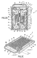
- FIGS. 2C and 2D represent the carriage 2 in the rest position, that is to say not only the folder 8 folded back, but, in accordance with one of the important characteristics of the invention, also the assemblies 4, wheels and supports.
- FIG. 2C represents the carriage 2 in perspective, seen from above (the carriage 2 being placed horizontally on the ground S ), and FIG. 2D the carriage 2 in view from below (the carriage 2 being suspended vertically, for example carried by the hand M of an operator not shown).
- the branches, 80 and 81, of the backrest 8 are embedded in the thickness of the plate 3-6, in the enclosure left free between the flat wall 60 and the side tubes, 32 and 34. Only the upper zone close to the handle 82 protrudes from the plateau. To do this, provision has been made on the amount before 30 notches, 300 and 301, of section adapted to the section of the tubes 80 and 81.
- This organ 76 may include a spring pawl 760 ( Figure 2B) which sinks into an opening (not shown in FIGS. 2B or 2D) produced in the tube 80 (in the example described) and which will be detailed below with regard to FIG. 6.
- the trolley is now in the non-operational or rest position. It can easily be seen, as illustrated more particularly in FIG. 2C, that the residual thickness h ′ of the carriage 2 is extremely small. It is reduced substantially to the thickness of the single plate 3-6, that is to say, in practical terms, substantially at the height of the front and rear uprights, 30 and 31. In the position shown in FIG. 2C, that is to say flat on the ground S (or on the floor of a car trunk for example), it is also found that the upper surface is substantially flat and horizontal. We can therefore deposit objects there.
- each of the side members side to which the wheel supports are attached is fitted on its end rear (near the lower end of the lateral uprights, 80 and 81, of the file 8) of an overflowing piece with a notch.
- the room end, 350 forms a wing extending the end face of the beam towards the interior of the carriage, as shown more particularly in FIG. 3D, in view front.
- the lateral uprights for example the upright 81, the only one shown in FIGS. 3A to 3E, comprises a stud 810 end (see Figure 3D) intended to be inserted in the notch 3500 which is fitted with part 350. The latter faces downwards.
- the lateral beams for example the beam 35, comprises axes of rotation at the two ends, mechanically coupling them to the end beams, respectively 30 and 31.
- one of the axes is shown, 351, extending the part 350 and intended to be inserted in an orifice (not shown) provided in the rear upright 31.
- This arrangement allows the spar 35 to rotate around the axis ⁇ H1 , and thus to drive the wheels and their supports so that they can fold or deploy, as will be shown more particularly with reference to Figures 3D and 3E. it is the same for the spar 33, around the axis ⁇ H2 .
- the amounts of file 8, for example the amount 81, are coupled mechanically to the side tubes, 32 or 34 (34 for the upright 81), and / or to the central support plate 6, by means of rotation axes arranged horizontally, for example the axis 340 (see Figure 3C).
- FIGS. 2B or 2D there is shown the locking and unlocking structure 7, general triangular shape.
- This triangular structure 7 comprises a central beam 70 parallel to the length of the carriage 2 and secured, by its two ends, to the side members rear 31 and front 30
- the lower ends of the uprights 80 and 81 are mechanically coupled to a tubular beam 73, forming the base of the triangle mentioned above and therefore orthogonal to the central beam 70.
- This mechanical coupling takes place via axes of rotation arranged horizontally, by example axis 730 for the upright 81, as illustrated more particularly by the detail figure 3C, side view.
- the two inclined sides of the triangle are made up of side members, 71 and 72, joining in a sleeve 75, sliding the along the central beam 70, and the function of which will be specified below.
- the detail figures 3B, in bottom view, and 3D, in front view, illustrate the working position of the upright 81, the rear wheel 44 and its support 48, as well as the upright 35 to which the support 48 is subject fixedly.
- the upright 81 is wedged between the tube 34 and the plate structure 6.
- the bottom of the upright 81 extends downward so that it rests on the internal face of the upright 35 and on the flank of the support 48.
- This arrangement forces the upright 35 to rotate about the axis ⁇ H1 and keeps it firmly in this position, that is to say the wheel 44 and its support 48 parallel to the axis ⁇ V ( a priori vertical, when the carriage 2 is placed on the ground S ).
- the wheel 44 is retained in the support 48 in the shape of a "U" overturned in a conventional manner by an axis of rotation symbolized by the reference 440.
- the uprights, 80 and 81, of the backrest 8 are substantially parallel to the axis ⁇ V , or slightly tilted backwards, as illustrated in FIG. 3C.
- the uprights for example the upright 81
- the uprights will rotate (at their lower end) around axes of rotation, for example the axis 340.
- the end studs for example the stud 810 for the upright 81
- the beam 35 will be rotated about the horizontal axis ⁇ H1 . It is the same for the spar 33, around the axis axis ⁇ H2 , which allows the wheels to be retracted.
- the spar 35 is shown during tilting. It drives the support 48 and the wheel 44, which is in a plane forming an angle ⁇ (different from 90 degrees) with the axis ⁇ V. This is also true for the front swivel wheels, 41 and 42.
- the lateral uprights wheel supports for example support 35
- the lateral uprights of the backrest 8 for example the upright 81
- the side tubes for example the tube 34
- the vertical uprights, 80 and 81 extend towards bottom and lean against the inner walls of the wheel supports, which one suppose planes, for example against the wall of the support 48 for the amount vertical 81 It follows that, the support 48 being fixedly fixed to the upright 35, the support 48 and the associated wheel 44, are firmly held, at this end of the carriage 2. It is naturally the same for the upright assembly 33, wheel support 47 and wheel 43.
- Figure 4B is a bottom view, in section of one of the uprights lateral wheel supports, in this case the lateral upright 35.
- a cam 37 is provided, with an axis of rotation 370, parallel to the axis ⁇ V.
- the cam 37 is advantageously provided with a triangular shape, the base 372 of which is rounded.
- a slot 354 is also provided in the internal vertical wall of the upright 35.
- the cam 37 is arranged in the operating region of the upright 81, so that, when the backrest 8 is in the working position, the upright 81 presses on the rounded base of the cam and pushes it towards the inside of the upright 35 (references 37 'and 372'), by rotation about the axis 370.
- the cam 37 drives a rod longitudinal 36, which extends from an axis of rotation, 371, arranged in a region near the top of the triangle of cam 37, at the front end 352 of the upright 35. In the rest position, the cam 37 has come out of the upright 35 and the rod 36 is pulled back. We arrange for the length of the rod 36 to be such that, in this position, it is flush with the front face of the upright 35.
- the above-mentioned elastic means can be constituted by a conventional spring, coaxial with the rod 36, disposed near the wall 352 and pushing the rod 36 towards the cam 37.
- the spring pushes the rod 36 towards the inside of the upright 35 and exerts a push on the cam 37, via rod 36
- Cam 37 rotates around axis 370 and the base is rounded 372 protrudes outward, as before.
- FIG. 4A is a detail figure, in perspective, of the front face of the upright 35 (in solid line).
- the front upright 30 of the carriage 2 has also been shown (in dotted lines).
- the amount 35 is inserted into this amount 30, by means of a rotation axis 353, in an orifice 302 provided for this purpose.
- This arrangement is found at the rear (axis of rotation 351), for the mechanical coupling between the upright 35 and the upright 31.
- the upright 35 can rotate around the axis of symmetry ⁇ H1 , as it l 'was previously shown (see Figures 3E for example).
- a second orifice is provided in the internal wall of the front upright 303 intended to receive the end of the rod 36.
- the end of the rod 36 is flush with the end wall 354 of the upright 35
- the cam when the cam is pushed inwardly of the upright 35 (reference 37 '), in its rotational movement around axis 370, it also pushes the rod forward (references 371 'and 36').
- the end of the latter protrudes from the wall 354 and is inserted into the orifice 303.
- the upright 35 can therefore no longer rotate freely around the axis of symmetry ⁇ H1 ., Since it there are two anchor points. Unlocking takes place, again automatically, when the backrest 8 is pushed forward (passage from the working position to the rest position), the rod 36 retracting.
- an automatic locking system is provided, but disengageable at the hand.
- the locking / unlocking system 7 essentially consists of a triangular structure.
- the base of the triangle includes a spar tubular 73 driven by the lower ends of the uprights, 80 and 81, of the folder 8.
- the two sides of the triangle are made up of side members, 71 and 72, mechanically coupled to a sleeve 75, disposed at the front of the carriage 2 and forming the top of the triangle. The latter slides along the central beam 70
- the beam 70 has an opening 701, on its two side walls, in the shape of an "L" reversed 90 °, facing the rear of the beam 70 (to the left in Figure 5).
- the sleeve 75 comprises a rod 750, arranged perpendicular to the length of the beam 70, introduced into the opening 701.
- a leaf-type spring 74, or any other elastic means, is also provided, attached to one end to the bottom wall of the beam 70. The free end of the latter is inserted into the sleeve 75, so as to exert a repulsive force F , tending to move it away from the bottom wall of the beam 70.
- the rod 750 is also arranged for the rod 750 to be opposite the notch formed by the vertical branch 7010 of the "L" upside down, when the backrest 8 is in the working position.
- the tubular beam 73 is pushed forward and it drives the sleeve 75 via the beams 71 and 72.
- the sleeve 75 is pushed towards the bottom and the rod 750 engages in the notch 7010.
- the spar 73 is supported on the bottom wall of the beam 70.
- Rod 750 comes out of its housing (reference 750 '). Then just push on the backrest 8 (for example on the handle 82) to unlock it and tilt it forward The rod (reference 750 ') then slides into the elongated branch 7011 of the "L", driving the sleeve (reference 75 ').
- This operation automatically causes other actions, such as previously described: unlocking the side uprights and folding the wheels.
- a groove 700 is provided, in an area rear of the beam 70.
- the exact position of this groove 700 is such that when the backrest 8 is folded down (rest position), the side member, here referenced 73 ′, engages in this recess 700.
- the rear wall, 7001, of the groove 700 is substantially vertical to a longitudinal axis of the beam 70 and its front wall, 7000, gently sloping, allowing engagement and easy disengagement of the beam 73-73 'when it goes from the working position to the rest position, and vice versa.
- the ratchet system 76 is advantageously arranged in a corner of the platform structure 6, against the front upright 30.
- a hole 800 is provided in the tube forming the lateral upright 80, into which engages a stud, rounded in end, actuated by a spring 761 arranged inside the ratchet system 76.
- the stud 7601 snaps into the hole 800 and maintains the upright 80, and therefore the backrest 8, embedded in the structure of tray 3-6.
- To unlock the backrest 8 just exert a force high enough to overcome the force of spring 761. Due to the shape rounded stud 760, the latter disengages from hole 800, and backrest 8 can to be relieved.
- the numerical values have only been specified to fix ideas. They essentially depend on the precise application targeted. Of even, the number of pairs of wheels could be greater than two: by example, we could provide a pair of intermediate wheel for a carriage great length. Neither is it necessary for the front wheels to be pivoting, for example if, in the intended application, the carriage moves on a substantially straight path.
Claims (9)
- Zusammenklappbarer Wagen, umfassend eine Plattenkonstruktion für den Transport von Gegenständen und einen umklappbaren Stirnbügel, der an einem, so genannten vorderen Ende des Wagens angeordnet ist, der eine erste, Arbeitsstellung genannte Stellung, in der er in einer fast orthogonalen Richtung zu besagter Plattenkonstruktion entfaltet ist, und eine umgeklappte, Ruhestellung genannte Stellung, für die er gegen besagte Plattenkonstruktion heruntergedrückt ist, hat, wobei diese Konstruktion auf wenigstens zwei Paaren von Radgehäusen und den dazu gehörenden Rädern aufliegt, von denen ein erstes Paar in einem Bereich nahe besagten vorderen Endes angeordnet ist, dadurch gekennzeichnet, dass besagte Plattenkonstruktion einen Rahmen (3), der aus einem Paar erster seitlicher Träger (32, 34) und aus zwei Trägern, die vorderer (30) und hinterer (31) genannt werden, besteht, und eine zentrale Plattform (6) von etwa rechteckiger Form umfasst, die einen freien Raum zwischen ihren seitlichen Flanken und besagten seitlichen Trägern (32, 34) lässt, dadurch, dass besagter Stirnbügel (8) zwei seitliche Träger (80, 81) umfasst, deren untere Endbereiche zwischen besagten ersten seitlichen Trägern (32, 34) und besagter zentraler Plattform (6) in besagtem freien Raum angeordnet sind und mechanisch an diese ersten seitlichen Träger (32, 34) und/oder an besagte zentrale Plattform (6) über Rotationsachsen (340) gekoppelt sind, dadurch, dass besagte Radgehäuse (45-48) mechanisch an ein Paar zweiter seitlicher Träger (33-35) gekoppelt sind, die unter besagten ersten seitlichen Trägern (32, 34) angeordnet und um Achsen (351, 353) rotierend beweglich sind, die an besagten vorderen Träger (30) beziehungsweise besagten hinteren Träger (31) des Rahmens (3) gekoppelt sind, dadurch, dass die unteren Enden besagter seitlicher Träger (80, 81) des Stirnbügels (8) Mittel zum Betätigen (810) haben, die dazu bestimmt sind, Hebelmittel (350) zu bewegen, die an den so genannten vorderen Enden besagter zweiter seitlicher Träger (33, 35) angeordnet sind, um ihre Rotation um besagte Rotationsachsen (351, 353) zu bewirken, wenn besagter Stirnbügel (8) zum vorderen Teil des Wagens (2) hin gedrückt wird, um aus besagter Arbeitsstellung in besagte Ruhestellung überzugehen, und um gleichzeitig das Umklappen besagter Räder (41-44) gegen die Unterseite genannte Seite besagter zentraler Plattform (6) zu bewirken, und dadurch, dass, wobei besagte erste Radgehäuse (45-48) wenigstens eine ebene Wand, die zum Inneren des Wagens (2) hin gewandt ist, umfassen und besagte zweite seitliche Träger (33-35) einen quadratischen oder rechteckigen Querschnitt haben, die unteren Endbereiche besagter seitlicher Träger (80, 81) besagten Stirnbügels (8) nach unten verlängert sind, um gegen besagte ebene Wände der ersten Radgehäuse (45-48) und gegen die Wände besagter seitlicher Träger (33-35), die zum Innern des Wagens hin gewandt sind, zu drücken, wenn besagter Stirnbügel (8) aus besagter Ruhestellung in besagte Arbeitsstellung übergeht, und um besagte zweite seitliche Träger (33, 35) um ihre so genannten Rotationsachsen (351, 353) zu schwenken, um besagte Radgehäuse (45-48) und die Räder (41-44), die zu ihnen gehören, zu entfalten und sie fest in einer ausgeklappten Stellung zu halten.
- Zusammenklappbarer Wagen gemäß Anspruch 1, dadurch gekennzeichnet, dass besagte Mittel zum Betätigen aus Zapfen (851) bestehen, die die unteren Enden besagter seitlicher Träger (80, 81) des Stirnbügels (8) verlängern, und die einen Hebel bildenden Mittel aus einer Zunge (350) bestehen, die am so genannten hinteren Ende besagter zweiter seitlicher Träger (33, 35) befestigt ist, zum Innern des Wagens (2) hin herausragt und eine Kerbe (3500) mit zu besagtem Zapfen (851) paariger Form hat, und in die dieser hineingreift.
- Zusammenklappbarer Wagen gemäß einem der Ansprüche 1 oder 2, dadurch gekennzeichnet, dass besagte zweite seitliche Träger (33, 35) ein System mit innerer Kurvenscheibe (37) umfassen, die jeweils durch einen unteren Endbereich eines der besagten seitlichen Träger (80, 81) besagten Stirnbügels (8) bewegt wird, dadurch, dass besagte Kurvenscheiben (37) um Achsen (370) rotierend beweglich sind, dadurch, dass besagte zweite seitliche Träger (33, 35) Schlitze (354) haben, dadurch, dass besagte Kurvenscheiben (37) eine abgerundete Wand (372) umfassen, die teilweise durch besagten Schlitz (354) austritt, wenn besagte seitliche Träger (80, 81) besagten Stirnbügels (8) in besagter Ruhestellung sind, und nach innen weggedrückt ist, wenn besagte seitliche Träger (80, 81) besagten Stirnbügels (8) in besagter Arbeitsstellung sind, dadurch, dass für jeden der besagten zweiten seitlichen Träger (33, 35) ein Längsgestänge (36) vorgesehen ist, von dem ein erstes Ende über eine Rotationsachse (371) an eine der besagten Kurvenscheiben (37) gekoppelt ist, das sich bis zu besagtem vorderem Ende besagter zweiter seitlicher Träger (33, 35) erstreckt, wobei die zweiten Enden dieser Gestänge (36) in besagter Ruhestellung mit der Oberfläche der Stirnflächen des vorderen Endes (354) dieser zweiten seitlichen Träger (33, 35) bündig sind und in besagter Arbeitsstellung diese Stirnflächen des vorderen Endes (354) überragen, um in Löchern (303), die in besagten vorderen Träger (30) gemacht sind, zu versinken, wobei diese Gestängeenden (36') mit den vorderen Rotationsachsen (353) besagter zweiter seitlicher Träger (33, 35) zusammenwirken, um sie zu verriegeln und ihre Rotation in besagter Arbeitsstellung zu verhindern.
- Zusammenklappbarer Wagen gemäß einem der vorhergehenden Ansprüche, dadurch gekennzeichnet, dass die unteren Enden besagter seitlicher Träger (80, 81) besagten Stirnbügels (8) mechanisch über einen Querholm (73), der unter besagter Plattenkonstruktion (6) angeordnet ist, gekoppelt sind, dadurch, dass ein zentraler Längsträgerbalken (70) vorgesehen ist, der an seinen beiden Enden an besagtem vorderem Träger (30) beziehungsweise besagtem hinterem Träger (31) befestigt ist, dadurch, dass die Enden besagten Querholms (73) auch an die ersten Enden von zwei seitlichen Holmen (71, 72) gekoppelt sind, dadurch, dass die zweiten Enden dieser seitlichen Holme (71, 72) durch eine Manschette (75) vereinigt sind, die entlang besagten zentralen Längsträgerbalkens (70) gleitet, um eine dreieckige Konstruktion zu bilden, dadurch, dass besagter zentraler Längsträgerbalken (70) eine Öffnung (701) in Form eines umgedrehten "L" hat, dessen kurzer Arm eine erste Vertiefung (7010) und dessen langer Arm eine zweite Vertiefung (7011), die parallel zu einer Längsrichtung ist, bildet, dadurch, dass besagte Manschette (75) einen Stift (750) hat, der in besagte Öffnung (701) eingefügt ist, dadurch, dass elastische Mittel (74) vorgesehen sind, die eine abstoßende Kraft (F) ausüben, die darauf gerichtet ist, besagte Manschette (75) von der unteren Wand besagten zentralen Längsträgerbalkens (70) wegzuschieben, dadurch, dass, wenn besagte seitliche Träger (80, 81) besagten Stirnbügels (8) aus besagter Ruhestellung in besagte Arbeitsstellung übergehen, besagter Querholm (73) so mitgeführt 'wird, dass er selbst wiederum besagte Manschette (75) mittels besagter seitlicher Holme (71, 72) mitführt in eine Stellung, für die, da besagter Stift (750) besagter erster Vertiefung (7010) gegenübersteht und die Manschette (75) durch besagte elastische Mittel (74) zurückgedrückt wird, besagter Stift (750) in die erste Vertiefung (7010) einschnappt, die Manschette (75) in dieser Stellung blockiert bleibt und besagter Stirnbügel (8) in besagter Arbeitsstellung verriegelt ist, und dadurch, dass die Entriegelung erzielt wird, indem man manuell eine Druckkraft (F) auf die Unterseite besagter Manschette (75) ausübt, um besagten Stift (750) aus besagter erster Vertiefung (7010) zu ziehen und ihn entlang besagter zweiter Vertiefung (7011) gleiten zu lassen.
- Zusammenklappbarer Wagen gemäß Anspruch 4, dadurch gekennzeichnet, dass besagte elastische Mittel aus einem Federblatt (74) bestehen, das an einem Ende an der unteren Wand besagten zentralen Längsträgerbalkens (70) befestigt ist und dessen freies Ende zwischen dieser Wand und besagter Manschette (75) eingefügt ist.
- Zusammenklappbarer Wagen gemäß einem der vorhergehenden Ansprüche, dadurch gekennzeichnet, dass, da das Räderpaar (41, 42), das vorne am Wagen angeordnet ist, um eine Achse (ΔV), die zu einer Längsrichtung besagter zweiter seitlicher Träger (33, 35) orthogonal ist, beweglich ist, besagte dazu gehörenden Radgehäuse (45, 46) mit Organen (51, 52), die Anschlagsorgane genannt werden, versehen sind, die aus Flügeln bestehen, die besagte Gehäuse überragen, damit, wenn besagter Stirnbügel (8) aus besagter Arbeitsstellung in besagte Ruhestellung übergeht, wobei er besagte zweite seitliche Träger (33, 35) und besagte Radgehäuse (45, 46) drehend mitführt, besagte Anschlagsorgane (51, 52) die besagten Radgehäuse (45, 46) in die richtige Stellung bringen, um das Zusammenklappen zu ermöglichen, und dann, wenn besagte Ruhestellung erreicht ist, die Räder (41, 42) und ihre Gehäuse (45, 46) in einer eingeklappten Stellung, gegen die Unterseite besagter zentraler Plattform (6) gedrückt, halten.
- Zusammenklappbarer Wagen gemäß einem der vorhergehenden Ansprüche, dadurch gekennzeichnet, dass, da besagte seitliche Träger (80, 81) besagten Stirnbügels (8) eine solchen Länge haben, dass sie in besagter Ruhestellung vorne über den Wagen (2) herausragen, besagter vorderer Träger (30) des Rahmens (3) an seiner Oberseite Vertiefungen (300, 301) hat, die dazu bestimmt sind, diese seitlichen Träger (80, 81) aufzunehmen, um das Versenken des Stirnbügels (8) in besagte Plattenkonstruktion (3-6) zu ermöglichen.
- Zusammenklappbarer Wagen gemäß Anspruch 7, dadurch gekennzeichnet, dass, wobei wenigstens einer der besagten seitlichen Träger (80) besagten Stirnbügels (8) eine Öffnung (800) hat, er außerdem ein Sperrklinkensystem (76) umfasst, das einen abgerundeten Stift (760) umfasst, der von einer Feder (761) bewegt wird, der in besagte Öffnung (800) einfährt, um besagten Träger (80), der in besagte Plattenkonstruktion (3-6) versenkt ist, zu verriegeln, wenn besagter Stirnbügel (8) in besagter Ruhestellung ist, und dadurch, dass das Entriegeln erzielt wird, indem man eine Zugkraft auf besagten Stirnbügel (8) zum hinteren Teil des Wagens (2) hin ausübt, um besagten Stift (760) aus besagter Öffnung (800) heraustreten zu lassen und besagten seitlichen Träger (80) freizugeben.
- Zusammenklappbarer Wagen gemäß einem der vorhergehenden Ansprüche, dadurch gekennzeichnet, dass ein Zubehör (9) zum Transport von Gegenständen vorgesehen ist, das reversibel an besagtem Stirnbügel (8) und/oder an besagter Plattenkonstruktion (3-6) eingehängt werden kann (90).
Applications Claiming Priority (3)
| Application Number | Priority Date | Filing Date | Title |
|---|---|---|---|
| FR9906861 | 1999-06-01 | ||
| FR9906861A FR2794417B1 (fr) | 1999-06-01 | 1999-06-01 | Chariot pliable |
| PCT/FR2000/001459 WO2000073122A1 (fr) | 1999-06-01 | 2000-05-29 | Chariot pliable |
Publications (2)
| Publication Number | Publication Date |
|---|---|
| EP1214238A1 EP1214238A1 (de) | 2002-06-19 |
| EP1214238B1 true EP1214238B1 (de) | 2004-08-11 |
Family
ID=9546203
Family Applications (1)
| Application Number | Title | Priority Date | Filing Date |
|---|---|---|---|
| EP00936961A Expired - Lifetime EP1214238B1 (de) | 1999-06-01 | 2000-05-29 | Zusammenklappbarer wagen |
Country Status (7)
| Country | Link |
|---|---|
| EP (1) | EP1214238B1 (de) |
| AT (1) | ATE273158T1 (de) |
| AU (1) | AU5227100A (de) |
| DE (1) | DE60012948T2 (de) |
| ES (1) | ES2226854T3 (de) |
| FR (1) | FR2794417B1 (de) |
| WO (1) | WO2000073122A1 (de) |
Families Citing this family (10)
| Publication number | Priority date | Publication date | Assignee | Title |
|---|---|---|---|---|
| DE10159706A1 (de) * | 2001-12-05 | 2003-06-18 | Drueke Claudia | Transportwagen |
| DE10240895A1 (de) * | 2002-09-04 | 2004-03-18 | Helmut Abel | Transportwagen mit Klapprädern und Deichsel |
| DE10257932B4 (de) * | 2002-12-12 | 2004-09-09 | Peter Westphal | Hankkarren |
| ES2345236B1 (es) * | 2008-09-29 | 2012-03-15 | Juan Luis Rodr�?Guez Santos | Carro plegable para subir la compra a la vivienda |
| DE202009004554U1 (de) * | 2009-04-02 | 2009-07-23 | Airbus Deutschland Gmbh | Platzsparend aufbewahrbarer Transportwagen zur Bestückung einer Flugzeugbordküche |
| GB2482688A (en) * | 2010-08-09 | 2012-02-15 | Trevor Neil Martin | A trolley which can collapse to have all the wheels in the same plane as the trolley |
| FR2987591B1 (fr) * | 2012-03-01 | 2018-02-02 | Psa Automobiles Sa. | Chariot de transport transformable a paire de jambes rabattables et roues rabattables simultanement |
| CN106476874B (zh) * | 2015-12-28 | 2018-07-24 | 陈昭胜 | 一种四连杆锁紧机构及其应用该机构的折叠手推车 |
| KR102027733B1 (ko) * | 2019-03-29 | 2019-10-01 | 송재호 | 접이식 사륜 핸드카트 |
| CN111572614B (zh) * | 2020-05-28 | 2021-04-20 | 安徽恒益纺织科技有限公司 | 一种用于面料卷筒的存放运输装置 |
Family Cites Families (3)
| Publication number | Priority date | Publication date | Assignee | Title |
|---|---|---|---|---|
| US4274644A (en) * | 1979-08-30 | 1981-06-23 | Taylor Frank E | Four wheeled hand truck |
| DE9114069U1 (de) * | 1991-11-11 | 1993-01-07 | Bielefelder Kuechenmaschinen- Und Transportgeraetefabrik Vom Braucke Gmbh, 4800 Bielefeld, De | |
| US5816604A (en) | 1997-05-27 | 1998-10-06 | Hsieh; Hung-Ching | Stretchable and foldable cart |
-
1999
- 1999-06-01 FR FR9906861A patent/FR2794417B1/fr not_active Expired - Fee Related
-
2000
- 2000-05-29 AU AU52271/00A patent/AU5227100A/en not_active Abandoned
- 2000-05-29 EP EP00936961A patent/EP1214238B1/de not_active Expired - Lifetime
- 2000-05-29 DE DE60012948T patent/DE60012948T2/de not_active Expired - Lifetime
- 2000-05-29 AT AT00936961T patent/ATE273158T1/de not_active IP Right Cessation
- 2000-05-29 ES ES00936961T patent/ES2226854T3/es not_active Expired - Lifetime
- 2000-05-29 WO PCT/FR2000/001459 patent/WO2000073122A1/fr active IP Right Grant
Also Published As
| Publication number | Publication date |
|---|---|
| ATE273158T1 (de) | 2004-08-15 |
| DE60012948T2 (de) | 2005-08-11 |
| AU5227100A (en) | 2000-12-18 |
| FR2794417A1 (fr) | 2000-12-08 |
| FR2794417B1 (fr) | 2001-08-17 |
| WO2000073122A1 (fr) | 2000-12-07 |
| ES2226854T3 (es) | 2005-04-01 |
| EP1214238A1 (de) | 2002-06-19 |
| DE60012948D1 (de) | 2004-09-16 |
Similar Documents
| Publication | Publication Date | Title |
|---|---|---|
| EP0577496B1 (de) | Kompakter zusammenklappbarer Kinderwagen | |
| FR2766446A3 (fr) | Chariot a main | |
| FR2792176A1 (fr) | Valise-chariot | |
| EP1214238B1 (de) | Zusammenklappbarer wagen | |
| EP2855234A1 (de) | Antiparallelogrammfaltstruktur, kinderwagen, sessel, stuhl, tisch, babytrage, wagen | |
| FR2829439A1 (fr) | Pietement de siege de vehicule, siege comportant un tel pietement et ensemble d'assise comportant un tel siege | |
| EP1693275A2 (de) | Schirmartig zusammenklappbarer Kinderwagen | |
| EP3755575A1 (de) | Kippbarer anhänger mit mechanischer betätigungsvorrichtung und hochpositionsverriegelungvorrichtung | |
| FR2648102A1 (fr) | Vehicule non autopropulse, notamment du genre poussette ou analogue | |
| WO2011069956A1 (fr) | Table à rallonge | |
| FR2839626A1 (fr) | Rayonnage equipe d'au moins une etagere mobile | |
| FR2666553A1 (fr) | Chariot equipe d'une partie de reception de marchandises reliee a un coulisseau mobile en hauteur, et dispositif de guidage pour ce coulisseau. | |
| EP2583653A1 (de) | Krankenbett mit entfernbarem Transportwagen | |
| FR2531018A1 (fr) | Dispositif de couverture mobile pour camions et autres vehicules | |
| EP2230149B1 (de) | Umwandelbarer Transportwagen mit einer Anschlussstruktur mit zwei Vierecken mit variabler Geometrie | |
| EP3317159B1 (de) | Doppelpedal zum zusammenklappen eines kinderwagens | |
| EP1055558A1 (de) | Ladeplattform | |
| FR2935366A1 (fr) | Conteneur a commande automatique. | |
| FR3036367A1 (fr) | Trottinette pliable | |
| FR3037010A1 (fr) | Siege escamotable muni de moyens d’entrainement disposes entre l’assise et le dossier et vehicule automobile comprenant un tel siege | |
| FR2708464A1 (fr) | Chariot-brancard comprenant un bâti et un brancard fixe de manière démontable sur le bâti. | |
| EP3286064B1 (de) | Klapprahmen eines kinderwagens und zugehöriger kinderwagen | |
| EP3978333B1 (de) | Manuell bedienbarer förderwagen | |
| FR2620994A1 (fr) | Chariot destine au transport de marchandises diverses | |
| FR2795652A1 (fr) | Chariot pliable pour sac de golf, possedant des moyens de verrouillage perfectionnes |
Legal Events
| Date | Code | Title | Description |
|---|---|---|---|
| PUAI | Public reference made under article 153(3) epc to a published international application that has entered the european phase |
Free format text: ORIGINAL CODE: 0009012 |
|
| 17P | Request for examination filed |
Effective date: 20020417 |
|
| AK | Designated contracting states |
Kind code of ref document: A1 Designated state(s): AT BE CH CY DE DK ES FI FR GB GR IE IT LI LU MC NL PT SE |
|
| AX | Request for extension of the european patent |
Free format text: AL;LT;LV;MK;RO;SI |
|
| 111L | Licence recorded |
Free format text: 20020619 0100 BKMF VOM BRAUCKE GMBH |
|
| GRAP | Despatch of communication of intention to grant a patent |
Free format text: ORIGINAL CODE: EPIDOSNIGR1 |
|
| GRAS | Grant fee paid |
Free format text: ORIGINAL CODE: EPIDOSNIGR3 |
|
| GRAA | (expected) grant |
Free format text: ORIGINAL CODE: 0009210 |
|
| AK | Designated contracting states |
Kind code of ref document: B1 Designated state(s): AT BE CH CY DE DK ES FI FR GB GR IE IT LI LU MC NL PT SE |
|
| PG25 | Lapsed in a contracting state [announced via postgrant information from national office to epo] |
Ref country code: FI Free format text: LAPSE BECAUSE OF FAILURE TO SUBMIT A TRANSLATION OF THE DESCRIPTION OR TO PAY THE FEE WITHIN THE PRESCRIBED TIME-LIMIT Effective date: 20040811 |
|
| REG | Reference to a national code |
Ref country code: GB Ref legal event code: FG4D Free format text: NOT ENGLISH |
|
| REG | Reference to a national code |
Ref country code: CH Ref legal event code: EP |
|
| REG | Reference to a national code |
Ref country code: IE Ref legal event code: FG4D Free format text: FRENCH |
|
| REF | Corresponds to: |
Ref document number: 60012948 Country of ref document: DE Date of ref document: 20040916 Kind code of ref document: P |
|
| PG25 | Lapsed in a contracting state [announced via postgrant information from national office to epo] |
Ref country code: SE Free format text: LAPSE BECAUSE OF FAILURE TO SUBMIT A TRANSLATION OF THE DESCRIPTION OR TO PAY THE FEE WITHIN THE PRESCRIBED TIME-LIMIT Effective date: 20041111 Ref country code: GR Free format text: LAPSE BECAUSE OF FAILURE TO SUBMIT A TRANSLATION OF THE DESCRIPTION OR TO PAY THE FEE WITHIN THE PRESCRIBED TIME-LIMIT Effective date: 20041111 Ref country code: DK Free format text: LAPSE BECAUSE OF FAILURE TO SUBMIT A TRANSLATION OF THE DESCRIPTION OR TO PAY THE FEE WITHIN THE PRESCRIBED TIME-LIMIT Effective date: 20041111 |
|
| REG | Reference to a national code |
Ref country code: CH Ref legal event code: NV Representative=s name: E. BLUM & CO. PATENTANWAELTE |
|
| GBT | Gb: translation of ep patent filed (gb section 77(6)(a)/1977) |
Effective date: 20041115 |
|
| REG | Reference to a national code |
Ref country code: ES Ref legal event code: FG2A Ref document number: 2226854 Country of ref document: ES Kind code of ref document: T3 |
|
| PG25 | Lapsed in a contracting state [announced via postgrant information from national office to epo] |
Ref country code: IT Free format text: LAPSE BECAUSE OF NON-PAYMENT OF DUE FEES Effective date: 20050529 Ref country code: CY Free format text: LAPSE BECAUSE OF FAILURE TO SUBMIT A TRANSLATION OF THE DESCRIPTION OR TO PAY THE FEE WITHIN THE PRESCRIBED TIME-LIMIT Effective date: 20050529 Ref country code: LU Free format text: LAPSE BECAUSE OF NON-PAYMENT OF DUE FEES Effective date: 20050529 |
|
| PG25 | Lapsed in a contracting state [announced via postgrant information from national office to epo] |
Ref country code: MC Free format text: LAPSE BECAUSE OF NON-PAYMENT OF DUE FEES Effective date: 20050531 |
|
| PLBE | No opposition filed within time limit |
Free format text: ORIGINAL CODE: 0009261 |
|
| STAA | Information on the status of an ep patent application or granted ep patent |
Free format text: STATUS: NO OPPOSITION FILED WITHIN TIME LIMIT |
|
| 26N | No opposition filed |
Effective date: 20050512 |
|
| REG | Reference to a national code |
Ref country code: CH Ref legal event code: PFA Owner name: DELABY, DANIEL JEAN Free format text: DELABY, DANIEL JEAN#136, AVENUE DE VERDUN#92130 ISSY LES MOULINEAUX (FR) $ SAGEON, CLAUDE#143, GRANDE RUE#92310 SEVRES (FR) -TRANSFER TO- DELABY, DANIEL JEAN#136, AVENUE DE VERDUN#92130 ISSY LES MOULINEAUX (FR) $ SAGEON, CLAUDE#143, GRANDE RUE#92310 SEVRES (FR) |
|
| PG25 | Lapsed in a contracting state [announced via postgrant information from national office to epo] |
Ref country code: PT Free format text: LAPSE BECAUSE OF NON-PAYMENT OF DUE FEES Effective date: 20050111 |
|
| PGRI | Patent reinstated in contracting state [announced from national office to epo] |
Ref country code: IT Effective date: 20090401 |
|
| PGFP | Annual fee paid to national office [announced via postgrant information from national office to epo] |
Ref country code: IE Payment date: 20100505 Year of fee payment: 11 Ref country code: ES Payment date: 20100531 Year of fee payment: 11 |
|
| PGFP | Annual fee paid to national office [announced via postgrant information from national office to epo] |
Ref country code: AT Payment date: 20100525 Year of fee payment: 11 Ref country code: IT Payment date: 20100528 Year of fee payment: 11 Ref country code: NL Payment date: 20100531 Year of fee payment: 11 |
|
| PGFP | Annual fee paid to national office [announced via postgrant information from national office to epo] |
Ref country code: CH Payment date: 20100518 Year of fee payment: 11 Ref country code: BE Payment date: 20100629 Year of fee payment: 11 |
|
| PGFP | Annual fee paid to national office [announced via postgrant information from national office to epo] |
Ref country code: GB Payment date: 20100504 Year of fee payment: 11 |
|
| BERE | Be: lapsed |
Owner name: *SAGEON CLAUDE Effective date: 20110531 Owner name: *DELABY DANIEL JEAN Effective date: 20110531 |
|
| REG | Reference to a national code |
Ref country code: NL Ref legal event code: V1 Effective date: 20111201 |
|
| REG | Reference to a national code |
Ref country code: CH Ref legal event code: PL |
|
| GBPC | Gb: european patent ceased through non-payment of renewal fee |
Effective date: 20110529 |
|
| PG25 | Lapsed in a contracting state [announced via postgrant information from national office to epo] |
Ref country code: LI Free format text: LAPSE BECAUSE OF NON-PAYMENT OF DUE FEES Effective date: 20110531 Ref country code: NL Free format text: LAPSE BECAUSE OF NON-PAYMENT OF DUE FEES Effective date: 20111201 Ref country code: CH Free format text: LAPSE BECAUSE OF NON-PAYMENT OF DUE FEES Effective date: 20110531 |
|
| REG | Reference to a national code |
Ref country code: AT Ref legal event code: MM01 Ref document number: 273158 Country of ref document: AT Kind code of ref document: T Effective date: 20110529 |
|
| PG25 | Lapsed in a contracting state [announced via postgrant information from national office to epo] |
Ref country code: AT Free format text: LAPSE BECAUSE OF NON-PAYMENT OF DUE FEES Effective date: 20110529 Ref country code: IT Free format text: LAPSE BECAUSE OF NON-PAYMENT OF DUE FEES Effective date: 20110529 |
|
| REG | Reference to a national code |
Ref country code: IE Ref legal event code: MM4A |
|
| PG25 | Lapsed in a contracting state [announced via postgrant information from national office to epo] |
Ref country code: BE Free format text: LAPSE BECAUSE OF NON-PAYMENT OF DUE FEES Effective date: 20110531 |
|
| PG25 | Lapsed in a contracting state [announced via postgrant information from national office to epo] |
Ref country code: IE Free format text: LAPSE BECAUSE OF NON-PAYMENT OF DUE FEES Effective date: 20110530 |
|
| PG25 | Lapsed in a contracting state [announced via postgrant information from national office to epo] |
Ref country code: GB Free format text: LAPSE BECAUSE OF NON-PAYMENT OF DUE FEES Effective date: 20110529 |
|
| REG | Reference to a national code |
Ref country code: ES Ref legal event code: FD2A Effective date: 20120717 |
|
| PG25 | Lapsed in a contracting state [announced via postgrant information from national office to epo] |
Ref country code: ES Free format text: LAPSE BECAUSE OF NON-PAYMENT OF DUE FEES Effective date: 20110530 |
|
| PGFP | Annual fee paid to national office [announced via postgrant information from national office to epo] |
Ref country code: FR Payment date: 20120621 Year of fee payment: 13 |
|
| PGFP | Annual fee paid to national office [announced via postgrant information from national office to epo] |
Ref country code: DE Payment date: 20120730 Year of fee payment: 13 |
|
| PG25 | Lapsed in a contracting state [announced via postgrant information from national office to epo] |
Ref country code: DE Free format text: LAPSE BECAUSE OF NON-PAYMENT OF DUE FEES Effective date: 20131203 |
|
| REG | Reference to a national code |
Ref country code: FR Ref legal event code: ST Effective date: 20140131 |
|
| REG | Reference to a national code |
Ref country code: DE Ref legal event code: R119 Ref document number: 60012948 Country of ref document: DE Effective date: 20131203 |
|
| PG25 | Lapsed in a contracting state [announced via postgrant information from national office to epo] |
Ref country code: FR Free format text: LAPSE BECAUSE OF NON-PAYMENT OF DUE FEES Effective date: 20130531 |