EP1214020B1 - Prothese destinee a la reparation d'un anevrisme de l'aorte abdominale - Google Patents
Prothese destinee a la reparation d'un anevrisme de l'aorte abdominale Download PDFInfo
- Publication number
- EP1214020B1 EP1214020B1 EP00965353A EP00965353A EP1214020B1 EP 1214020 B1 EP1214020 B1 EP 1214020B1 EP 00965353 A EP00965353 A EP 00965353A EP 00965353 A EP00965353 A EP 00965353A EP 1214020 B1 EP1214020 B1 EP 1214020B1
- Authority
- EP
- European Patent Office
- Prior art keywords
- tubular member
- space
- prosthetic device
- inflation
- tubular
- Prior art date
- Legal status (The legal status is an assumption and is not a legal conclusion. Google has not performed a legal analysis and makes no representation as to the accuracy of the status listed.)
- Expired - Lifetime
Links
- 230000008439 repair process Effects 0.000 title claims description 10
- 208000002223 abdominal aortic aneurysm Diseases 0.000 title description 15
- 208000007474 aortic aneurysm Diseases 0.000 title description 3
- 206010002329 Aneurysm Diseases 0.000 claims abstract description 26
- 239000012530 fluid Substances 0.000 claims abstract description 20
- 238000003780 insertion Methods 0.000 claims abstract description 15
- 230000037431 insertion Effects 0.000 claims abstract description 15
- 229920000295 expanded polytetrafluoroethylene Polymers 0.000 claims description 11
- 238000003475 lamination Methods 0.000 claims description 4
- 238000002347 injection Methods 0.000 claims description 3
- 239000007924 injection Substances 0.000 claims description 3
- 230000007246 mechanism Effects 0.000 claims description 2
- 210000000709 aorta Anatomy 0.000 abstract description 13
- 230000017531 blood circulation Effects 0.000 abstract description 5
- 229920001343 polytetrafluoroethylene Polymers 0.000 abstract description 3
- 239000004810 polytetrafluoroethylene Substances 0.000 abstract description 3
- 238000000034 method Methods 0.000 description 11
- 239000008280 blood Substances 0.000 description 8
- 210000004369 blood Anatomy 0.000 description 8
- 239000000463 material Substances 0.000 description 8
- 208000007536 Thrombosis Diseases 0.000 description 7
- 239000000499 gel Substances 0.000 description 7
- 210000003090 iliac artery Anatomy 0.000 description 6
- 238000004873 anchoring Methods 0.000 description 5
- 239000007788 liquid Substances 0.000 description 5
- 239000000243 solution Substances 0.000 description 5
- 230000002792 vascular Effects 0.000 description 5
- 230000008901 benefit Effects 0.000 description 4
- 230000035876 healing Effects 0.000 description 4
- 230000004044 response Effects 0.000 description 4
- HRPVXLWXLXDGHG-UHFFFAOYSA-N Acrylamide Chemical group NC(=O)C=C HRPVXLWXLXDGHG-UHFFFAOYSA-N 0.000 description 3
- 230000036760 body temperature Effects 0.000 description 3
- 231100000252 nontoxic Toxicity 0.000 description 3
- 230000003000 nontoxic effect Effects 0.000 description 3
- 230000008569 process Effects 0.000 description 3
- 238000001356 surgical procedure Methods 0.000 description 3
- 208000019553 vascular disease Diseases 0.000 description 3
- 210000005166 vasculature Anatomy 0.000 description 3
- 238000013459 approach Methods 0.000 description 2
- 210000001367 artery Anatomy 0.000 description 2
- 230000015572 biosynthetic process Effects 0.000 description 2
- 210000004556 brain Anatomy 0.000 description 2
- 150000001720 carbohydrates Chemical class 0.000 description 2
- 235000014633 carbohydrates Nutrition 0.000 description 2
- 238000004891 communication Methods 0.000 description 2
- 201000010099 disease Diseases 0.000 description 2
- 208000037265 diseases, disorders, signs and symptoms Diseases 0.000 description 2
- 238000004519 manufacturing process Methods 0.000 description 2
- 238000012986 modification Methods 0.000 description 2
- 230000004048 modification Effects 0.000 description 2
- 230000000704 physical effect Effects 0.000 description 2
- 229920000642 polymer Polymers 0.000 description 2
- 238000011084 recovery Methods 0.000 description 2
- 230000000391 smoking effect Effects 0.000 description 2
- 210000005239 tubule Anatomy 0.000 description 2
- 229920000936 Agarose Polymers 0.000 description 1
- 102000009123 Fibrin Human genes 0.000 description 1
- 108010073385 Fibrin Proteins 0.000 description 1
- BWGVNKXGVNDBDI-UHFFFAOYSA-N Fibrin monomer Chemical compound CNC(=O)CNC(=O)CN BWGVNKXGVNDBDI-UHFFFAOYSA-N 0.000 description 1
- 102000008946 Fibrinogen Human genes 0.000 description 1
- 108010049003 Fibrinogen Proteins 0.000 description 1
- 108010010803 Gelatin Proteins 0.000 description 1
- 206010020772 Hypertension Diseases 0.000 description 1
- 239000004698 Polyethylene Substances 0.000 description 1
- 241000220010 Rhode Species 0.000 description 1
- FAPWRFPIFSIZLT-UHFFFAOYSA-M Sodium chloride Chemical compound [Na+].[Cl-] FAPWRFPIFSIZLT-UHFFFAOYSA-M 0.000 description 1
- 210000001015 abdomen Anatomy 0.000 description 1
- 238000012084 abdominal surgery Methods 0.000 description 1
- 230000006978 adaptation Effects 0.000 description 1
- 239000000853 adhesive Substances 0.000 description 1
- 230000001070 adhesive effect Effects 0.000 description 1
- 235000010443 alginic acid Nutrition 0.000 description 1
- 229920000615 alginic acid Polymers 0.000 description 1
- 238000002399 angioplasty Methods 0.000 description 1
- 210000000702 aorta abdominal Anatomy 0.000 description 1
- 238000005452 bending Methods 0.000 description 1
- 230000000903 blocking effect Effects 0.000 description 1
- 150000001768 cations Chemical class 0.000 description 1
- 238000006243 chemical reaction Methods 0.000 description 1
- 230000006835 compression Effects 0.000 description 1
- 238000007906 compression Methods 0.000 description 1
- 230000001419 dependent effect Effects 0.000 description 1
- 229920001971 elastomer Polymers 0.000 description 1
- 239000000806 elastomer Substances 0.000 description 1
- 230000002255 enzymatic effect Effects 0.000 description 1
- 238000001125 extrusion Methods 0.000 description 1
- 210000001105 femoral artery Anatomy 0.000 description 1
- 239000011152 fibreglass Substances 0.000 description 1
- 229950003499 fibrin Drugs 0.000 description 1
- 229940012952 fibrinogen Drugs 0.000 description 1
- 239000008273 gelatin Substances 0.000 description 1
- 229920000159 gelatin Polymers 0.000 description 1
- 235000019322 gelatine Nutrition 0.000 description 1
- 235000011852 gelatine desserts Nutrition 0.000 description 1
- 238000001879 gelation Methods 0.000 description 1
- 239000003292 glue Substances 0.000 description 1
- 210000004013 groin Anatomy 0.000 description 1
- 208000019622 heart disease Diseases 0.000 description 1
- 235000009200 high fat diet Nutrition 0.000 description 1
- 238000011065 in-situ storage Methods 0.000 description 1
- 230000008595 infiltration Effects 0.000 description 1
- 238000001764 infiltration Methods 0.000 description 1
- 238000007689 inspection Methods 0.000 description 1
- 230000003902 lesion Effects 0.000 description 1
- 210000004072 lung Anatomy 0.000 description 1
- 239000000178 monomer Substances 0.000 description 1
- 208000010125 myocardial infarction Diseases 0.000 description 1
- 229920000620 organic polymer Polymers 0.000 description 1
- 238000005192 partition Methods 0.000 description 1
- 229920001277 pectin Polymers 0.000 description 1
- 235000010987 pectin Nutrition 0.000 description 1
- 239000001814 pectin Substances 0.000 description 1
- 230000035515 penetration Effects 0.000 description 1
- -1 polyethylene Polymers 0.000 description 1
- 229920000573 polyethylene Polymers 0.000 description 1
- 230000001737 promoting effect Effects 0.000 description 1
- 239000012460 protein solution Substances 0.000 description 1
- 230000009467 reduction Effects 0.000 description 1
- 210000002254 renal artery Anatomy 0.000 description 1
- 230000004884 risky behavior Effects 0.000 description 1
- 238000007789 sealing Methods 0.000 description 1
- 238000004904 shortening Methods 0.000 description 1
- 229920002379 silicone rubber Polymers 0.000 description 1
- 239000011780 sodium chloride Substances 0.000 description 1
- 230000002966 stenotic effect Effects 0.000 description 1
- 239000000126 substance Substances 0.000 description 1
- 238000006467 substitution reaction Methods 0.000 description 1
- 239000012815 thermoplastic material Substances 0.000 description 1
- 231100000331 toxic Toxicity 0.000 description 1
- 230000002588 toxic effect Effects 0.000 description 1
- 150000003673 urethanes Chemical class 0.000 description 1
- XLYOFNOQVPJJNP-UHFFFAOYSA-N water Substances O XLYOFNOQVPJJNP-UHFFFAOYSA-N 0.000 description 1
- 230000003313 weakening effect Effects 0.000 description 1
Images


Classifications
-
- A—HUMAN NECESSITIES
- A61—MEDICAL OR VETERINARY SCIENCE; HYGIENE
- A61F—FILTERS IMPLANTABLE INTO BLOOD VESSELS; PROSTHESES; DEVICES PROVIDING PATENCY TO, OR PREVENTING COLLAPSING OF, TUBULAR STRUCTURES OF THE BODY, e.g. STENTS; ORTHOPAEDIC, NURSING OR CONTRACEPTIVE DEVICES; FOMENTATION; TREATMENT OR PROTECTION OF EYES OR EARS; BANDAGES, DRESSINGS OR ABSORBENT PADS; FIRST-AID KITS
- A61F2/00—Filters implantable into blood vessels; Prostheses, i.e. artificial substitutes or replacements for parts of the body; Appliances for connecting them with the body; Devices providing patency to, or preventing collapsing of, tubular structures of the body, e.g. stents
- A61F2/02—Prostheses implantable into the body
- A61F2/04—Hollow or tubular parts of organs, e.g. bladders, tracheae, bronchi or bile ducts
- A61F2/06—Blood vessels
- A61F2/07—Stent-grafts
-
- A—HUMAN NECESSITIES
- A61—MEDICAL OR VETERINARY SCIENCE; HYGIENE
- A61F—FILTERS IMPLANTABLE INTO BLOOD VESSELS; PROSTHESES; DEVICES PROVIDING PATENCY TO, OR PREVENTING COLLAPSING OF, TUBULAR STRUCTURES OF THE BODY, e.g. STENTS; ORTHOPAEDIC, NURSING OR CONTRACEPTIVE DEVICES; FOMENTATION; TREATMENT OR PROTECTION OF EYES OR EARS; BANDAGES, DRESSINGS OR ABSORBENT PADS; FIRST-AID KITS
- A61F2/00—Filters implantable into blood vessels; Prostheses, i.e. artificial substitutes or replacements for parts of the body; Appliances for connecting them with the body; Devices providing patency to, or preventing collapsing of, tubular structures of the body, e.g. stents
- A61F2/02—Prostheses implantable into the body
- A61F2/04—Hollow or tubular parts of organs, e.g. bladders, tracheae, bronchi or bile ducts
- A61F2/06—Blood vessels
- A61F2002/065—Y-shaped blood vessels
-
- A—HUMAN NECESSITIES
- A61—MEDICAL OR VETERINARY SCIENCE; HYGIENE
- A61F—FILTERS IMPLANTABLE INTO BLOOD VESSELS; PROSTHESES; DEVICES PROVIDING PATENCY TO, OR PREVENTING COLLAPSING OF, TUBULAR STRUCTURES OF THE BODY, e.g. STENTS; ORTHOPAEDIC, NURSING OR CONTRACEPTIVE DEVICES; FOMENTATION; TREATMENT OR PROTECTION OF EYES OR EARS; BANDAGES, DRESSINGS OR ABSORBENT PADS; FIRST-AID KITS
- A61F2220/00—Fixations or connections for prostheses classified in groups A61F2/00 - A61F2/26 or A61F2/82 or A61F9/00 or A61F11/00 or subgroups thereof
- A61F2220/0025—Connections or couplings between prosthetic parts, e.g. between modular parts; Connecting elements
- A61F2220/005—Connections or couplings between prosthetic parts, e.g. between modular parts; Connecting elements using adhesives
-
- A—HUMAN NECESSITIES
- A61—MEDICAL OR VETERINARY SCIENCE; HYGIENE
- A61F—FILTERS IMPLANTABLE INTO BLOOD VESSELS; PROSTHESES; DEVICES PROVIDING PATENCY TO, OR PREVENTING COLLAPSING OF, TUBULAR STRUCTURES OF THE BODY, e.g. STENTS; ORTHOPAEDIC, NURSING OR CONTRACEPTIVE DEVICES; FOMENTATION; TREATMENT OR PROTECTION OF EYES OR EARS; BANDAGES, DRESSINGS OR ABSORBENT PADS; FIRST-AID KITS
- A61F2220/00—Fixations or connections for prostheses classified in groups A61F2/00 - A61F2/26 or A61F2/82 or A61F9/00 or A61F11/00 or subgroups thereof
- A61F2220/0025—Connections or couplings between prosthetic parts, e.g. between modular parts; Connecting elements
- A61F2220/0075—Connections or couplings between prosthetic parts, e.g. between modular parts; Connecting elements sutured, ligatured or stitched, retained or tied with a rope, string, thread, wire or cable
-
- A—HUMAN NECESSITIES
- A61—MEDICAL OR VETERINARY SCIENCE; HYGIENE
- A61F—FILTERS IMPLANTABLE INTO BLOOD VESSELS; PROSTHESES; DEVICES PROVIDING PATENCY TO, OR PREVENTING COLLAPSING OF, TUBULAR STRUCTURES OF THE BODY, e.g. STENTS; ORTHOPAEDIC, NURSING OR CONTRACEPTIVE DEVICES; FOMENTATION; TREATMENT OR PROTECTION OF EYES OR EARS; BANDAGES, DRESSINGS OR ABSORBENT PADS; FIRST-AID KITS
- A61F2230/00—Geometry of prostheses classified in groups A61F2/00 - A61F2/26 or A61F2/82 or A61F9/00 or A61F11/00 or subgroups thereof
- A61F2230/0002—Two-dimensional shapes, e.g. cross-sections
- A61F2230/0017—Angular shapes
- A61F2230/0019—Angular shapes rectangular
-
- A—HUMAN NECESSITIES
- A61—MEDICAL OR VETERINARY SCIENCE; HYGIENE
- A61F—FILTERS IMPLANTABLE INTO BLOOD VESSELS; PROSTHESES; DEVICES PROVIDING PATENCY TO, OR PREVENTING COLLAPSING OF, TUBULAR STRUCTURES OF THE BODY, e.g. STENTS; ORTHOPAEDIC, NURSING OR CONTRACEPTIVE DEVICES; FOMENTATION; TREATMENT OR PROTECTION OF EYES OR EARS; BANDAGES, DRESSINGS OR ABSORBENT PADS; FIRST-AID KITS
- A61F2250/00—Special features of prostheses classified in groups A61F2/00 - A61F2/26 or A61F2/82 or A61F9/00 or A61F11/00 or subgroups thereof
- A61F2250/0003—Special features of prostheses classified in groups A61F2/00 - A61F2/26 or A61F2/82 or A61F9/00 or A61F11/00 or subgroups thereof having an inflatable pocket filled with fluid, e.g. liquid or gas
Definitions
- the present application concerns medical devices for treatment of vascular disease and more particularly devices for treatment of abdominal aortic aneurysms.
- aorta main artery carrying blood away from the heart
- the abdominal aorta is the major artery carrying blood posteriorly from the heart and normally has a diameter two to two and one half centimeters in an adult.
- the aorta extends in a relatively straight path from the heart toward the groin and then bifurcates to supply blood to the legs.
- fatty blockages and thromboses are not as common in this vessel. Rather, vascular disease often resulting from genetics, smoking and high blood pressure cause a weakening of the aorta's walls and a resulting distension.
- Such distensions are known as an abdominal aortic aneurysms (AAA) when they occur in the aorta from the renal arteries down to the bifurcation to form the iliac arteries.
- AAA abdominal aortic aneurysms
- the aneurysm enlarges, the aorta wall thins and rupture ultimately results.
- danger of rupture is quite low.
- the enlarged region often develops a thrombus that fills the distension so that blood flows only down the central region. Pieces of clot may break off from the thrombus and be carried away, resulting in blockages in the legs, lungs or even the brain.
- the aneurysm generally does not remain small but enlarges at a rate of 0.3-0.5 cm per year.
- An 8 cm aneurysm has a 75 % per year rupture risk. Needless to say rupture of such a major vessel is often fatal. About 15,000 people die each year in the United States from ruptured AAA's. If rupture occurs, 62% of the victims die before reaching a hospital. Of those surviving long enough to undergo surgery another 50% die. Even if the aneurysm is discovered before rupture, surgical repair is difficult and risky although surgery is 95 % successful.
- stents usually metallic meshes intended to force open a vessel.
- Simple stents are not ideal for AAA because the thrombus readily penetrates the open mesh of the stent and because blood passes through the mesh to place continued pressure on the aorta wall.
- the other device common in vascular repair is a synthetic vascular graft made of expanded polytetrafluoroethylene (ePTFE).
- ePTFE expanded polytetrafluoroethylene
- An advantage of these synthetic grafts is that they are extremely flexible and can be readily compressed to a very small size for endovascular insertion.
- bypassing generally requires suturing of the graft to the patient's vessels. This suturing is not possible with an endovascular insertion.
- a synthetic graft is compressed and then inserted endovascularly into a AAA, it is unlikely that the graft will unfurl, anchor to the aorta and remain properly in place to repair the aneurysm.
- AAA devices combine a synthetic graft component with some type of a stent device.
- the graft is intended to exclude the thrombus and reinforce the aortal wall while the stent device ensures proper opening and anchoring of the device.
- Typical of such a device is that disclosed in U.S. Patent 5,275,622 to Lazarus, which is a tubular collapsible graft, having a mechanical framework at its ends. Not only does the framework ensure proper opening of the tubular graft, it can also have barb-like anchors that fasten the graft to the walls of the vessel.
- This reference illustrates an unbranched prosthesis but U.S. Patent No. 5,489,295 to Pilani et al.
- FIG. 1 shows a bifurcated prosthesis comprising a tubular graft and a supporting stent structure along with a delivery system.
- U.S. Patent 5,360,443 to Barone et al. discloses another version of an aneurysm repair prosthesis comprising a stent covered by a synthetic graft.
- the graft wall material of the device must have sufficient strength to withstand the force of the blood flowing through the aorta.
- the device must become firmly and permanently anchored in the aorta. If the anchoring is inadequate, blood will leak around the graft and the device will ultimately fail.
- the device must be sufficiently compressible to allow endovascular insertion. To some extent these factors work at cross purposes. If the graft material is thickened to ensure adequate strength, the device will have a larger compressed profile. If additional stents are added to improve the anchoring of the device and to enhance the strength of the device, the compressed profile will again be increased.
- U.S. Patent No. 5,156,620 to Pigott discloses a semi-rigid tubular prosthesis with double walls. Following insertion a hardening polymer can be injected between the walls to permanently stiffen the device.
- U.S. Patent No. 5,607,468 to Rogers et al. discloses an inflatable corrugated stent graft with an internal structure not unlike an air mattress. Such a device can be compressed for delivery and then expanded by injection of a liquid or gas. However, it appears that neither of these devices can be compressed to an extremely low profile.
- U.S. Patent 5,665,117 to Rhodes combines a number of these features.
- a tubular graft is equipped with a stiffening stent and also surrounded by an inflatable balloon. Once the device is delivered to the aneurysm and the stent enlarged to hold open the tubular graft, the balloon can be inflated to occupy the peripheries of the aneurysm thereby anchoring the device in place.
- US-A-5871537 discloses a sleeve for treating an aortic aneurysm which is expandable after catheter delivery by the introduction into tubules of a chemical or mechanical hardening means.
- the tubules can be in an exposed disposition radially outside the sleeve, or can be sandwiched between the sleeve and a radially outer layer outside the sleeve.
- the device of the present invention comprises a bifurcated graft fabricated from expanded PTFE (ePTFE).
- ePTFE expanded PTFE
- This material is widely used for vascular grafts because of its flexibility, strength and biocompatibility.
- the inventive device is double walled so that following insertion into an aneurysm, fluid can be injected between the walls to expand the device, thereby expanding the outer graft to conform to the aorta and locking the device into place. It is also possible to inject a fluid that polymerizes so that the device is permanently locked into its expanded form.
- One embodiment of the device is fabricated with pockets or channels. After the device is delivered and expanded additional stiffening struts can be inserted into these pockets. In this way the basic device can be furled and tightly compressed for delivery (something not possible with a stent containing device). After the device is expanded, a stent structure can be inserted endovascularly giving the strength and resiliency of a stent-containing prosthesis.
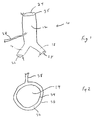
- Fig. 1 shows a perspective view of one embodiment of the present invention.
- the device 10 comprises a tubular body 12 having a central lumen 14 .
- the tubular body 12 is bifurcated at one end into tubular iliac limbs 16 , 18 .
- the central lumen 14 is open at a distal end 24 of the device 10 and is in communication with lumens within the iliac limbs 16 , 18 . which are open at their proximal ends 26 , 28 .
- the device 10 as described thus far is similar structurally to many prior art AAA prostheses although such devices normally also contain a stent.
- the entire structure is distinguished by being double-walled so that an inflating fluid can be injected between the walls.
- the walls of the main body 12 form an annular structure with an inflation space 32 between an inner wall 34 and an outer wall 36 .
- the inner wall 34 and the outer wall 36 show a connection 35 only at the proximal and distal ends of the device 10 (also marked by " ⁇ " in Fig. 1).
- the inflation space 32 is filled by an inflation fluid which is delivered through an inflation conduit 38.
- a preferred embodiment has the inflation conduit 38 removably attached through a valve mechanism (not shown) that allows the conduit 38 to be detached and/or reattached without leakage of the inflation fluid from either the inflation space 32 or the inflation conduit 38 .
- the inflation fluid can be as simple as saline, although a preferred inflation fluid is a gel or a liquid that forms a gel or even hardens after injection to render the device 10 permanently expanded.
- a preferred inflation fluid is a gel or a liquid that forms a gel or even hardens after injection to render the device 10 permanently expanded.
- a wide range of gelling, hardening or polymerizable liquids are available and are well known to those of skill in the art.
- Various silicone rubbers, urethanes or other similar organic elastomers can be used although an ideal inflation fluid should be water because it is miscible and completely non-toxic.
- Various aqueous acrylamide monomer and similar solutions work well in the current invention because they polymerize in situ to produce strong and essentially non-toxic gels. However, the aqueous monomers, themselves, can be toxic.
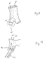
- Fig. 3 shows a perspective view of a portion of the main body 12 of a device having a plurality of longitudinal connections 35 (in phantom) that divide the inflation space 32 into a plurality of longitudinal compartments 42 .
- Fig. 4 is a cross-section of a portion of the device of Fig. 3 and shows that the connection 35 (the regions where the inner wall 34 is connected or fused to the outer wall 36 ) can be made relatively broad.
- microcapillaries can penetrate these regions so that improved healing can occur and an intima can develop within the lumen 14 of the device 10. This is probably most important near the proximal and distal ends of the device which will be in contact with relatively healthy vessel walls from which such capillaries can grow. In the more central portions of the device 10 (the parts actually bridging the aneurysm) it is likely that thrombus will exist between the aneurysm walls and the device 10 , thereby blocking infiltration of capillaries.
- proximal and distal healing is important not only because it supports the formation of intima (which helps prevent thrombus formation) but also because the healing response firmly anchors the ends of the device 10 and prevents shifting thereof. Many prior art devices are forced to provide cumbersome anchoring barbs to prevent device movement.
- connections 35 are functional and may be advantageous.
- the connections 35 can comprise an elongated circumferentially arranged region as shown in Fig. 5.
- Fig. 6 shows a close up view of a portion of the surface of a version of the device 10 with a plurality of punctate connections 35' with various shapes for each individual region (e.g., rectangular or round).
- the punctate connections 35' can be arranged in a variety of patterns. As mentioned above, arrangement of the connections 35 to subdivide the inflation space 32 into longitudinal compartments provides a device having certain physical properties.
- Fig. 7 shows a perspective view of a device having connections 35 helically arranged.
- connection 35 can spiral the entire length of the main body 12 or a plurality of connections 35 can be spirally arranged. This arrangement of connections 35 tends to produce a device 10 that is more flexible laterally (side to side) than the alternative embodiment having longitudinally oriented connections 35. It should be clear to one of skill in the art that the connections 35 that partition the inflation space 32 cannot continue from end to end of the device 10 because inflation fluid would be unable to flow from the inflation conduit 38 into all of the compartments 42. Rather, there must be interruptions in the connections 35 to allow inflation of all the compartments 42.
- Fig. 8 shows a perspective version of a fourth embodiment of the present invention wherein the inflation space 32 is divided into a plurality of longitudinal compartments 42 by connections 35 between the inner 34 and outer 36 walls. Careful inspection will show that some of the compartments 42' are completely cut off from the inflation space 32. These compartments are in communication with the outside milieu through apertures 44.
- the purpose of the apertures 44 and the cut off compartments 42' is to permit the insertion of stiffening devices 46 after the device 10 has been inserted and inflated. This process can be likened to the insertion of fiberglass rods into pockets in a backpacking tent. This allows a backpacking tent to be compressed to a minimal size for transit. After the tent is unfolded, the rods are inserted to hold the tent in an open expanded state.
- the device 10 can be expanded by an external force, e . g ., expanded by a separate balloon, and the stiffening devices 46 inserted.
- Fig. 9 shows the stiffening devices 46 partially inserted (shown in phantom).
- the stiffening devices 46 for all practical purposes behave like a stent. However, as noted above, inclusion of a stent in a graft significantly increases the profile of the graft in its compressed state. With the current invention the graft lacks a permanent stent so that it can be maximally compressed.
- the device 10 is properly placed in an aneurysm, it is inflated to its full size by means of inflation fluid injected through the inflation conduit 38 (or otherwise expanded). Then the resilient stiffening devices 46 are inserted into the compartments 42' to provide improved strength and spring to the expanded device.
- the final physical properties of the expanded device are a combination between the properties of the inflation fluid (if used) and the stiffening devices 46.
- the illustrated example shows longitudinally oriented stiffening devices 46, but other orientations such as helical are possible.
- the compressed device 10 is inserted into the aneurysm e.g., by means of a catheter threaded through an iliac artery.
- the device 10 resides in the tip of the catheter, and a pre-attached inflation conduit 38 can advantageously lead back though the catheter and be available at the entry site where the catheter is inserted into the patient.
- the catheter tip is located in the AAA, the catheter is manipulated to release the compressed device 10 .
- the catheter can be slightly backed out to leave the AAA free for expansion of the device 10.
- Inflation fluid is pumped into the device 10 through the inflation conduit 38 thereby filling the inflation space 32 and causing the device 10 to assume its expanded shape.
- the device can be pulled slightly toward the iliac artery through which the catheter was inserted either by means of the conduit 38 or a guide wire. This causes the proximal end (in terms of the entry site) of the iliac limb 16 to come into contact with the walls of the iliac artery below the aneurysm.
- the iliac opening 26 is sealed to the wall of and becomes continuous with the iliac artery to allow blood flow therethrough.
- the contralateral limb 18 finds its way into the contralateral iliac artery and also becomes sealed into place.
- the inflation conduit 38 is preferably detached and withdrawn through the catheter. If a "hardening" inflation fluid is employed, the conduit 38 can advantageously be detached after hardening occurs thus obviating the need for valves to avoid fluid leakage.
- the stiffening devices 46 can be advanced, for example, from the insertion catheter by methods known to those of skill in the art. They are threaded through the apertures 44 to extend into the main body 12 where they add a centrifugal force that aids in sealing the wall around the distal opening 24 into contact with the aorta wall. It is also possible to configure the device 10 so that the stiffening devices 46 can be passed posteriorly from a more anterior region of the patient to enter the device through apertures 44 placed near the distal opening 24 . An advantage of this alternative approach is that the stiffening devices 46 can more readily be extended into both iliac limbs 16 , 18 . However, this approach does involve using an additional incision and entry point. Again, stiffening devices 46 can be inserted into a device 10 expanded by alternative expansion means as opposed to inflation.
- Each wall 34, 36 of the main body 12 can advantageously be fabricated by extrusion followed by expansion.
- the outer wall 36 component is then placed over the inner wall 34 component, e.g., on a mandrel.
- the connections 35 can be attained by several methods.
- a preferred method is to directly laminate the walls together by applying heat and pressure. This method is especially useful for production of connections 35 intended for promoting penetration of microcapillaries since lamination substantially leaves the ePTFE microstructure intact.
- any of a number of adhesives can be used to connect the PTFE layers.
- Thermoplastic materials such as polyethylene can be used since these materials when heated between the ePTFE layers will melt and interpenetrate the porous ePTFE to "glue" the layers together.
- the iliac limbs 16 , 18 can be formed as separate tubular extrudates and then glued or stitched to the main body 12. Generally a separate bifurcated inner structure and outer structure will be made, and then placed one over the other for the adhesion or lamination process that forms the connections 35. Alternately the bifurcation can be formed as a unitary structure by deforming the main body tubular extrudate over a special mandrel that has a bifurcation (e.g., two legs at one end rather like a human torso with legs). Essentially, the tubular extrudate is radially expanded to encompass both legs of the bifurcation. Then the material between the legs is laminated and then cut away leaving the legs of the mandrel surrounded by ePTFE with seams on the inner leg surfaces where they face each other.
Claims (9)
- Dispositif prosthétique (10) pour réparation endovasculaire d'un anévrisme comprenant :un premier élément tubulaire en polytétrafluoroéthylène expansé ;un second élément tubulaire en polytétrafluoroéthylène expansé coaxial audit premier élément tubulaire et d'un diamètre plus grand de sorte qu'une structure annulaire avec un espace (32) de gonflage soit formée entre les parois interne et externe ainsi formées du dispositif, lesdits premier et second éléments tubulaires étant fixés de manière étanche aux extrémités proximale et distale pour délimiter l'espace de gonflage annulaire ;des moyens formant un orifice pour injection d'un fluide de gonflage dans l'espace entre lesdits éléments tubulaires ; etdes connexions (35) entre les parois interne et externe qui définissent au moins un compartiment allongé de l'espace de gonflage, ledit compartiment s'étendant sur la longueur de l'espace de gonflage.
- Dispositif prosthétique selon la revendication 1, dans lequel lesdits premier et second éléments tubulaires sont bifurqués en branches iliaques tubulaires (16, 18) au niveau de ladite extrémité terminale.
- Dispositif prosthétique selon la revendication 1 ou 2, dans lequel lesdits moyens formant un orifice incluent une conduite (38) de gonflage et un mécanisme de vanne, la conduite de gonflage étant fixée de manière amovible auxdits membres tubulaires.
- Dispositif prosthétique selon la revendication 1, 2 ou 3, comprenant en outre une pluralité de points (35) de contact traversant l'espace, lesdits points de contact étant formés par le fait que ledit premier élément tubulaire est laminé directement sur ledit second élément tubulaire.
- Dispositif prosthétique selon la revendication 4, dans lequel lesdits points de contact sont arrangés longitudinalement.
- Dispositif prosthétique selon la revendication 4, dans lequel lesdits points de contact sont arrangés en circonférence.
- Dispositif prosthétique selon la revendication 4, dans lequel les points de contact sont arrangés en hélice.
- Dispositif prosthétique selon la revendication 5, dans lequel les points de contact créent une pluralité de compartiments (42) orientés longitudinalement placés entre ledit premier élément tubulaire et ledit second élément tubulaire et séparés de l'espace formé par une pluralité de laminations entre ledit premier élément tubulaire et ledit second élément tubulaire ; et
une pluralité d'éléments rigidifiants (46) insérés dans lesdites chambres après que le fluide de gonflage a été injecté dans l'espace. - Dispositif prosthétique selon la revendication 1 et comprenant :une pluralité de chambres (42) placées entre ledit premier membre tubulaire et ledit second membre tubulaire et formées dans l'espace par une pluralité de laminations entre ledit premier élément tubulaire et ledit second élément tubulaire, et les chambres ayant une taille et une structure pour l'insertion d'éléments rigidifiants (46) après que ledit dispositif a été placé dans un anévrisme.
Applications Claiming Priority (3)
| Application Number | Priority Date | Filing Date | Title |
|---|---|---|---|
| US09/401,436 US6312462B1 (en) | 1999-09-22 | 1999-09-22 | Prosthesis for abdominal aortic aneurysm repair |
| US401436 | 1999-09-22 | ||
| PCT/US2000/026126 WO2001021107A1 (fr) | 1999-09-22 | 2000-09-21 | Prothese destinee a la reparation d'un anevrisme de l'aorte abdominale |
Publications (3)
| Publication Number | Publication Date |
|---|---|
| EP1214020A1 EP1214020A1 (fr) | 2002-06-19 |
| EP1214020B1 true EP1214020B1 (fr) | 2005-03-23 |
| EP1214020B2 EP1214020B2 (fr) | 2010-02-17 |
Family
ID=23587755
Family Applications (1)
| Application Number | Title | Priority Date | Filing Date |
|---|---|---|---|
| EP00965353A Expired - Lifetime EP1214020B2 (fr) | 1999-09-22 | 2000-09-21 | Prothese destinee a la reparation d'un anevrisme de l'aorte abdominale |
Country Status (8)
| Country | Link |
|---|---|
| US (1) | US6312462B1 (fr) |
| EP (1) | EP1214020B2 (fr) |
| JP (1) | JP4204229B2 (fr) |
| AT (1) | ATE291394T1 (fr) |
| CA (1) | CA2383428A1 (fr) |
| DE (1) | DE60018945T3 (fr) |
| ES (1) | ES2239040T5 (fr) |
| WO (1) | WO2001021107A1 (fr) |
Cited By (13)
| Publication number | Priority date | Publication date | Assignee | Title |
|---|---|---|---|---|
| US7857845B2 (en) | 2005-02-10 | 2010-12-28 | Sorin Biomedica Cardio S.R.L. | Cardiac-valve prosthesis |
| US8109996B2 (en) | 2004-03-03 | 2012-02-07 | Sorin Biomedica Cardio, S.R.L. | Minimally-invasive cardiac-valve prosthesis |
| US8118856B2 (en) | 2009-07-27 | 2012-02-21 | Endologix, Inc. | Stent graft |
| US8512397B2 (en) | 2009-04-27 | 2013-08-20 | Sorin Group Italia S.R.L. | Prosthetic vascular conduit |
| US8685084B2 (en) | 2011-12-29 | 2014-04-01 | Sorin Group Italia S.R.L. | Prosthetic vascular conduit and assembly method |
| US8808369B2 (en) | 2009-10-05 | 2014-08-19 | Mayo Foundation For Medical Education And Research | Minimally invasive aortic valve replacement |
| US8834563B2 (en) | 2008-12-23 | 2014-09-16 | Sorin Group Italia S.R.L. | Expandable prosthetic valve having anchoring appendages |
| US8840661B2 (en) | 2008-05-16 | 2014-09-23 | Sorin Group Italia S.R.L. | Atraumatic prosthetic heart valve prosthesis |
| US9161836B2 (en) | 2011-02-14 | 2015-10-20 | Sorin Group Italia S.R.L. | Sutureless anchoring device for cardiac valve prostheses |
| US9248017B2 (en) | 2010-05-21 | 2016-02-02 | Sorin Group Italia S.R.L. | Support device for valve prostheses and corresponding kit |
| US9289289B2 (en) | 2011-02-14 | 2016-03-22 | Sorin Group Italia S.R.L. | Sutureless anchoring device for cardiac valve prostheses |
| US10966823B2 (en) | 2007-10-12 | 2021-04-06 | Sorin Group Italia S.R.L. | Expandable valve prosthesis with sealing mechanism |
| US11504231B2 (en) | 2018-05-23 | 2022-11-22 | Corcym S.R.L. | Cardiac valve prosthesis |
Families Citing this family (138)
| Publication number | Priority date | Publication date | Assignee | Title |
|---|---|---|---|---|
| US5609627A (en) * | 1994-02-09 | 1997-03-11 | Boston Scientific Technology, Inc. | Method for delivering a bifurcated endoluminal prosthesis |
| US6051020A (en) | 1994-02-09 | 2000-04-18 | Boston Scientific Technology, Inc. | Bifurcated endoluminal prosthesis |
| US5871537A (en) * | 1996-02-13 | 1999-02-16 | Scimed Life Systems, Inc. | Endovascular apparatus |
| US6395019B2 (en) | 1998-02-09 | 2002-05-28 | Trivascular, Inc. | Endovascular graft |
| US6042597A (en) | 1998-10-23 | 2000-03-28 | Scimed Life Systems, Inc. | Helical stent design |
| GB9904722D0 (en) * | 1999-03-03 | 1999-04-21 | Murch Clifford R | A tubular intraluminal graft |
| WO2004100841A1 (fr) | 1999-08-18 | 2004-11-25 | Intrinsic Therapeutics, Inc. | Dispositifs et procedes de densification du noyau du disque vertebral |
| US7972337B2 (en) | 2005-12-28 | 2011-07-05 | Intrinsic Therapeutics, Inc. | Devices and methods for bone anchoring |
| US6936072B2 (en) | 1999-08-18 | 2005-08-30 | Intrinsic Therapeutics, Inc. | Encapsulated intervertebral disc prosthesis and methods of manufacture |
| US7220281B2 (en) | 1999-08-18 | 2007-05-22 | Intrinsic Therapeutics, Inc. | Implant for reinforcing and annulus fibrosis |
| US7553329B2 (en) | 1999-08-18 | 2009-06-30 | Intrinsic Therapeutics, Inc. | Stabilized intervertebral disc barrier |
| US7717961B2 (en) | 1999-08-18 | 2010-05-18 | Intrinsic Therapeutics, Inc. | Apparatus delivery in an intervertebral disc |
| JP4247519B2 (ja) | 1999-08-18 | 2009-04-02 | イントリンジック セラピューティックス インコーポレイテッド | 髄核オーグメンテーションおよび保定のための装置および方法 |
| US8323341B2 (en) | 2007-09-07 | 2012-12-04 | Intrinsic Therapeutics, Inc. | Impaction grafting for vertebral fusion |
| WO2009033100A1 (fr) | 2007-09-07 | 2009-03-12 | Intrinsic Therapeutics, Inc. | Systèmes d'ancrage osseux |
| US7998213B2 (en) | 1999-08-18 | 2011-08-16 | Intrinsic Therapeutics, Inc. | Intervertebral disc herniation repair |
| ATE255860T1 (de) * | 2000-03-03 | 2003-12-15 | Cook Inc | Endovaskuläre vorrichtung mit stent |
| US6733521B2 (en) | 2001-04-11 | 2004-05-11 | Trivascular, Inc. | Delivery system and method for endovascular graft |
| US6761733B2 (en) | 2001-04-11 | 2004-07-13 | Trivascular, Inc. | Delivery system and method for bifurcated endovascular graft |
| GB0114918D0 (en) * | 2001-06-19 | 2001-08-08 | Vortex Innovation Ltd | Devices for repairing aneurysms |
| US7192441B2 (en) * | 2001-10-16 | 2007-03-20 | Scimed Life Systems, Inc. | Aortic artery aneurysm endovascular prosthesis |
| AUPR847201A0 (en) * | 2001-10-26 | 2001-11-15 | Cook Incorporated | Endoluminal graft |
| US20060292206A1 (en) | 2001-11-26 | 2006-12-28 | Kim Steven W | Devices and methods for treatment of vascular aneurysms |
| US7147661B2 (en) * | 2001-12-20 | 2006-12-12 | Boston Scientific Santa Rosa Corp. | Radially expandable stent |
| US7090693B1 (en) * | 2001-12-20 | 2006-08-15 | Boston Scientific Santa Rosa Corp. | Endovascular graft joint and method for manufacture |
| US20100016943A1 (en) | 2001-12-20 | 2010-01-21 | Trivascular2, Inc. | Method of delivering advanced endovascular graft |
| US7125464B2 (en) * | 2001-12-20 | 2006-10-24 | Boston Scientific Santa Rosa Corp. | Method for manufacturing an endovascular graft section |
| US6776604B1 (en) | 2001-12-20 | 2004-08-17 | Trivascular, Inc. | Method and apparatus for shape forming endovascular graft material |
| CA2468951A1 (fr) * | 2001-12-20 | 2003-07-03 | Trivascular, Inc. | Greffon endovasculaire evolue |
| EP1465685B1 (fr) * | 2001-12-20 | 2010-03-17 | TriVascular2, Inc. | Procede et appareil de fabrication d'une section de greffon endocoronaire |
| US8308797B2 (en) | 2002-01-04 | 2012-11-13 | Colibri Heart Valve, LLC | Percutaneously implantable replacement heart valve device and method of making same |
| US20040116997A1 (en) * | 2002-09-20 | 2004-06-17 | Taylor Charles S. | Stent-graft with positioning anchor |
| US20040098096A1 (en) * | 2002-10-22 | 2004-05-20 | The University Of Miami | Endograft device to inhibit endoleak and migration |
| US7481821B2 (en) | 2002-11-12 | 2009-01-27 | Thomas J. Fogarty | Embolization device and a method of using the same |
| US6926735B2 (en) * | 2002-12-23 | 2005-08-09 | Scimed Life Systems, Inc. | Multi-lumen vascular grafts having improved self-sealing properties |
| AU2003299946A1 (en) * | 2002-12-30 | 2004-07-29 | Morsi Hesham | Endovascular balloon graft |
| US20040260382A1 (en) | 2003-02-12 | 2004-12-23 | Fogarty Thomas J. | Intravascular implants and methods of using the same |
| US7025779B2 (en) | 2003-02-26 | 2006-04-11 | Scimed Life Systems, Inc. | Endoluminal device having enhanced affixation characteristics |
| US7150758B2 (en) * | 2003-03-06 | 2006-12-19 | Boston Scientific Santa Rosa Corp. | Kink resistant endovascular graft |
| US20040230289A1 (en) * | 2003-05-15 | 2004-11-18 | Scimed Life Systems, Inc. | Sealable attachment of endovascular stent to graft |
| US7632291B2 (en) | 2003-06-13 | 2009-12-15 | Trivascular2, Inc. | Inflatable implant |
| US20040254628A1 (en) * | 2003-06-13 | 2004-12-16 | Patrice Nazzaro | One-branch stent-graft for bifurcated lumens |
| DK1638485T3 (da) | 2003-06-20 | 2011-05-02 | Intrinsic Therapeutics Inc | Indretning til levering af et implantat gennem en ringformet defekt i en intervertebralskive |
| US20050015110A1 (en) | 2003-07-18 | 2005-01-20 | Fogarty Thomas J. | Embolization device and a method of using the same |
| US7803178B2 (en) | 2004-01-30 | 2010-09-28 | Trivascular, Inc. | Inflatable porous implants and methods for drug delivery |
| US8034096B2 (en) * | 2004-03-31 | 2011-10-11 | Cook Medical Technologies Llc | Stent-graft with graft to graft attachment |
| US8377118B2 (en) | 2004-05-05 | 2013-02-19 | Direct Flow Medical, Inc. | Unstented heart valve with formed in place support structure |
| GB0415152D0 (en) * | 2004-07-06 | 2004-08-11 | Anson Medical Ltd | Interconnected tubular structures |
| US7758626B2 (en) * | 2004-07-20 | 2010-07-20 | Medtronic Vascular, Inc. | Device and method for delivering an endovascular stent-graft having a longitudinally unsupported portion |
| US8048145B2 (en) | 2004-07-22 | 2011-11-01 | Endologix, Inc. | Graft systems having filling structures supported by scaffolds and methods for their use |
| EP1778131B1 (fr) | 2004-07-22 | 2012-01-11 | Nellix, Inc. | Systèmes pour le traitement d'anévrisme endovasculaire |
| JP4583881B2 (ja) * | 2004-11-01 | 2010-11-17 | テルモ株式会社 | 接合方法 |
| US8029563B2 (en) | 2004-11-29 | 2011-10-04 | Gore Enterprise Holdings, Inc. | Implantable devices with reduced needle puncture site leakage |
| US20060222596A1 (en) | 2005-04-01 | 2006-10-05 | Trivascular, Inc. | Non-degradable, low swelling, water soluble radiopaque hydrogel polymer |
| JP5119148B2 (ja) | 2005-06-07 | 2013-01-16 | ダイレクト フロウ メディカル、 インク. | 半径方向の強度が高いステントレス大動脈弁置換 |
| AU2006269419A1 (en) | 2005-07-07 | 2007-01-18 | Nellix, Inc. | Systems and methods for endovascular aneurysm treatment |
| GB0517085D0 (en) | 2005-08-19 | 2005-09-28 | Angiomed Ag | Polymer prosthesis |
| US7790273B2 (en) * | 2006-05-24 | 2010-09-07 | Nellix, Inc. | Material for creating multi-layered films and methods for making the same |
| US7872068B2 (en) | 2006-05-30 | 2011-01-18 | Incept Llc | Materials formable in situ within a medical device |
| US8216297B2 (en) * | 2006-08-14 | 2012-07-10 | Trivascular, Inc. | Dual chamber cuff structure |
| US7544213B2 (en) * | 2006-09-12 | 2009-06-09 | Adams Jason P | Inflatable hernia patch |
| US7935144B2 (en) | 2006-10-19 | 2011-05-03 | Direct Flow Medical, Inc. | Profile reduction of valve implant |
| US8133213B2 (en) | 2006-10-19 | 2012-03-13 | Direct Flow Medical, Inc. | Catheter guidance through a calcified aortic valve |
| US8257431B2 (en) | 2006-11-01 | 2012-09-04 | Boston Scientific Scimed, Inc. | Multi-furcated ePTFE grafts and stent-graft prostheses and methods of making the same |
| US7655034B2 (en) * | 2006-11-14 | 2010-02-02 | Medtronic Vascular, Inc. | Stent-graft with anchoring pins |
| US20080133002A1 (en) * | 2006-12-05 | 2008-06-05 | Daniel Gelbart | Inflatable artificial valve |
| US20080188923A1 (en) * | 2007-02-01 | 2008-08-07 | Jack Fa-De Chu | Endovascular devices to protect aneurysmal wall |
| AU2008224435B2 (en) | 2007-03-15 | 2014-01-09 | Ortho-Space Ltd. | Prosthetic devices and methods for using same |
| US20080228259A1 (en) * | 2007-03-16 | 2008-09-18 | Jack Fa-De Chu | Endovascular devices and methods to protect aneurysmal wall |
| US20080294237A1 (en) * | 2007-04-04 | 2008-11-27 | Jack Fa-De Chu | Inflatable devices and methods to protect aneurysmal wall |
| US20080262590A1 (en) * | 2007-04-19 | 2008-10-23 | Medtronic Vascular, Inc. | Delivery System for Stent-Graft |
| AU2008288796B2 (en) | 2007-08-23 | 2014-03-20 | Dfm, Llc | Cardiovascular prosthetic valve |
| US7976497B2 (en) | 2007-09-25 | 2011-07-12 | Polyzen Inc. | Multi-layer film welded articulated balloon |
| US8226701B2 (en) | 2007-09-26 | 2012-07-24 | Trivascular, Inc. | Stent and delivery system for deployment thereof |
| US8066755B2 (en) | 2007-09-26 | 2011-11-29 | Trivascular, Inc. | System and method of pivoted stent deployment |
| US8663309B2 (en) | 2007-09-26 | 2014-03-04 | Trivascular, Inc. | Asymmetric stent apparatus and method |
| CN101917929A (zh) | 2007-10-04 | 2010-12-15 | 特里瓦斯库拉尔公司 | 用于低型面经皮递送的模块化脉管移植物 |
| US20090105811A1 (en) * | 2007-10-18 | 2009-04-23 | Medtronic, Inc. | Intravascular Devices for Cell-Based Therapies |
| US8083789B2 (en) | 2007-11-16 | 2011-12-27 | Trivascular, Inc. | Securement assembly and method for expandable endovascular device |
| US8328861B2 (en) | 2007-11-16 | 2012-12-11 | Trivascular, Inc. | Delivery system and method for bifurcated graft |
| US7862538B2 (en) * | 2008-02-04 | 2011-01-04 | Incept Llc | Surgical delivery system for medical sealant |
| CA2714570A1 (fr) * | 2008-02-13 | 2009-08-20 | Nellix, Inc. | Endocadre de greffe ayant des caracteristiques variables axialement |
| CA2721950A1 (fr) | 2008-04-25 | 2009-10-29 | Nellix, Inc. | Systeme de mise en place d'endoprothese vasculaire |
| AU2009256084A1 (en) | 2008-06-04 | 2009-12-10 | Nellix, Inc. | Sealing apparatus and methods of use |
| JP2011522614A (ja) | 2008-06-04 | 2011-08-04 | ネリックス・インコーポレーテッド | ドッキング装置および使用方法 |
| US20100010518A1 (en) * | 2008-07-09 | 2010-01-14 | Joshua Stopek | Anastomosis Sheath And Method Of Use |
| US8413661B2 (en) | 2008-08-14 | 2013-04-09 | Ethicon, Inc. | Methods and devices for treatment of obstructive sleep apnea |
| US20100100170A1 (en) | 2008-10-22 | 2010-04-22 | Boston Scientific Scimed, Inc. | Shape memory tubular stent with grooves |
| US8800567B2 (en) | 2008-12-01 | 2014-08-12 | Ethicon, Inc. | Implant systems and methods for treating obstructive sleep apnea |
| US20130268062A1 (en) | 2012-04-05 | 2013-10-10 | Zeus Industrial Products, Inc. | Composite prosthetic devices |
| US8371308B2 (en) | 2009-02-17 | 2013-02-12 | Ethicon, Inc. | Magnetic implants and methods for treating an oropharyngeal condition |
| US8307831B2 (en) | 2009-03-16 | 2012-11-13 | Ethicon, Inc. | Implant systems and methods for treating obstructive sleep apnea |
| US10772717B2 (en) | 2009-05-01 | 2020-09-15 | Endologix, Inc. | Percutaneous method and device to treat dissections |
| JP2012525239A (ja) | 2009-05-01 | 2012-10-22 | エンドロジックス、インク | 解離を治療するための経皮的な方法および装置(優先権情報および参照による組み入れ) |
| JP2013501539A (ja) | 2009-08-07 | 2013-01-17 | ゼウス インダストリアル プロダクツ インコーポレイテッド | 静電紡糸繊維層を備える補綴具及びその製造方法 |
| US9877862B2 (en) | 2009-10-29 | 2018-01-30 | Ethicon, Inc. | Tongue suspension system with hyoid-extender for treating obstructive sleep apnea |
| US9326886B2 (en) | 2009-10-29 | 2016-05-03 | Ethicon, Inc. | Fluid filled implants for treating obstructive sleep apnea |
| US9974683B2 (en) | 2009-10-30 | 2018-05-22 | Ethicon, Inc. | Flexible implants having internal volume shifting capabilities for treating obstructive sleep apnea |
| US8632488B2 (en) | 2009-12-15 | 2014-01-21 | Ethicon, Inc. | Fluid filled implants for treating medical conditions |
| US20110276078A1 (en) | 2009-12-30 | 2011-11-10 | Nellix, Inc. | Filling structure for a graft system and methods of use |
| FR2955480B1 (fr) * | 2010-01-26 | 2012-01-06 | Christian Choux | Dispositif d'osteosynthese de la paroi thoracique |
| SG186837A1 (en) | 2010-03-01 | 2013-02-28 | Colibri Heart Valve Llc | Percutaneously deliverable heart valve and methods associated therewith |
| US8454682B2 (en) | 2010-04-13 | 2013-06-04 | Medtronic Vascular, Inc. | Anchor pin stent-graft delivery system |
| US8696738B2 (en) | 2010-05-20 | 2014-04-15 | Maquet Cardiovascular Llc | Composite prosthesis with external polymeric support structure and methods of manufacturing the same |
| AU2011276503B2 (en) | 2010-06-28 | 2015-09-17 | Colibri Heart Value LLC | Method and apparatus for the endoluminal delivery of intravascular devices |
| US8961501B2 (en) | 2010-09-17 | 2015-02-24 | Incept, Llc | Method for applying flowable hydrogels to a cornea |
| WO2012068298A1 (fr) | 2010-11-17 | 2012-05-24 | Endologix, Inc. | Dispositifs et procédés de traitement de dissections vasculaires |
| SG10201601962WA (en) | 2010-12-14 | 2016-04-28 | Colibri Heart Valve Llc | Percutaneously deliverable heart valve including folded membrane cusps with integral leaflets |
| US8801768B2 (en) | 2011-01-21 | 2014-08-12 | Endologix, Inc. | Graft systems having semi-permeable filling structures and methods for their use |
| JP5976777B2 (ja) | 2011-04-06 | 2016-08-24 | エンドーロジックス インコーポレイテッド | 血管内動脈瘤治療のための方法およびシステム |
| US8905033B2 (en) | 2011-09-28 | 2014-12-09 | Ethicon, Inc. | Modular tissue securement systems |
| WO2013057566A2 (fr) | 2011-10-18 | 2013-04-25 | Ortho-Space Ltd. | Dispositifs prothétiques et procédés d'utilisation associés |
| US9161855B2 (en) | 2011-10-24 | 2015-10-20 | Ethicon, Inc. | Tissue supporting device and method |
| US8973582B2 (en) | 2011-11-30 | 2015-03-10 | Ethicon, Inc. | Tongue suspension device and method |
| US10470760B2 (en) | 2011-12-08 | 2019-11-12 | Ethicon, Inc. | Modified tissue securement fibers |
| US8992595B2 (en) | 2012-04-04 | 2015-03-31 | Trivascular, Inc. | Durable stent graft with tapered struts and stable delivery methods and devices |
| US9498363B2 (en) | 2012-04-06 | 2016-11-22 | Trivascular, Inc. | Delivery catheter for endovascular device |
| US9173766B2 (en) | 2012-06-01 | 2015-11-03 | Ethicon, Inc. | Systems and methods to treat upper pharyngeal airway of obstructive sleep apnea patients |
| US9289536B2 (en) | 2013-03-14 | 2016-03-22 | Endologix, Inc. | Method for forming materials in situ within a medical device |
| US9814560B2 (en) | 2013-12-05 | 2017-11-14 | W. L. Gore & Associates, Inc. | Tapered implantable device and methods for making such devices |
| CN113648464B (zh) * | 2014-03-07 | 2022-12-30 | 恩朵罗杰克斯有限责任公司 | 形成水凝胶和用于形成水凝胶的材料 |
| IL250181B2 (en) | 2014-07-20 | 2024-04-01 | Bruckheimer Elchanan | Pulmonary artery graft |
| BR112017025950A2 (pt) | 2015-06-05 | 2018-08-14 | W. L. Gore & Associates, Inc. | ?prótese implantável de baixo sangramento com um afunilador? |
| WO2017046647A1 (fr) | 2015-09-18 | 2017-03-23 | Ortho-Space Ltd. | Écarteurs sous-acromiaux fixés de manière intramédullaire |
| US11771434B2 (en) | 2016-09-28 | 2023-10-03 | Restore Medical Ltd. | Artery medical apparatus and methods of use thereof |
| EP3573806A4 (fr) | 2017-01-30 | 2019-12-11 | Ortho-Space Ltd. | Machine de traitement et procédés de traitement d'articles moulés par immersion |
| US11883273B2 (en) * | 2017-04-28 | 2024-01-30 | Regents Of The University Of Minnesota | Compliant aortic stent grafts and related systems and methods |
| WO2018225059A1 (fr) | 2017-06-05 | 2018-12-13 | Restore Medical Ltd | Appareil de type endoprothèse à longueur fixe à double paroi et ses procédés d'utilisation |
| EP3634528B1 (fr) | 2017-06-07 | 2023-06-07 | Shifamed Holdings, LLC | Dispositifs de déplacement de fluide intravasculaire, systèmes et procédés d'utilisation |
| WO2019051476A1 (fr) | 2017-09-11 | 2019-03-14 | Incubar, LLC | Dispositif d'étanchéité destiné à être utilisé comme implant vasculaire de conduit pour réduire l'endofuite |
| CN111556763B (zh) | 2017-11-13 | 2023-09-01 | 施菲姆德控股有限责任公司 | 血管内流体运动装置、系统 |
| US10893929B2 (en) * | 2018-01-10 | 2021-01-19 | Cook Medical Technologies Llc | Vascular graft with compartments for compliance matching |
| US10517713B2 (en) * | 2018-01-10 | 2019-12-31 | Cook Medical Technologies Llc | Vascular graft with helical flow compliance compartments |
| JP7410034B2 (ja) | 2018-02-01 | 2024-01-09 | シファメド・ホールディングス・エルエルシー | 血管内血液ポンプならびに使用および製造の方法 |
| JP2022525788A (ja) | 2019-03-20 | 2022-05-19 | インキュベート メディカル テクノロジーズ、 エルエルシー | 大動脈解離インプラント |
| WO2021016372A1 (fr) | 2019-07-22 | 2021-01-28 | Shifamed Holdings, Llc | Pompes à sang intravasculaires à entretoises et procédés d'utilisation et de fabrication |
| EP4034192A4 (fr) | 2019-09-25 | 2023-11-29 | Shifamed Holdings, LLC | Dispositifs et systèmes de pompes à sang intravasculaires et leurs procédés d'utilisation et de commande |
| US20230226343A1 (en) * | 2020-05-12 | 2023-07-20 | Shifamed Holdings, Llc | Inflatable medical devices, methods of manufacture and use |
Family Cites Families (27)
| Publication number | Priority date | Publication date | Assignee | Title |
|---|---|---|---|---|
| US3435824A (en) | 1966-10-27 | 1969-04-01 | Herminio Gamponia | Surgical apparatus and related process |
| US5275622A (en) | 1983-12-09 | 1994-01-04 | Harrison Medical Technologies, Inc. | Endovascular grafting apparatus, system and method and devices for use therewith |
| US5328471A (en) | 1990-02-26 | 1994-07-12 | Endoluminal Therapeutics, Inc. | Method and apparatus for treatment of focal disease in hollow tubular organs and other tissue lumens |
| US5100429A (en) | 1989-04-28 | 1992-03-31 | C. R. Bard, Inc. | Endovascular stent and delivery system |
| US5108370A (en) | 1989-10-03 | 1992-04-28 | Paul Walinsky | Perfusion balloon catheter |
| GB8927282D0 (en) * | 1989-12-01 | 1990-01-31 | Univ Strathclyde | Vascular surgical devices |
| US5360443A (en) | 1990-06-11 | 1994-11-01 | Barone Hector D | Aortic graft for repairing an abdominal aortic aneurysm |
| US5156620A (en) * | 1991-02-04 | 1992-10-20 | Pigott John P | Intraluminal graft/stent and balloon catheter for insertion thereof |
| CA2065634C (fr) | 1991-04-11 | 1997-06-03 | Alec A. Piplani | Greffon endovasculaire ayant une bifurcation et appareil et methode servant a le deployer |
| EP1101457A3 (fr) | 1991-09-16 | 2001-11-07 | Atrium Medical Corporation | Dispositif implantable, à lumière primaire, à porosité régulée |
| US5151105A (en) * | 1991-10-07 | 1992-09-29 | Kwan Gett Clifford | Collapsible vessel sleeve implant |
| WO1995013033A1 (fr) * | 1993-11-08 | 1995-05-18 | Lazarus Harrison M | Greffon vasculaire intraluminal et procede |
| US5613948A (en) | 1993-11-12 | 1997-03-25 | Cordis Corporation | Annular perfusion balloon catheter |
| US5441485A (en) | 1994-02-24 | 1995-08-15 | Peters; Michael J. | Bladder catheter |
| US5423851A (en) * | 1994-03-06 | 1995-06-13 | Samuels; Shaun L. W. | Method and apparatus for affixing an endoluminal device to the walls of tubular structures within the body |
| US6045496A (en) * | 1994-04-15 | 2000-04-04 | Allegheny-Singer Research Institute | Occluder device and method of making |
| US5545135A (en) | 1994-10-31 | 1996-08-13 | Boston Scientific Corporation | Perfusion balloon stent |
| US5534024A (en) † | 1994-11-04 | 1996-07-09 | Aeroquip Corporation | Intraluminal stenting graft |
| US5554180A (en) * | 1995-07-07 | 1996-09-10 | Aeroquip Corporation | Intraluminal stenting graft |
| US5785679A (en) | 1995-07-19 | 1998-07-28 | Endotex Interventional Systems, Inc. | Methods and apparatus for treating aneurysms and arterio-venous fistulas |
| US5769882A (en) | 1995-09-08 | 1998-06-23 | Medtronic, Inc. | Methods and apparatus for conformably sealing prostheses within body lumens |
| US5665117A (en) | 1995-11-27 | 1997-09-09 | Rhodes; Valentine J. | Endovascular prosthesis with improved sealing means for aneurysmal arterial disease and method of use |
| US5800512A (en) * | 1996-01-22 | 1998-09-01 | Meadox Medicals, Inc. | PTFE vascular graft |
| US5871537A (en) | 1996-02-13 | 1999-02-16 | Scimed Life Systems, Inc. | Endovascular apparatus |
| CA2197375C (fr) * | 1996-02-15 | 2003-05-06 | Yasuhiro Okuda | Vesseau sanguin artificiel |
| US6395019B2 (en) | 1998-02-09 | 2002-05-28 | Trivascular, Inc. | Endovascular graft |
| WO2000001439A1 (fr) | 1998-07-01 | 2000-01-13 | University Of Pittsburgh Of The Commonwealth System Of Higher Education | Applicateur non occlusif de fermeture coaxiale d'un vaisseau |
-
1999
- 1999-09-22 US US09/401,436 patent/US6312462B1/en not_active Expired - Lifetime
-
2000
- 2000-09-21 WO PCT/US2000/026126 patent/WO2001021107A1/fr active IP Right Grant
- 2000-09-21 AT AT00965353T patent/ATE291394T1/de not_active IP Right Cessation
- 2000-09-21 EP EP00965353A patent/EP1214020B2/fr not_active Expired - Lifetime
- 2000-09-21 DE DE60018945T patent/DE60018945T3/de not_active Expired - Lifetime
- 2000-09-21 ES ES00965353T patent/ES2239040T5/es not_active Expired - Lifetime
- 2000-09-21 JP JP2001524537A patent/JP4204229B2/ja not_active Expired - Fee Related
- 2000-09-21 CA CA002383428A patent/CA2383428A1/fr not_active Abandoned
Cited By (25)
| Publication number | Priority date | Publication date | Assignee | Title |
|---|---|---|---|---|
| US8535373B2 (en) | 2004-03-03 | 2013-09-17 | Sorin Group Italia S.R.L. | Minimally-invasive cardiac-valve prosthesis |
| US8109996B2 (en) | 2004-03-03 | 2012-02-07 | Sorin Biomedica Cardio, S.R.L. | Minimally-invasive cardiac-valve prosthesis |
| US9867695B2 (en) | 2004-03-03 | 2018-01-16 | Sorin Group Italia S.R.L. | Minimally-invasive cardiac-valve prosthesis |
| US8539662B2 (en) | 2005-02-10 | 2013-09-24 | Sorin Group Italia S.R.L. | Cardiac-valve prosthesis |
| US9486313B2 (en) | 2005-02-10 | 2016-11-08 | Sorin Group Italia S.R.L. | Cardiac valve prosthesis |
| US8540768B2 (en) | 2005-02-10 | 2013-09-24 | Sorin Group Italia S.R.L. | Cardiac valve prosthesis |
| US7857845B2 (en) | 2005-02-10 | 2010-12-28 | Sorin Biomedica Cardio S.R.L. | Cardiac-valve prosthesis |
| US8920492B2 (en) | 2005-02-10 | 2014-12-30 | Sorin Group Italia S.R.L. | Cardiac valve prosthesis |
| US9895223B2 (en) | 2005-02-10 | 2018-02-20 | Sorin Group Italia S.R.L. | Cardiac valve prosthesis |
| US10966823B2 (en) | 2007-10-12 | 2021-04-06 | Sorin Group Italia S.R.L. | Expandable valve prosthesis with sealing mechanism |
| US8840661B2 (en) | 2008-05-16 | 2014-09-23 | Sorin Group Italia S.R.L. | Atraumatic prosthetic heart valve prosthesis |
| US10098733B2 (en) | 2008-12-23 | 2018-10-16 | Sorin Group Italia S.R.L. | Expandable prosthetic valve having anchoring appendages |
| US8834563B2 (en) | 2008-12-23 | 2014-09-16 | Sorin Group Italia S.R.L. | Expandable prosthetic valve having anchoring appendages |
| US8512397B2 (en) | 2009-04-27 | 2013-08-20 | Sorin Group Italia S.R.L. | Prosthetic vascular conduit |
| US8821564B2 (en) | 2009-07-27 | 2014-09-02 | Endologix, Inc. | Stent graft |
| US8118856B2 (en) | 2009-07-27 | 2012-02-21 | Endologix, Inc. | Stent graft |
| US9907642B2 (en) | 2009-07-27 | 2018-03-06 | Endologix, Inc. | Stent graft |
| US10874502B2 (en) | 2009-07-27 | 2020-12-29 | Endologix Llc | Stent graft |
| US8808369B2 (en) | 2009-10-05 | 2014-08-19 | Mayo Foundation For Medical Education And Research | Minimally invasive aortic valve replacement |
| US9248017B2 (en) | 2010-05-21 | 2016-02-02 | Sorin Group Italia S.R.L. | Support device for valve prostheses and corresponding kit |
| US9289289B2 (en) | 2011-02-14 | 2016-03-22 | Sorin Group Italia S.R.L. | Sutureless anchoring device for cardiac valve prostheses |
| US9161836B2 (en) | 2011-02-14 | 2015-10-20 | Sorin Group Italia S.R.L. | Sutureless anchoring device for cardiac valve prostheses |
| US9138314B2 (en) | 2011-12-29 | 2015-09-22 | Sorin Group Italia S.R.L. | Prosthetic vascular conduit and assembly method |
| US8685084B2 (en) | 2011-12-29 | 2014-04-01 | Sorin Group Italia S.R.L. | Prosthetic vascular conduit and assembly method |
| US11504231B2 (en) | 2018-05-23 | 2022-11-22 | Corcym S.R.L. | Cardiac valve prosthesis |
Also Published As
| Publication number | Publication date |
|---|---|
| ATE291394T1 (de) | 2005-04-15 |
| WO2001021107A9 (fr) | 2002-10-03 |
| ES2239040T5 (es) | 2010-05-20 |
| EP1214020A1 (fr) | 2002-06-19 |
| ES2239040T3 (es) | 2005-09-16 |
| JP2003509157A (ja) | 2003-03-11 |
| DE60018945T2 (de) | 2006-04-20 |
| EP1214020B2 (fr) | 2010-02-17 |
| DE60018945D1 (de) | 2005-04-28 |
| WO2001021107A1 (fr) | 2001-03-29 |
| JP4204229B2 (ja) | 2009-01-07 |
| DE60018945T3 (de) | 2010-08-12 |
| CA2383428A1 (fr) | 2001-03-29 |
| US6312462B1 (en) | 2001-11-06 |
Similar Documents
| Publication | Publication Date | Title |
|---|---|---|
| EP1214020B1 (fr) | Prothese destinee a la reparation d'un anevrisme de l'aorte abdominale | |
| US20210093473A1 (en) | System and methods for endovascular aneurysm treatment | |
| US9408688B2 (en) | Devices and methods for treatment of abdominal aortic aneurysm | |
| CA2528717C (fr) | Prothese comprenant un stent dont les deux extremites sont effilees | |
| ES2464783T3 (es) | Prótesis bifurcada resistente a la torsión | |
| US20150265394A1 (en) | Devices and methods for treatment of abdominal aortic aneurysms | |
| JP2003230579A (ja) | 胸動脈瘤治療用のプロテーゼおよびシステム | |
| KR20050083807A (ko) | 내부누설 및 이동을 억제하는 내부이식 장치 | |
| JP2003245292A (ja) | 両側延伸用プロテーゼおよび配給方法 | |
| ES2539505T3 (es) | Dispositivo intraluminal expansible | |
| KR20020012574A (ko) | 증가된 유연성을 갖는 스텐트-이식편 | |
| CA2571282C (fr) | Prothese comprenant une endoprothese spiralee et methode d'utilisation |
Legal Events
| Date | Code | Title | Description |
|---|---|---|---|
| PUAI | Public reference made under article 153(3) epc to a published international application that has entered the european phase |
Free format text: ORIGINAL CODE: 0009012 |
|
| 17P | Request for examination filed |
Effective date: 20020305 |
|
| AK | Designated contracting states |
Kind code of ref document: A1 Designated state(s): AT BE CH CY DE DK ES FI FR GB GR IE IT LI LU MC NL PT SE |
|
| RIN1 | Information on inventor provided before grant (corrected) |
Inventor name: RENZI, DAVID Inventor name: MCDERMOTT, JOHN, D. Inventor name: BANAS, CHRISTOPHER, E. Inventor name: LAYNE, RICHARD, W. |
|
| RAP1 | Party data changed (applicant data changed or rights of an application transferred) |
Owner name: BARD PERIPHERAL VASCULAR, INC. |
|
| 17Q | First examination report despatched |
Effective date: 20040224 |
|
| GRAP | Despatch of communication of intention to grant a patent |
Free format text: ORIGINAL CODE: EPIDOSNIGR1 |
|
| RAP1 | Party data changed (applicant data changed or rights of an application transferred) |
Owner name: BARD PERIPHREAL VASCULAR, INC. |
|
| RAP1 | Party data changed (applicant data changed or rights of an application transferred) |
Owner name: BARD PERIPHERAL VASCULAR, INC. |
|
| GRAS | Grant fee paid |
Free format text: ORIGINAL CODE: EPIDOSNIGR3 |
|
| GRAA | (expected) grant |
Free format text: ORIGINAL CODE: 0009210 |
|
| AK | Designated contracting states |
Kind code of ref document: B1 Designated state(s): AT BE CH CY DE DK ES FI FR GB GR IE IT LI LU MC NL PT SE |
|
| PG25 | Lapsed in a contracting state [announced via postgrant information from national office to epo] |
Ref country code: CH Free format text: LAPSE BECAUSE OF FAILURE TO SUBMIT A TRANSLATION OF THE DESCRIPTION OR TO PAY THE FEE WITHIN THE PRESCRIBED TIME-LIMIT Effective date: 20050323 Ref country code: AT Free format text: LAPSE BECAUSE OF FAILURE TO SUBMIT A TRANSLATION OF THE DESCRIPTION OR TO PAY THE FEE WITHIN THE PRESCRIBED TIME-LIMIT Effective date: 20050323 Ref country code: FI Free format text: LAPSE BECAUSE OF FAILURE TO SUBMIT A TRANSLATION OF THE DESCRIPTION OR TO PAY THE FEE WITHIN THE PRESCRIBED TIME-LIMIT Effective date: 20050323 Ref country code: LI Free format text: LAPSE BECAUSE OF FAILURE TO SUBMIT A TRANSLATION OF THE DESCRIPTION OR TO PAY THE FEE WITHIN THE PRESCRIBED TIME-LIMIT Effective date: 20050323 |
|
| REG | Reference to a national code |
Ref country code: GB Ref legal event code: FG4D |
|
| REG | Reference to a national code |
Ref country code: CH Ref legal event code: EP |
|
| REG | Reference to a national code |
Ref country code: IE Ref legal event code: FG4D |
|
| REF | Corresponds to: |
Ref document number: 60018945 Country of ref document: DE Date of ref document: 20050428 Kind code of ref document: P |
|
| PG25 | Lapsed in a contracting state [announced via postgrant information from national office to epo] |
Ref country code: GR Free format text: LAPSE BECAUSE OF FAILURE TO SUBMIT A TRANSLATION OF THE DESCRIPTION OR TO PAY THE FEE WITHIN THE PRESCRIBED TIME-LIMIT Effective date: 20050623 Ref country code: DK Free format text: LAPSE BECAUSE OF FAILURE TO SUBMIT A TRANSLATION OF THE DESCRIPTION OR TO PAY THE FEE WITHIN THE PRESCRIBED TIME-LIMIT Effective date: 20050623 |
|
| PG25 | Lapsed in a contracting state [announced via postgrant information from national office to epo] |
Ref country code: PT Free format text: LAPSE BECAUSE OF FAILURE TO SUBMIT A TRANSLATION OF THE DESCRIPTION OR TO PAY THE FEE WITHIN THE PRESCRIBED TIME-LIMIT Effective date: 20050907 |
|
| REG | Reference to a national code |
Ref country code: ES Ref legal event code: FG2A Ref document number: 2239040 Country of ref document: ES Kind code of ref document: T3 |
|
| PG25 | Lapsed in a contracting state [announced via postgrant information from national office to epo] |
Ref country code: CY Free format text: LAPSE BECAUSE OF FAILURE TO SUBMIT A TRANSLATION OF THE DESCRIPTION OR TO PAY THE FEE WITHIN THE PRESCRIBED TIME-LIMIT Effective date: 20050921 |
|
| PG25 | Lapsed in a contracting state [announced via postgrant information from national office to epo] |
Ref country code: LU Free format text: LAPSE BECAUSE OF NON-PAYMENT OF DUE FEES Effective date: 20050930 Ref country code: MC Free format text: LAPSE BECAUSE OF NON-PAYMENT OF DUE FEES Effective date: 20050930 |
|
| REG | Reference to a national code |
Ref country code: CH Ref legal event code: PL |
|
| ET | Fr: translation filed | ||
| PLBI | Opposition filed |
Free format text: ORIGINAL CODE: 0009260 |
|
| PLAX | Notice of opposition and request to file observation + time limit sent |
Free format text: ORIGINAL CODE: EPIDOSNOBS2 |
|
| 26 | Opposition filed |
Opponent name: BOSTON SCIENTIFIC CORPORATION Effective date: 20051223 |
|
| NLR1 | Nl: opposition has been filed with the epo |
Opponent name: BOSTON SCIENTIFIC CORPORATION |
|
| PLBB | Reply of patent proprietor to notice(s) of opposition received |
Free format text: ORIGINAL CODE: EPIDOSNOBS3 |
|
| APAH | Appeal reference modified |
Free format text: ORIGINAL CODE: EPIDOSCREFNO |
|
| APBP | Date of receipt of notice of appeal recorded |
Free format text: ORIGINAL CODE: EPIDOSNNOA2O |
|
| APBP | Date of receipt of notice of appeal recorded |
Free format text: ORIGINAL CODE: EPIDOSNNOA2O |
|
| APBQ | Date of receipt of statement of grounds of appeal recorded |
Free format text: ORIGINAL CODE: EPIDOSNNOA3O |
|
| APBQ | Date of receipt of statement of grounds of appeal recorded |
Free format text: ORIGINAL CODE: EPIDOSNNOA3O |
|
| PG25 | Lapsed in a contracting state [announced via postgrant information from national office to epo] |
Ref country code: SE Free format text: LAPSE BECAUSE OF FAILURE TO SUBMIT A TRANSLATION OF THE DESCRIPTION OR TO PAY THE FEE WITHIN THE PRESCRIBED TIME-LIMIT Effective date: 20050623 |
|
| PLBP | Opposition withdrawn |
Free format text: ORIGINAL CODE: 0009264 |
|
| APBU | Appeal procedure closed |
Free format text: ORIGINAL CODE: EPIDOSNNOA9O |
|
| PUAH | Patent maintained in amended form |
Free format text: ORIGINAL CODE: 0009272 |
|
| STAA | Information on the status of an ep patent application or granted ep patent |
Free format text: STATUS: PATENT MAINTAINED AS AMENDED |
|
| 27A | Patent maintained in amended form |
Effective date: 20100217 |
|
| AK | Designated contracting states |
Kind code of ref document: B2 Designated state(s): AT BE CH CY DE DK ES FI FR GB GR IE IT LI LU MC NL PT SE |
|
| NLR2 | Nl: decision of opposition |
Effective date: 20100217 |
|
| REG | Reference to a national code |
Ref country code: NL Ref legal event code: T3 |
|
| REG | Reference to a national code |
Ref country code: ES Ref legal event code: DC2A Date of ref document: 20100329 Kind code of ref document: T5 |
|
| PGFP | Annual fee paid to national office [announced via postgrant information from national office to epo] |
Ref country code: IT Payment date: 20100921 Year of fee payment: 11 |
|
| PGFP | Annual fee paid to national office [announced via postgrant information from national office to epo] |
Ref country code: ES Payment date: 20101018 Year of fee payment: 11 |
|
| PG25 | Lapsed in a contracting state [announced via postgrant information from national office to epo] |
Ref country code: IT Free format text: LAPSE BECAUSE OF NON-PAYMENT OF DUE FEES Effective date: 20110921 |
|
| REG | Reference to a national code |
Ref country code: ES Ref legal event code: FD2A Effective date: 20130823 |
|
| PG25 | Lapsed in a contracting state [announced via postgrant information from national office to epo] |
Ref country code: ES Free format text: LAPSE BECAUSE OF NON-PAYMENT OF DUE FEES Effective date: 20110922 |
|
| PGFP | Annual fee paid to national office [announced via postgrant information from national office to epo] |
Ref country code: NL Payment date: 20130910 Year of fee payment: 14 Ref country code: IE Payment date: 20130910 Year of fee payment: 14 |
|
| PGFP | Annual fee paid to national office [announced via postgrant information from national office to epo] |
Ref country code: BE Payment date: 20130912 Year of fee payment: 14 |
|
| REG | Reference to a national code |
Ref country code: IE Ref legal event code: MM4A |
|
| PG25 | Lapsed in a contracting state [announced via postgrant information from national office to epo] |
Ref country code: NL Free format text: LAPSE BECAUSE OF NON-PAYMENT OF DUE FEES Effective date: 20150401 Ref country code: BE Free format text: LAPSE BECAUSE OF NON-PAYMENT OF DUE FEES Effective date: 20140930 |
|
| PG25 | Lapsed in a contracting state [announced via postgrant information from national office to epo] |
Ref country code: IE Free format text: LAPSE BECAUSE OF NON-PAYMENT OF DUE FEES Effective date: 20140921 |
|
| REG | Reference to a national code |
Ref country code: FR Ref legal event code: PLFP Year of fee payment: 17 |
|
| PGFP | Annual fee paid to national office [announced via postgrant information from national office to epo] |
Ref country code: GB Payment date: 20160921 Year of fee payment: 17 Ref country code: DE Payment date: 20160913 Year of fee payment: 17 |
|
| PGFP | Annual fee paid to national office [announced via postgrant information from national office to epo] |
Ref country code: FR Payment date: 20160816 Year of fee payment: 17 |
|
| REG | Reference to a national code |
Ref country code: DE Ref legal event code: R119 Ref document number: 60018945 Country of ref document: DE |
|
| GBPC | Gb: european patent ceased through non-payment of renewal fee |
Effective date: 20170921 |
|
| REG | Reference to a national code |
Ref country code: FR Ref legal event code: ST Effective date: 20180531 |
|
| PG25 | Lapsed in a contracting state [announced via postgrant information from national office to epo] |
Ref country code: GB Free format text: LAPSE BECAUSE OF NON-PAYMENT OF DUE FEES Effective date: 20170921 Ref country code: DE Free format text: LAPSE BECAUSE OF NON-PAYMENT OF DUE FEES Effective date: 20180404 |
|
| PG25 | Lapsed in a contracting state [announced via postgrant information from national office to epo] |
Ref country code: FR Free format text: LAPSE BECAUSE OF NON-PAYMENT OF DUE FEES Effective date: 20171002 |