EP1213531A2 - Leuchte für Fahrzeuge - Google Patents
Leuchte für Fahrzeuge Download PDFInfo
- Publication number
- EP1213531A2 EP1213531A2 EP01128678A EP01128678A EP1213531A2 EP 1213531 A2 EP1213531 A2 EP 1213531A2 EP 01128678 A EP01128678 A EP 01128678A EP 01128678 A EP01128678 A EP 01128678A EP 1213531 A2 EP1213531 A2 EP 1213531A2
- Authority
- EP
- European Patent Office
- Prior art keywords
- light source
- source device
- light
- lens
- luminaire according
- Prior art date
- Legal status (The legal status is an assumption and is not a legal conclusion. Google has not performed a legal analysis and makes no representation as to the accuracy of the status listed.)
- Granted
Links
- 239000003086 colorant Substances 0.000 claims abstract description 6
- 238000004040 coloring Methods 0.000 claims description 8
- 238000011144 upstream manufacturing Methods 0.000 claims description 5
- 239000011521 glass Substances 0.000 abstract 2
- 230000005855 radiation Effects 0.000 description 5
- 230000015572 biosynthetic process Effects 0.000 description 4
- 239000013078 crystal Substances 0.000 description 3
- 238000004519 manufacturing process Methods 0.000 description 2
- 239000000463 material Substances 0.000 description 2
- 230000003287 optical effect Effects 0.000 description 2
- 230000000694 effects Effects 0.000 description 1
- 229910052754 neon Inorganic materials 0.000 description 1
- GKAOGPIIYCISHV-UHFFFAOYSA-N neon atom Chemical compound [Ne] GKAOGPIIYCISHV-UHFFFAOYSA-N 0.000 description 1
- 239000010981 turquoise Substances 0.000 description 1
Images


Classifications
-
- B—PERFORMING OPERATIONS; TRANSPORTING
- B60—VEHICLES IN GENERAL
- B60Q—ARRANGEMENT OF SIGNALLING OR LIGHTING DEVICES, THE MOUNTING OR SUPPORTING THEREOF OR CIRCUITS THEREFOR, FOR VEHICLES IN GENERAL
- B60Q1/00—Arrangement of optical signalling or lighting devices, the mounting or supporting thereof or circuits therefor
- B60Q1/0029—Spatial arrangement
- B60Q1/0041—Spatial arrangement of several lamps in relation to each other
- B60Q1/0052—Spatial arrangement of several lamps in relation to each other concentric
-
- F—MECHANICAL ENGINEERING; LIGHTING; HEATING; WEAPONS; BLASTING
- F21—LIGHTING
- F21S—NON-PORTABLE LIGHTING DEVICES; SYSTEMS THEREOF; VEHICLE LIGHTING DEVICES SPECIALLY ADAPTED FOR VEHICLE EXTERIORS
- F21S43/00—Signalling devices specially adapted for vehicle exteriors, e.g. brake lamps, direction indicator lights or reversing lights
- F21S43/20—Signalling devices specially adapted for vehicle exteriors, e.g. brake lamps, direction indicator lights or reversing lights characterised by refractors, transparent cover plates, light guides or filters
- F21S43/26—Refractors, transparent cover plates, light guides or filters not provided in groups F21S43/235 - F21S43/255
-
- B—PERFORMING OPERATIONS; TRANSPORTING
- B60—VEHICLES IN GENERAL
- B60Q—ARRANGEMENT OF SIGNALLING OR LIGHTING DEVICES, THE MOUNTING OR SUPPORTING THEREOF OR CIRCUITS THEREFOR, FOR VEHICLES IN GENERAL
- B60Q1/00—Arrangement of optical signalling or lighting devices, the mounting or supporting thereof or circuits therefor
- B60Q1/0029—Spatial arrangement
- B60Q1/0041—Spatial arrangement of several lamps in relation to each other
- B60Q1/0058—Stacked, i.e. one lamp located behind the other in the optical axis direction
-
- B—PERFORMING OPERATIONS; TRANSPORTING
- B60—VEHICLES IN GENERAL
- B60Q—ARRANGEMENT OF SIGNALLING OR LIGHTING DEVICES, THE MOUNTING OR SUPPORTING THEREOF OR CIRCUITS THEREFOR, FOR VEHICLES IN GENERAL
- B60Q1/00—Arrangement of optical signalling or lighting devices, the mounting or supporting thereof or circuits therefor
- B60Q1/26—Arrangement of optical signalling or lighting devices, the mounting or supporting thereof or circuits therefor the devices being primarily intended to indicate the vehicle, or parts thereof, or to give signals, to other traffic
- B60Q1/2607—Arrangement of optical signalling or lighting devices, the mounting or supporting thereof or circuits therefor the devices being primarily intended to indicate the vehicle, or parts thereof, or to give signals, to other traffic comprising at least two indicating lamps
-
- F—MECHANICAL ENGINEERING; LIGHTING; HEATING; WEAPONS; BLASTING
- F21—LIGHTING
- F21S—NON-PORTABLE LIGHTING DEVICES; SYSTEMS THEREOF; VEHICLE LIGHTING DEVICES SPECIALLY ADAPTED FOR VEHICLE EXTERIORS
- F21S43/00—Signalling devices specially adapted for vehicle exteriors, e.g. brake lamps, direction indicator lights or reversing lights
- F21S43/10—Signalling devices specially adapted for vehicle exteriors, e.g. brake lamps, direction indicator lights or reversing lights characterised by the light source
- F21S43/13—Signalling devices specially adapted for vehicle exteriors, e.g. brake lamps, direction indicator lights or reversing lights characterised by the light source characterised by the type of light source
- F21S43/14—Light emitting diodes [LED]
-
- F—MECHANICAL ENGINEERING; LIGHTING; HEATING; WEAPONS; BLASTING
- F21—LIGHTING
- F21S—NON-PORTABLE LIGHTING DEVICES; SYSTEMS THEREOF; VEHICLE LIGHTING DEVICES SPECIALLY ADAPTED FOR VEHICLE EXTERIORS
- F21S43/00—Signalling devices specially adapted for vehicle exteriors, e.g. brake lamps, direction indicator lights or reversing lights
- F21S43/20—Signalling devices specially adapted for vehicle exteriors, e.g. brake lamps, direction indicator lights or reversing lights characterised by refractors, transparent cover plates, light guides or filters
- F21S43/255—Filters
-
- F—MECHANICAL ENGINEERING; LIGHTING; HEATING; WEAPONS; BLASTING
- F21—LIGHTING
- F21S—NON-PORTABLE LIGHTING DEVICES; SYSTEMS THEREOF; VEHICLE LIGHTING DEVICES SPECIALLY ADAPTED FOR VEHICLE EXTERIORS
- F21S45/00—Arrangements within vehicle lighting devices specially adapted for vehicle exteriors, for purposes other than emission or distribution of light
- F21S45/10—Protection of lighting devices
-
- F—MECHANICAL ENGINEERING; LIGHTING; HEATING; WEAPONS; BLASTING
- F21—LIGHTING
- F21S—NON-PORTABLE LIGHTING DEVICES; SYSTEMS THEREOF; VEHICLE LIGHTING DEVICES SPECIALLY ADAPTED FOR VEHICLE EXTERIORS
- F21S45/00—Arrangements within vehicle lighting devices specially adapted for vehicle exteriors, for purposes other than emission or distribution of light
- F21S45/40—Cooling of lighting devices
-
- F—MECHANICAL ENGINEERING; LIGHTING; HEATING; WEAPONS; BLASTING
- F21—LIGHTING
- F21S—NON-PORTABLE LIGHTING DEVICES; SYSTEMS THEREOF; VEHICLE LIGHTING DEVICES SPECIALLY ADAPTED FOR VEHICLE EXTERIORS
- F21S41/00—Illuminating devices specially adapted for vehicle exteriors, e.g. headlamps
-
- F—MECHANICAL ENGINEERING; LIGHTING; HEATING; WEAPONS; BLASTING
- F21—LIGHTING
- F21Y—INDEXING SCHEME ASSOCIATED WITH SUBCLASSES F21K, F21L, F21S and F21V, RELATING TO THE FORM OR THE KIND OF THE LIGHT SOURCES OR OF THE COLOUR OF THE LIGHT EMITTED
- F21Y2115/00—Light-generating elements of semiconductor light sources
- F21Y2115/10—Light-emitting diodes [LED]
Definitions
- the invention relates to a lamp for vehicles with a first light source device, a reflector assigned to the first light source device and a second light source device upstream of the first light source device, wherein the first light source device and the second light source device are covered by a common lens.
- DE 195 14 424 A1 describes a lamp for vehicles with a housing known, in which on the one hand a first light source and on the other hand a Second light source device arranged offset with light can be used is.
- the lighting chamber thus formed enables the recording of two differently constructed light source devices.
- DE 199 16 845 A1 describes a lamp for vehicles with a first Light source device and a second light source device known wherein the second light source device of the first light source device is upstream.
- the first and second light source devices are through a common lens covered, the first light source device a first section and the second light source device a second section is assigned to the lens.
- a disadvantage of the known lamp is that for generating light functions of different colors either the lens must have areas of different colors or In addition, a lens or a color filter must be provided in order to Combination with the other lens to enable the desired color effect.
- the object of the present invention is therefore a lamp for vehicles to further develop with two light source devices integrated in one housing, that with little effort a compact and space-saving Luminaire is guaranteed, the two light functions of different signal color allows.
- the lamp according to the invention is connected with the preamble of claim 1 characterized in that the second light source device a plurality of one to the first light source device different color-producing lighting elements has, which are arranged on a common carrier element, and that the lens has a single predetermined color.
- the particular advantage of the invention is that with little manufacturing effort a space-saving arrangement of two light source devices is made possible with light functions of different colors.
- basic idea the invention is to form different light functions two light source devices to provide a different type of light source exhibit.
- the fact that the second light source device over Has lighting elements in comparison to the light source of the first light source device Light of a different color can be used Formation of light functions of different colors of the manufacturing and material expenditure by providing only one lens with a single one given coloring can be reduced.
- the advantage of this Providing multiple lighting elements creates a redundancy, so that the second light source device even if one or more fail Luminous elements meet the requirements of the specified lighting function can.
- the lens has one Coloring, which is exclusively that of the first light source device emits light rays in color. That of the second light source device emitted light rays remain largely unaffected by the coloring the lens. Can be advantageous here despite being more homogeneous and uniform Formation of the lens assigned to the respective light source devices Light functions assigned a different color become.
- the lighting elements are the second Light source device arranged evenly distributed on the carrier element, wherein a reflector is assigned to each lighting element.
- a reflector is assigned to each lighting element.
- the lighting elements are the second Light source device assigned a multi-reflector part, which consists of a plurality consists of similar miniature reflectors, each of the passages to Have attachment to the lighting elements.
- a multi-reflector part which consists of a plurality consists of similar miniature reflectors, each of the passages to Have attachment to the lighting elements.
- the lighting elements are the second Light source device designed as light-emitting diodes, the red light beam or white color.
- the second Light source device designed as light-emitting diodes, the red light beam or white color.
- a crystal clear or yellow colored lens is a combination of different light functions, e.g. reversing light with brake light, reversing light with flashing light, Flashing light with tail light, flashing light generated with brake light.
- the LEDs have low power consumption and a long service life on.
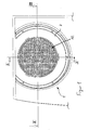
- a lamp 1 for motor vehicles essentially consists of a housing 2, a first light source device 3, one of the first light source device upstream second light source device 4, one of the first Light source device 3 associated reflector 5 and an opening of the reflector 5 covering lens 6.
- the lens 6 is a crystal clear cover 7 upstream, the opening of the housing 2 completely covers.
- the reflector 5 has a central opening in which a light source 8 first light source device 3 is arranged.
- the light source 8 can be used as Incandescent lamp or be designed as a gas discharge lamp.
- the second light source device 4 has a plurality of on a carrier element 9 uniformly distributed lighting elements 10.
- the Luminous elements 10 are designed as light-emitting diodes, which on a carrier plate or carrier plate trained carrier element 9 are held.
- the Carrier plate 9 is held on the housing 2 via axial feet (not shown).
- the carrier plate 9 is circular and rotationally symmetrical to the optical axis of the light source 8 of the first light source device 3 aligned.
- the lighting elements 10 are in passages 11 a multi-reflector part 12, which surrounds a plurality of one Miniature reflectors 13 assigned to the luminous element 10.
- the miniature reflectors 13 are hexagonal or trieder-shaped in cross section and form a homogeneous light distribution of the second light source device 4 in the direction of radiation.
- the lighting elements 10 can also be used as small incandescent lamps or be designed as neon lamps.
- a heat protection element is located between the light source 8 and the carrier plate 9 14 arranged, which covers the light source 8 cap-shaped. So that the LEDs 10 is protected from the heat generated by the light source 8 the heat protection element 14 from a heat absorbing or heat-dissipating material that is transparent to the light. In addition can the front surface should be painted for light and heat reflection.
- the multi-reflector part 12 is in one piece and opposite to the radiation direction extending holding arms 15 held on the housing 2 or the reflector 5.
- the lens 6 is complete colored yellow so that that emitted by the light source 8 and on the reflector 5 reflected white light after passing through the lens 6 as yellow Light is perceived.
- the first light source device 3 can therefore form a flashing light function that has a circular appearance. there are mainly outer portions of the lens 6 of the Light rays from the first light source device 3 are detected. About Translucent Light in the area of the second light source device 4 is permissible.
- a middle section of the lens 6 is perceived as a red color, since the main radiation power of the light emitting diodes 10 in a wavelength range lies, which corresponds to the color red of the light.
- the light of the red light emitting diodes 10 (LED) is through the miniature reflectors 13 in the direction of radiation converges so that a homogeneous light distribution is generated.
- the Passage of the light through the yellow colored lens 6 influences the Color impression is only insignificant, so that the second light source device 4 is suitable for the formation of brake light or tail light function.
- the lens 6 can also be of crystal-clear design, the first light source device 3 being used for Formation of a reversing light function is used.
- the first light source device 3 being used for Formation of a reversing light function is used.
- the crystal clear Lens 6 can be generated.
- the first light source device 3 can to form a brake light function and the second light source device 4 serve to form a flashing light function.
- the lens 6 can also have such a coloring, that the light emitted by the second light source device 4 is colored becomes.
- the outer first light source device 3 has a plurality of light emitting diodes, while the inner second light source device 4 as one or more light bulbs is trained.
- the miniature reflectors 13 can also be replaced by another optical collection system, for example, through a Fresnel optic.
- the multiple reflector part 112 through an additional lens with a plurality of Fresnel optics be provided.
- the heat protection element 14 can also be colored. With the first light source device 3 also a signal color such as red or yellow produce.
- the heat protection element 14 can act as a filter, that in combination generates the specified signal color with a colored lens.
- the filter can be colored green-yellow or turquoise and the Lens colored pink.
Landscapes
- Engineering & Computer Science (AREA)
- General Engineering & Computer Science (AREA)
- Mechanical Engineering (AREA)
- Physics & Mathematics (AREA)
- Microelectronics & Electronic Packaging (AREA)
- Optics & Photonics (AREA)
- Non-Portable Lighting Devices Or Systems Thereof (AREA)
Abstract
Description
- Figur 1
- eine Vorderansicht einer Leuchte,
- Figur 2
- einen Vertikalschnitt durch die Leuchte gemäß Linie II-II in Figur 1 und
- Figur 3
- einen Horizontalschnitt durch die Leuchte gemäß Linie III-III in Figur 1.
Claims (10)
- Leuchte für Fahrzeuge mit einer ersten Lichtquelleneinrichtung, einem der ersten Lichtquelleneinrichtung zugeordneten Reflektor und einer der ersten Lichtquelleneinrichtung vorgelagerten zweiten Lichtquelleneinrichtung, wobei die erste Lichtquelleneinrichtung und die zweite Lichtquelleneinrichtung durch eine gemeinsame Lichtscheibe abgedeckt sind, dadurch gekennzeichnet, dass die zweite Lichtquelleneinrichtung (4) eine Mehrzahl von eine zu der ersten Lichtquelleneinrichtung (3) unterschiedliche Farbgebung erzeugenden Leuchtelementen (10) aufweist, die auf einem gemeinsamen Trägerelement (9) angeordnet sind, und dass die Lichtscheibe (6) eine einzige vorgegebene Farbgebung aufweist.
- Leuchte nach Anspruch 1, dadurch gekennzeichnet, dass die Lichtscheibe eine solche Farbgebung aufweist, die ausschließlich die durch die erste Lichtquelleneinrichtung (3) oder durch die zweite Lichtquelleneinrichtung (4) emittierten Lichtstrahlen farblich prägt.
- Leuchte nach Anspruch 1 oder 2, dadurch gekennzeichnet, dass die Leuchtelemente (10) der zweiten Lichtquelleneinrichtung (4) auf dem Trägerelement (9) gleichmäßig angeordnet sind und dass den Leuchtelementen (10) jeweils ein Miniaturreflektor (13) zur Bildung einer Lichtverteilungsoptik zugeordnet sind.
- Leuchte nach einem der Ansprüche 1 bis 3, dadurch gekennzeichnet, dass die Miniaturreflektoren (13) im Querschnitt sechseckförmig oder triederförmig ausgebildet sind.
- Leuchte nach einem der Ansprüche 1 bis 4, dadurch gekennzeichnet, dass die Miniaturreflektoren (13) zu einem Vielreflektorenteil (12) mit Durchlässen (11) für die Leuchtelemente (10) zusammengefasst sind, wobei sich das Vielreflektorenteil (12) zwischen dem Trägerelement (9) und der Lichtscheibe (6) erstreckt.
- Leuchte nach einem der Ansprüche 1 bis 5, dadurch gekennzeichnet, dass zwischen der ersten Lichtquelleneinrichtung (3) und der zweiten Lichtquelleneinrichtung (4) ein Wärmeschutzelement (14) angeordnet ist.
- Leuchte nach einem der Ansprüche 1 bis 6, dadurch gekennzeichnet, dass die Leuchtelemente (10) der zweiten Lichtquelleneinrichtung (4) als Leuchtdioden ausgebildet sind.
- Leuchte nach einem der Ansprüche 1 bis 7, dadurch gekennzeichnet, dass die Leuchtdioden (10) ein Lichtbündel roter oder weißer Farbgebung emittieren und dass die Lichtscheibe (6) eine glasklare, gelbe oder rote Farbgebung aufweist.
- Leuchte nach einem der Ansprüche 1 bis 8, dadurch gekennzeichnet, dass der Lichtscheibe (6) eine glasklare Abdeckscheibe (7) vorgelagert ist.
- Leuchte nach einem der Ansprüche 1 bis 9, dadurch gekennzeichnet, dass die erste Lichtquelleneinrichtung (3) eine Glühlampe oder eine Gasentladungslampe aufweist.
Applications Claiming Priority (2)
| Application Number | Priority Date | Filing Date | Title |
|---|---|---|---|
| DE10060489 | 2000-12-06 | ||
| DE10060489A DE10060489A1 (de) | 2000-12-08 | 2000-12-08 | Leuchte für Fahrzeuge |
Publications (3)
| Publication Number | Publication Date |
|---|---|
| EP1213531A2 true EP1213531A2 (de) | 2002-06-12 |
| EP1213531A3 EP1213531A3 (de) | 2002-10-23 |
| EP1213531B1 EP1213531B1 (de) | 2011-05-18 |
Family
ID=7665916
Family Applications (1)
| Application Number | Title | Priority Date | Filing Date |
|---|---|---|---|
| EP01128678A Expired - Lifetime EP1213531B1 (de) | 2000-12-08 | 2001-12-01 | Leuchte für Fahrzeuge |
Country Status (2)
| Country | Link |
|---|---|
| EP (1) | EP1213531B1 (de) |
| DE (1) | DE10060489A1 (de) |
Cited By (6)
| Publication number | Priority date | Publication date | Assignee | Title |
|---|---|---|---|---|
| WO2004065172A1 (de) * | 2003-01-23 | 2004-08-05 | Bayerische Motoren Werke Aktiengesellschaft | Fahrzeugleuchte und verfahren zur anzeige unterschiedlicher signalbilder einer fahrzeugleuchte |
| WO2004106113A1 (de) * | 2003-05-28 | 2004-12-09 | Volkswagen Ag | Beleuchtungsvorrichtung für fahrzeuge mit einem leuchtdioden umfassenden leuchtmodul |
| EP1970250A1 (de) * | 2007-03-12 | 2008-09-17 | Odelo GmbH | Leuchte für Fahrzeuge, insbesondere für Kraftfahrzeuge |
| CN100519269C (zh) * | 2003-05-28 | 2009-07-29 | 大众汽车有限公司 | 带有包括发光二极管的照明模块的汽车照明装置 |
| FR2966558A1 (fr) * | 2010-10-21 | 2012-04-27 | Peugeot Citroen Automobiles Sa | Bloc optique de vehicule a fonction d'eclairage integrant une partie au moins d'une autre fonction d'eclairage dans une partie aval |
| FR2982551A1 (fr) * | 2011-11-10 | 2013-05-17 | Renault Sa | Projecteur pour vehicule automobile |
Families Citing this family (7)
| Publication number | Priority date | Publication date | Assignee | Title |
|---|---|---|---|---|
| DE20210225U1 (de) | 2002-06-27 | 2002-09-05 | Automotive Lighting Reutlingen | Leuchte für Fahrzeuge |
| DE20211647U1 (de) | 2002-07-23 | 2002-09-26 | Pintsch Bamag Antriebs- und Verkehrstechnik GmbH, 46537 Dinslaken | Signalleuchte und Leuchtenanordnung für Schienenfahrzeuge |
| DE10336974A1 (de) * | 2003-08-12 | 2005-03-10 | Hella Kgaa Hueck & Co | Signalleuchte für Fahrzeuge |
| DE10361488B4 (de) * | 2003-12-23 | 2012-05-31 | Volkswagen Ag | Fahrzeugleuchte |
| DE102006014226A1 (de) * | 2006-03-28 | 2007-10-04 | Volkswagen Ag | Beleuchtungseinheit für ein Fahrzeug mit zumindest zwei Lichtquellen |
| DE102016114242B4 (de) * | 2016-08-02 | 2020-10-08 | Frowein Ezh Gmbh | Abstrahleinheit für eine Operationsleuchte |
| FR3074563B1 (fr) * | 2017-12-05 | 2019-11-08 | Automotive Lighting Rear Lamps France | Dispositif de signalisation pour un vehicule automobile, comprenant un ou plusieurs ecrans lumineux eclaires de facon homogene |
Citations (2)
| Publication number | Priority date | Publication date | Assignee | Title |
|---|---|---|---|---|
| DE19514424A1 (de) | 1994-04-19 | 1995-11-30 | Koito Mfg Co Ltd | Zu zwei unterschiedlichen Lichtquellen kompatible Linse für eine Leuchte für ein Fahrzeug |
| DE19916845A1 (de) | 1999-04-14 | 2000-10-19 | Volkswagen Ag | Fahrzeugleuchte mit zwei Lichtquellen |
Family Cites Families (10)
| Publication number | Priority date | Publication date | Assignee | Title |
|---|---|---|---|---|
| DE2904267A1 (de) * | 1979-02-05 | 1980-08-14 | Westfaelische Metall Industrie | Farbiges licht abgebende signalleuchte fuer fahrzeuge |
| DE3315785A1 (de) * | 1983-04-30 | 1984-11-08 | Robert Bosch Gmbh, 7000 Stuttgart | Kraftfahrzeugleuchte |
| US4680678A (en) * | 1986-07-18 | 1987-07-14 | Stanley Electric Co., Ltd. | Lighting fixture for vehicle |
| JPH0745102A (ja) * | 1993-07-30 | 1995-02-14 | Stanley Electric Co Ltd | 車両用灯具 |
| FR2763385B1 (fr) * | 1997-05-15 | 1999-08-06 | Valeo Vision | Feu de signalisation pour vehicule automobile a synthese additive |
| DE19734748A1 (de) * | 1997-08-12 | 1999-02-18 | Reitter & Schefenacker Gmbh | Träger, vorzugsweise für Heckleuchten von Kraftfahrzeugen, sowie Verfahren zur Befestigung von elektronischen Bauteilen, vorzugsweise von LED's, an einem solchen Träger |
| DE19748522A1 (de) * | 1997-11-03 | 1999-05-12 | Siemens Ag | Verkehrstechnische Signalisierungseinrichtung mit aus Leuchtdioden zusammengesetzten Anzeigen |
| JP3173453B2 (ja) * | 1998-03-13 | 2001-06-04 | スタンレー電気株式会社 | 車両用信号灯具 |
| DE19921909A1 (de) * | 1998-07-17 | 2000-02-03 | Hella Kg Hueck & Co | Fahrzeugleuchte |
| FR2791121B1 (fr) * | 1999-03-19 | 2001-06-08 | Valeo Vision | Feu de signalisation multi-sources perfectionne pour vehicule automobile |
-
2000
- 2000-12-08 DE DE10060489A patent/DE10060489A1/de not_active Withdrawn
-
2001
- 2001-12-01 EP EP01128678A patent/EP1213531B1/de not_active Expired - Lifetime
Patent Citations (2)
| Publication number | Priority date | Publication date | Assignee | Title |
|---|---|---|---|---|
| DE19514424A1 (de) | 1994-04-19 | 1995-11-30 | Koito Mfg Co Ltd | Zu zwei unterschiedlichen Lichtquellen kompatible Linse für eine Leuchte für ein Fahrzeug |
| DE19916845A1 (de) | 1999-04-14 | 2000-10-19 | Volkswagen Ag | Fahrzeugleuchte mit zwei Lichtquellen |
Cited By (9)
| Publication number | Priority date | Publication date | Assignee | Title |
|---|---|---|---|---|
| WO2004065172A1 (de) * | 2003-01-23 | 2004-08-05 | Bayerische Motoren Werke Aktiengesellschaft | Fahrzeugleuchte und verfahren zur anzeige unterschiedlicher signalbilder einer fahrzeugleuchte |
| US7270455B2 (en) | 2003-01-23 | 2007-09-18 | Bayerische Motoren Werke Aktiengesellschaft | Vehicle light and method of indicating different signal patterns of a vehicle light |
| WO2004106113A1 (de) * | 2003-05-28 | 2004-12-09 | Volkswagen Ag | Beleuchtungsvorrichtung für fahrzeuge mit einem leuchtdioden umfassenden leuchtmodul |
| DE102004013082A1 (de) * | 2003-05-28 | 2005-01-05 | Volkswagen Ag | Beleuchtungsvorrichtung für Fahrzeuge mit einem Leuchtdioden umfassenden Leuchtmodul |
| CN100519269C (zh) * | 2003-05-28 | 2009-07-29 | 大众汽车有限公司 | 带有包括发光二极管的照明模块的汽车照明装置 |
| DE102004013082B4 (de) | 2003-05-28 | 2019-08-01 | Volkswagen Ag | Beleuchtungsvorrichtung für Fahrzeuge mit zwei Leuchtmodulen |
| EP1970250A1 (de) * | 2007-03-12 | 2008-09-17 | Odelo GmbH | Leuchte für Fahrzeuge, insbesondere für Kraftfahrzeuge |
| FR2966558A1 (fr) * | 2010-10-21 | 2012-04-27 | Peugeot Citroen Automobiles Sa | Bloc optique de vehicule a fonction d'eclairage integrant une partie au moins d'une autre fonction d'eclairage dans une partie aval |
| FR2982551A1 (fr) * | 2011-11-10 | 2013-05-17 | Renault Sa | Projecteur pour vehicule automobile |
Also Published As
| Publication number | Publication date |
|---|---|
| EP1213531B1 (de) | 2011-05-18 |
| DE10060489A1 (de) | 2002-06-13 |
| EP1213531A3 (de) | 2002-10-23 |
Similar Documents
| Publication | Publication Date | Title |
|---|---|---|
| EP0949450B1 (de) | Leuchte, insbesondere Heckleuchte, für Kraftfahrzeuge | |
| EP1213531B1 (de) | Leuchte für Fahrzeuge | |
| DE10207694A1 (de) | Lichteinheit für Fahrzeuge | |
| EP3196539A1 (de) | Leuchtvorrichtung mit mehreren halbleiterlichtquellen | |
| DE10249113A1 (de) | Leuchte, insbesondere Heckleuchte, für Fahrzeuge, vorzugsweise Kraftfahrzeuge | |
| WO2015193039A1 (de) | Signalgebung mittels halbleiter-lichtquellen | |
| DE19646042B4 (de) | Fahrzeug-Beleuchtungseinrichtung | |
| DE102004011600B4 (de) | Heckleuchte eines Fahrzeugs | |
| EP1431158B1 (de) | Signal- und Fahrlichtscheinwerfer für Schienenfahrzeuge | |
| DE102004024599A1 (de) | Reflektor für eine Beleuchtungseinrichtung | |
| DE1259747B (de) | Anordnung zum Verhindern von Phantomlicht in einer Signallichtanlage fuer Automobileod. dgl. | |
| DE102004013082B4 (de) | Beleuchtungsvorrichtung für Fahrzeuge mit zwei Leuchtmodulen | |
| DE102011104055A1 (de) | Leuchteinrichtung für ein Fahrzeug | |
| DE602004010962T2 (de) | Signalleuchte für Fahrzeuge | |
| DE19838224A1 (de) | Frontleuchtenanordnung für Kraftfahrzeuge | |
| DE102004020154B4 (de) | Leuchte für Fahrzeuge | |
| EP1544074B1 (de) | Signal- und Fahrlichtscheinwerfer für ein Schienenfahrzeug. | |
| DE10139812A1 (de) | Beleuchtungseinrichtung | |
| DE102015109816A1 (de) | Beleuchtungsvorrichtung für Fahrzeuge | |
| DE19838911B4 (de) | Beleuchtungseinrichtung eines Fahrzeugs | |
| DE10241023A1 (de) | Leuchte für Fahrzeuge, insbesondere Heckleuchte für Kraftfahrzeuge | |
| DE10036347A1 (de) | Leuchte für Fahrzeuge | |
| DE102004049318A1 (de) | Leuchteinheit für Fahrzeuge | |
| DE102005042611A1 (de) | Beleuchtungsvorrichtung für ein Fahrzeug mit zwei Gruppen von Lichtquellen für zumindest zwei Lichtfunktionen | |
| EP1524168B1 (de) | Signalleuchte für Schienenfahrzeuge |
Legal Events
| Date | Code | Title | Description |
|---|---|---|---|
| PUAI | Public reference made under article 153(3) epc to a published international application that has entered the european phase |
Free format text: ORIGINAL CODE: 0009012 |
|
| AK | Designated contracting states |
Kind code of ref document: A2 Designated state(s): AT BE CH CY DE DK ES FI FR GB GR IE IT LI LU MC NL PT SE TR |
|
| AX | Request for extension of the european patent |
Free format text: AL;LT;LV;MK;RO;SI |
|
| PUAL | Search report despatched |
Free format text: ORIGINAL CODE: 0009013 |
|
| AK | Designated contracting states |
Kind code of ref document: A3 Designated state(s): AT BE CH CY DE DK ES FI FR GB GR IE IT LI LU MC NL PT SE TR |
|
| AX | Request for extension of the european patent |
Free format text: AL;LT;LV;MK;RO;SI |
|
| 17P | Request for examination filed |
Effective date: 20030311 |
|
| AKX | Designation fees paid |
Designated state(s): DE FR GB IT |
|
| RBV | Designated contracting states (corrected) |
Designated state(s): DE ES FR GB IT |
|
| RAP1 | Party data changed (applicant data changed or rights of an application transferred) |
Owner name: HELLA KGAA HUECK & CO. |
|
| 17Q | First examination report despatched |
Effective date: 20080225 |
|
| GRAP | Despatch of communication of intention to grant a patent |
Free format text: ORIGINAL CODE: EPIDOSNIGR1 |
|
| RIC1 | Information provided on ipc code assigned before grant |
Ipc: F21S 8/10 20060101AFI20101230BHEP Ipc: B60Q 1/26 20060101ALI20101230BHEP |
|
| GRAS | Grant fee paid |
Free format text: ORIGINAL CODE: EPIDOSNIGR3 |
|
| GRAA | (expected) grant |
Free format text: ORIGINAL CODE: 0009210 |
|
| REG | Reference to a national code |
Ref country code: DE Ref legal event code: R081 Ref document number: 50115885 Country of ref document: DE Owner name: HELLA GMBH & CO. KGAA, DE Free format text: FORMER OWNER: HELLA KG HUECK & CO., 59557 LIPPSTADT, DE |
|
| AK | Designated contracting states |
Kind code of ref document: B1 Designated state(s): DE ES FR GB IT |
|
| REG | Reference to a national code |
Ref country code: GB Ref legal event code: FG4D Free format text: NOT ENGLISH |
|
| REG | Reference to a national code |
Ref country code: DE Ref legal event code: R096 Ref document number: 50115885 Country of ref document: DE Effective date: 20110630 |
|
| PG25 | Lapsed in a contracting state [announced via postgrant information from national office to epo] |
Ref country code: ES Free format text: LAPSE BECAUSE OF FAILURE TO SUBMIT A TRANSLATION OF THE DESCRIPTION OR TO PAY THE FEE WITHIN THE PRESCRIBED TIME-LIMIT Effective date: 20110829 |
|
| PLBE | No opposition filed within time limit |
Free format text: ORIGINAL CODE: 0009261 |
|
| STAA | Information on the status of an ep patent application or granted ep patent |
Free format text: STATUS: NO OPPOSITION FILED WITHIN TIME LIMIT |
|
| 26N | No opposition filed |
Effective date: 20120221 |
|
| PG25 | Lapsed in a contracting state [announced via postgrant information from national office to epo] |
Ref country code: IT Free format text: LAPSE BECAUSE OF FAILURE TO SUBMIT A TRANSLATION OF THE DESCRIPTION OR TO PAY THE FEE WITHIN THE PRESCRIBED TIME-LIMIT Effective date: 20110518 |
|
| REG | Reference to a national code |
Ref country code: DE Ref legal event code: R097 Ref document number: 50115885 Country of ref document: DE Effective date: 20120221 |
|
| PGFP | Annual fee paid to national office [announced via postgrant information from national office to epo] |
Ref country code: GB Payment date: 20121128 Year of fee payment: 12 |
|
| PGFP | Annual fee paid to national office [announced via postgrant information from national office to epo] |
Ref country code: FR Payment date: 20130107 Year of fee payment: 12 |
|
| GBPC | Gb: european patent ceased through non-payment of renewal fee |
Effective date: 20131201 |
|
| REG | Reference to a national code |
Ref country code: FR Ref legal event code: ST Effective date: 20140829 |
|
| PG25 | Lapsed in a contracting state [announced via postgrant information from national office to epo] |
Ref country code: GB Free format text: LAPSE BECAUSE OF NON-PAYMENT OF DUE FEES Effective date: 20131201 Ref country code: FR Free format text: LAPSE BECAUSE OF NON-PAYMENT OF DUE FEES Effective date: 20131231 |
|
| REG | Reference to a national code |
Ref country code: DE Ref legal event code: R084 Ref document number: 50115885 Country of ref document: DE |
|
| REG | Reference to a national code |
Ref country code: DE Ref legal event code: R079 Ref document number: 50115885 Country of ref document: DE Free format text: PREVIOUS MAIN CLASS: F21S0008100000 Ipc: F21S0043000000 |
|
| REG | Reference to a national code |
Ref country code: DE Ref legal event code: R082 Ref document number: 50115885 Country of ref document: DE Representative=s name: FIEDLER, OSTERMANN & SCHNEIDER - PATENTANWAELT, DE Ref country code: DE Ref legal event code: R082 Ref document number: 50115885 Country of ref document: DE Representative=s name: PATENTANWAELTE FIEDLER, OSTERMANN & SCHNEIDER, DE Ref country code: DE Ref legal event code: R081 Ref document number: 50115885 Country of ref document: DE Owner name: HELLA GMBH & CO. KGAA, DE Free format text: FORMER OWNER: HELLA KGAA HUECK & CO., 59557 LIPPSTADT, DE |
|
| PGFP | Annual fee paid to national office [announced via postgrant information from national office to epo] |
Ref country code: DE Payment date: 20201118 Year of fee payment: 20 |
|
| REG | Reference to a national code |
Ref country code: DE Ref legal event code: R071 Ref document number: 50115885 Country of ref document: DE |