EP1212552B1 - Carter unitaire pour un renvoi angulaire - Google Patents
Carter unitaire pour un renvoi angulaire Download PDFInfo
- Publication number
- EP1212552B1 EP1212552B1 EP00960621A EP00960621A EP1212552B1 EP 1212552 B1 EP1212552 B1 EP 1212552B1 EP 00960621 A EP00960621 A EP 00960621A EP 00960621 A EP00960621 A EP 00960621A EP 1212552 B1 EP1212552 B1 EP 1212552B1
- Authority
- EP
- European Patent Office
- Prior art keywords
- gearbox
- bevel gear
- output shaft
- casing
- gear
- Prior art date
- Legal status (The legal status is an assumption and is not a legal conclusion. Google has not performed a legal analysis and makes no representation as to the accuracy of the status listed.)
- Expired - Lifetime
Links
- 230000005540 biological transmission Effects 0.000 claims abstract description 94
- 230000008878 coupling Effects 0.000 claims description 15
- 238000010168 coupling process Methods 0.000 claims description 15
- 238000005859 coupling reaction Methods 0.000 claims description 15
- 238000013461 design Methods 0.000 claims description 15
- 239000000314 lubricant Substances 0.000 claims description 7
- 239000002826 coolant Substances 0.000 claims description 6
- 230000000295 complement effect Effects 0.000 claims description 4
- 238000003754 machining Methods 0.000 claims description 3
- 238000006243 chemical reaction Methods 0.000 description 4
- 238000009434 installation Methods 0.000 description 4
- 150000001875 compounds Chemical class 0.000 description 3
- 238000011161 development Methods 0.000 description 3
- 238000004519 manufacturing process Methods 0.000 description 3
- 230000009347 mechanical transmission Effects 0.000 description 3
- 238000013519 translation Methods 0.000 description 3
- 238000001816 cooling Methods 0.000 description 2
- 230000001419 dependent effect Effects 0.000 description 2
- 238000012549 training Methods 0.000 description 2
- 230000000712 assembly Effects 0.000 description 1
- 238000000429 assembly Methods 0.000 description 1
- 238000010276 construction Methods 0.000 description 1
- 238000006073 displacement reaction Methods 0.000 description 1
- 238000005553 drilling Methods 0.000 description 1
- 238000010348 incorporation Methods 0.000 description 1
- 230000010354 integration Effects 0.000 description 1
- 238000012423 maintenance Methods 0.000 description 1
- 238000003801 milling Methods 0.000 description 1
- 238000012986 modification Methods 0.000 description 1
- 230000004048 modification Effects 0.000 description 1
- 238000012545 processing Methods 0.000 description 1
Images


Classifications
-
- F—MECHANICAL ENGINEERING; LIGHTING; HEATING; WEAPONS; BLASTING
- F16—ENGINEERING ELEMENTS AND UNITS; GENERAL MEASURES FOR PRODUCING AND MAINTAINING EFFECTIVE FUNCTIONING OF MACHINES OR INSTALLATIONS; THERMAL INSULATION IN GENERAL
- F16H—GEARING
- F16H57/00—General details of gearing
- F16H57/02—Gearboxes; Mounting gearing therein
- F16H57/021—Shaft support structures, e.g. partition walls, bearing eyes, casing walls or covers with bearings
-
- F—MECHANICAL ENGINEERING; LIGHTING; HEATING; WEAPONS; BLASTING
- F16—ENGINEERING ELEMENTS AND UNITS; GENERAL MEASURES FOR PRODUCING AND MAINTAINING EFFECTIVE FUNCTIONING OF MACHINES OR INSTALLATIONS; THERMAL INSULATION IN GENERAL
- F16H—GEARING
- F16H1/00—Toothed gearings for conveying rotary motion
- F16H1/02—Toothed gearings for conveying rotary motion without gears having orbital motion
- F16H1/04—Toothed gearings for conveying rotary motion without gears having orbital motion involving only two intermeshing members
- F16H1/12—Toothed gearings for conveying rotary motion without gears having orbital motion involving only two intermeshing members with non-parallel axes
- F16H1/14—Toothed gearings for conveying rotary motion without gears having orbital motion involving only two intermeshing members with non-parallel axes comprising conical gears only
-
- F—MECHANICAL ENGINEERING; LIGHTING; HEATING; WEAPONS; BLASTING
- F16—ENGINEERING ELEMENTS AND UNITS; GENERAL MEASURES FOR PRODUCING AND MAINTAINING EFFECTIVE FUNCTIONING OF MACHINES OR INSTALLATIONS; THERMAL INSULATION IN GENERAL
- F16H—GEARING
- F16H57/00—General details of gearing
- F16H57/02—Gearboxes; Mounting gearing therein
- F16H57/033—Series gearboxes, e.g. gearboxes based on the same design being available in different sizes or gearboxes using a combination of several standardised units
-
- B—PERFORMING OPERATIONS; TRANSPORTING
- B60—VEHICLES IN GENERAL
- B60K—ARRANGEMENT OR MOUNTING OF PROPULSION UNITS OR OF TRANSMISSIONS IN VEHICLES; ARRANGEMENT OR MOUNTING OF PLURAL DIVERSE PRIME-MOVERS IN VEHICLES; AUXILIARY DRIVES FOR VEHICLES; INSTRUMENTATION OR DASHBOARDS FOR VEHICLES; ARRANGEMENTS IN CONNECTION WITH COOLING, AIR INTAKE, GAS EXHAUST OR FUEL SUPPLY OF PROPULSION UNITS IN VEHICLES
- B60K17/00—Arrangement or mounting of transmissions in vehicles
- B60K17/04—Arrangement or mounting of transmissions in vehicles characterised by arrangement, location or kind of gearing
- B60K17/16—Arrangement or mounting of transmissions in vehicles characterised by arrangement, location or kind of gearing of differential gearing
-
- B—PERFORMING OPERATIONS; TRANSPORTING
- B60—VEHICLES IN GENERAL
- B60K—ARRANGEMENT OR MOUNTING OF PROPULSION UNITS OR OF TRANSMISSIONS IN VEHICLES; ARRANGEMENT OR MOUNTING OF PLURAL DIVERSE PRIME-MOVERS IN VEHICLES; AUXILIARY DRIVES FOR VEHICLES; INSTRUMENTATION OR DASHBOARDS FOR VEHICLES; ARRANGEMENTS IN CONNECTION WITH COOLING, AIR INTAKE, GAS EXHAUST OR FUEL SUPPLY OF PROPULSION UNITS IN VEHICLES
- B60K17/00—Arrangement or mounting of transmissions in vehicles
- B60K17/22—Arrangement or mounting of transmissions in vehicles characterised by arrangement, location, or type of main drive shafting, e.g. cardan shaft
-
- B—PERFORMING OPERATIONS; TRANSPORTING
- B60—VEHICLES IN GENERAL
- B60Y—INDEXING SCHEME RELATING TO ASPECTS CROSS-CUTTING VEHICLE TECHNOLOGY
- B60Y2200/00—Type of vehicle
- B60Y2200/10—Road Vehicles
- B60Y2200/14—Trucks; Load vehicles, Busses
- B60Y2200/143—Busses
- B60Y2200/1432—Low floor busses
-
- Y—GENERAL TAGGING OF NEW TECHNOLOGICAL DEVELOPMENTS; GENERAL TAGGING OF CROSS-SECTIONAL TECHNOLOGIES SPANNING OVER SEVERAL SECTIONS OF THE IPC; TECHNICAL SUBJECTS COVERED BY FORMER USPC CROSS-REFERENCE ART COLLECTIONS [XRACs] AND DIGESTS
- Y10—TECHNICAL SUBJECTS COVERED BY FORMER USPC
- Y10T—TECHNICAL SUBJECTS COVERED BY FORMER US CLASSIFICATION
- Y10T74/00—Machine element or mechanism
- Y10T74/19—Gearing
- Y10T74/1956—Adjustable
- Y10T74/19585—Fixed axes
-
- Y—GENERAL TAGGING OF NEW TECHNOLOGICAL DEVELOPMENTS; GENERAL TAGGING OF CROSS-SECTIONAL TECHNOLOGIES SPANNING OVER SEVERAL SECTIONS OF THE IPC; TECHNICAL SUBJECTS COVERED BY FORMER USPC CROSS-REFERENCE ART COLLECTIONS [XRACs] AND DIGESTS
- Y10—TECHNICAL SUBJECTS COVERED BY FORMER USPC
- Y10T—TECHNICAL SUBJECTS COVERED BY FORMER US CLASSIFICATION
- Y10T74/00—Machine element or mechanism
- Y10T74/19—Gearing
- Y10T74/19642—Directly cooperating gears
- Y10T74/1966—Intersecting axes
- Y10T74/19665—Bevel gear type
-
- Y—GENERAL TAGGING OF NEW TECHNOLOGICAL DEVELOPMENTS; GENERAL TAGGING OF CROSS-SECTIONAL TECHNOLOGIES SPANNING OVER SEVERAL SECTIONS OF THE IPC; TECHNICAL SUBJECTS COVERED BY FORMER USPC CROSS-REFERENCE ART COLLECTIONS [XRACs] AND DIGESTS
- Y10—TECHNICAL SUBJECTS COVERED BY FORMER USPC
- Y10T—TECHNICAL SUBJECTS COVERED BY FORMER US CLASSIFICATION
- Y10T74/00—Machine element or mechanism
- Y10T74/21—Elements
- Y10T74/2186—Gear casings
Definitions
- the invention relates to a unit housing for an angular drive Gear unit, in detail with the features from the generic term of claim 1, further a housing for a transmission assembly and Transmission unit.
- Gear units are in a variety of different Executions known. These differ, for example, with regard to the type of speed / torque conversion implemented. This can for example purely mechanical or combined with others Conversion options are executed. Especially at Gear units with purely mechanical power transmission or combined mechanical and other power transmission is available increasingly the need for universality of the gear unit in Foreground. To implement an output at a certain angle become the transmission input shaft in such transmission assemblies Angular drives used, which combined with a basic gear unit become. These enable the realization of a certain angle between the transmission input shaft and the transmission output shaft. For different requirements, i.e.
- the invention is therefore based on the object a housing for a number of angle drives for the missions in Gear units with mechanical or combined power transmission continues to increase develop that overall gearbox assembly for different Output variants with a standardized housing with a minimal overall length the overall gear unit can be equipped. Furthermore, the Total gear unit from a gear unit by simple Modification can be developed for a wide variety of application requirements. In particular, is on the possibility of creating a unit housing for turn off the implementation of a wide variety of angular drives. The solution according to the invention should furthermore be characterized by a small distinguish constructive effort.
- a unit housing for a plurality of Angular drives comprising at least one bevel gear stage with a first Bevel gear and a second bevel gear, to realize different Angle between a transmission input shaft and a transmission output shaft, wherein the second bevel gear with the transmission output shaft at least is indirectly rotatably coupled, for a majority of the theoretically possible Angle drives with almost constant ratio i and constant Outside diameters of the individual bevel gears have identical outside dimensions on.
- the transmission output shaft and / or the second bevel gear are in the Unit housing assigned storage receiving devices. This are from the inner contour of the unit housing and / or replaceable, dimensioned to accommodate the bearings of the transmission output shaft Bearing support elements formed.
- Angular drives Most of the theoretically possible ones can be stored in the standard housing Angular drives is the intersection of the two limit positions Flank lines of the bevel gears can be written on.
- the limit positions preferably describe one Angular drive range between 90 and ⁇ 180 °
- the individual angular drives differ only in terms of angle described in the installed state between the Transmission input shaft and the transmission output shaft, which at the same time the angle between the lines of symmetry of the individual bevel gears and so that corresponds to the input and output of the angular drive.
- the solution according to the invention makes it possible with a single housing to enclose different angular drives; just the manufacturing, in particular the incorporation of the inner contour by milling, drilling or similar life the execution of the storage facility sets the Output angle fixed.
- the customer is therefore concerned with the dimensions of the Gear unit not dependent on different angular drives, but there is the possibility of a unit housing for one Gear unit from a basic gear unit with to offer a wide variety of angular drives.
- the creation of the inner contour for every theoretically possible angle between the transmission input shaft and the transmission output shaft can be by a appropriate machining of the inner wall of the housing.
- this has preferably two bearing support elements that the transmission output shaft are assigned to accommodate at least one bearing on each first bearing support element and a second bearing support element -.
- the Bearing support elements each form a running surface for the individual bearings.
- the first bearing support element serves to support the end area of the Transmission output shaft in the housing, while the second bearing support element the bearing of the transmission output shaft in the area of the exit from the Housing serves.
- bearing support elements forms at least one of the bearing support elements - first and / or second bearing support part of the outer wall of the housing, preferably both bearing support elements are part of the housing.
- the second bearing support element already shows Connections and / or bushings for equipment lines and / or Bushings for electrical lines, so that these for one certain angular drive independently of the rest of the housing are modifiable.
- Another standardization is the arrangement of a second Heat exchanger achieved on the second support element.
- the bearing support elements can be fastened to the inside wall of the housing different ways can be realized, for example by means of Fasteners.
- the bearing support elements preferably have uniform external dimensions, especially in the surface areas, which touch the inner wall of the housing, or with recesses or Interlock projections on the inner wall of the housing. This offers the advantage that the unit housing also without bearing support elements is designed uniformly for all theoretically possible angular drives, and only the actual support surfaces of the bearings on the bearing support elements must be trained differently.
- the housing for a gear unit comprising a Basic gear unit and a bevel gear with one of the Basic gearbox unit assigned basic gearbox is with one, assigned to the angular drive unit housing according to one of the Claims 1 to 9 equipped.
- the Angular drive comprises at least one bevel gear stage with a first bevel gear and a second bevel gear, the second bevel gear with the Transmission output shaft is at least indirectly rotatably coupled.
- the rotationally fixed coupling can be non-positive and / or positive.
- An embodiment is preferably used in which the mechanical Gear part comprises a planetary gear stage and the rotationally fixed coupling of the first bevel gear is realized with the ring gear as a gear element.
- the Coupling can also be achieved by force and / or positive locking and / or Cohesion.
- the first bevel gear and the gear element of the planetary gear stage is designed as an integral unit.
- the first bevel gear of the angular drive and a gear element of the basic gear unit forming the output of the basic gear unit are preferably connected to one another in a rotationally fixed manner and arranged spatially close to one another.
- the basic gear unit comprises at least one planetary gear set with at least one ring gear, a sun gear, planet gears and a web or a spur gear set
- the output of the basic gear unit is formed by an element of the planetary gear set or the spur gear set.
- the first bevel gear of the bevel gear stage can be coupled in a rotationally fixed manner to the ring gear of the planet gear stage.
- the individual elements of the bevel gear stage can be with straight teeth or Helical teeth are executed. Gears are preferred used, in which the individual gear element a constant Has tooth height. When training as helical gearing is preferred an involute toothing is used. The helical toothing enables a particularly quiet mode of operation.
- the solution according to the invention makes it possible to use only one Angular drive housing to cover all angles and output torques.
- Through the The diameter-dependent design makes the bevel gear very compact and short. Maintenance is very simple, as is the installation and removal of the Bearing and gear wheels.
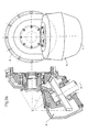
- the gear unit has a gear input shaft E and at least one gear output shaft A functioning as an output.
- Gearbox input shaft E and gearbox output shaft A are arranged such that their theoretical axes of rotation R E and R A run at an angle to one another.
- the transmission assembly 1 comprises at least one basic transmission assembly 25, which is arranged between the transmission input shaft E and the transmission output shaft A.
- the basic gear unit 25 comprises a mechanical gear part 2, and a bevel gear stage 3, which is designed as an angular drive 4 and is coupled to the transmission output shaft A.
- the gear unit 1 also has a gear housing 5, which is designed at least in two parts.
- this comprises at least one basic gear housing 6 and a unit housing 7, which at least partially encloses the angular drive 4 and can be connected to the gear housing 6.
- the unit housing 7 can also be made in several parts.
- the angular drive 4, which is formed by a bevel gear stage 3, has at least two intermeshing bevel gears - a first bevel gear 8 and a second bevel gear 9 -.
- the first bevel gear 8 is coaxial with the Gearbox input shaft E arranged.
- the second bevel gear 9, which with the Gearbox output shaft A is rotatably coupled, is in a certain Angle to the first bevel gear 8 arranged.
- the theoretical axes of rotation of the individual bevel gears or their axes of symmetry which correspond to the theoretical axes of rotation of the transmission input and transmission output shafts R E and R A , intersect at a point 10 which lies on the axis of symmetry of the gear unit 1. at this point the flank lines F also intersect with the toothing of the individual bevel gears when projected into a common plane E with the gear symmetry axis S G.
- the flank lines are designated here with F 81 , F 82 and F 91 , F 92 .
- the teeth of the individual bevel gears are preferably designed as straight teeth. However, designs with helical teeth or curved teeth, the flank lines of which are curved, are also conceivable.
- bevel gears with arcuate flank lines these can be designed as circular arcs, involutes or epicycloids.
- the bevel gears 8 and 9 are provided with a constant tooth height Z H8 and Z H9 .
- the following explanations relate to the straight toothing specifically described in FIG. 1. By analogy, these explanations can also be applied to other gears.
- angle drives 4 are provided, which are designed such that the individual flank lines with straight teeth or the flank lines projected into a plane with the transmission axis S G have different angles with the transmission axis S G can form.
- the gear housing 5 or the housing part 7 enclosing the angular drive is also designed.
- the second unit housing 7 is designed in such a standardized manner that it accommodates all theoretically possible or desired angular drives 4 is suitable, with the difference criterion being only the angle between the transmission input shaft E and the transmission output shaft A, while the transmission ratio and the outside diameter of the bevel gears are kept constant for the individual theoretically possible angles.
- the basic housing of the unit housing 7 is therefore designed for the two theoretical limit cases that the intersection 10 of the flank lines of the bevel gears 8 and 9 of the bevel gear stage 3 in the axial direction is closest to the gear housing 5 or to the unit housing 7 and furthest away.
- the first limit case can correspond, for example, to the situation of an angular drive 4 of 90 ° or even an angle greater than 90 °.
- a precise definition is not necessary, but should be within the theoretically possible framework, taking into account the constructive feasibility.
- an angular drive with an angle between the transmission input shaft E and the transmission output shaft A in the range from 90 ° to ⁇ 180 is preferred, the angle ⁇ 180 ° forming the second limit case.
- the outer contour for different angular drives 4 with essentially identical translation i and the same outer diameter d A of the individual bevel gears 8 and 9 remains constant, while adapting to different angular drives, in particular the arrangement of the bearings by designing or machining the inner contour of the Housing, in particular the unit housing 7, takes place.
- the inventive design of the unit housing for a majority of theoretically possible angular drives with almost constant translation i and constant outer diameter of the individual bevel gears 8 and 9 for includes different angular drives with identical external dimensions Bearing receptacles 20 that the transmission output shaft A and / or are assigned to the second bevel gear 9 in the unit housing 7.
- the bearing receiving devices 20 are of the inner contour 21 of the Unit housing and / or interchangeable, to accommodate the bearings dimensioned bearing support elements of the transmission output shaft. in the case illustrated according to the second alternative of Bearing support elements 22 and 30 associated with the transmission output shaft are. These serve to accommodate at least one bearing 31 and 32.
- the bearing support elements 22 and 30 each form a running surface 38 and 39 of the individual bearings 31 and 32.
- the first bearing support element 22 serves Bearing of the end area of the transmission output shaft A in the housing 7.
- Das second bearing support element 30 is used to support the transmission output shaft A. in the area of the exit from the housing 7.
- Both bearing support elements 22, 30- first and / or second bearing support element - form part of the Outer wall 40 of the housing 7.
- the support elements 22 and 30 are by means of Fastening elements 41 a, 41 b, 42a, 42b on the housing wall 43 are attachable.
- the close coupling of the first bevel gear 8 with the elements of mechanical transmission part 2 can be in different ways respectively.
- a connection was made chosen, which is characterized by a particularly compact design for the Characterized overall gear unit 1, since the first bevel gear 8 with a very large bevel gear diameter can be executed.
- the connection takes place here on a gear element of a planetary gear set 27 Basic gear unit 25, which simultaneously the output 15 for the Basic gear unit 25 and thus forms the input for the angle drive 4.
- the planetary gear set comprises a sun gear 12, a ring gear 26, Planet gears 13 and a bridge.
- the output 15 forming Gear element is formed by the ring gear 26 of the planetary gear set 27.
- the Coupling is carried out by realizing a non-rotatable connection Form and frictional connection.
- the non-rotatable connection is designated 33 here.
- the bevel gear 8 with a corresponding External teeth 28 executed with a complementary Internal teeth 29 on the ring gear 26 can be brought into engagement.
- the internal toothing 29 provided on the ring gear 26 in any case used.
- the ring gear is only in the axial direction Installation position in the gear unit 1 viewed extended, see above that in addition to the planet gears 34 of the planetary gear set 27 with the ring gear the outer toothing 28 of the bevel gear 8 meshes.
- the bevel gear 8 assigns this purpose in a second section 35, which is free of the Is bevel toothing, a correspondingly designed external toothing 28 on.
- the angular drive 4 is also assigned the housing part 7, which encloses the angular drive 4 and in the installed position in connection with the Basic housing 6 forms a structural unit.
- the angle drive 4 has corresponding Bearing arrangements 36 and an axis 37 for support, which is stationary in the housing part 7 is arranged on.
- the housing part 7 can be in one piece, however, it can also be made in several parts, as shown in FIG. 1.
- the Multi-part design is preferred to simplify assembly.
- the execution of the angle drive 4 as a modular unit offers the Advantage that this as a whole in a simple manner in the Total gear unit 1 can be integrated. This is done by Push one into the other and thus engage the external toothing 28 and the internal toothing 29 of the ring gear. Securing against displacement in the axial direction by connecting the first bevel gear 8 on Housing part 7 and the one for realizing the overall gear unit 1 required connection between the housing part 7 and the Basic transmission housing 6 of the basic transmission unit 25. Additional Securing elements are not required.
- FIG. 2 illustrates in a schematically simplified representation the mounting of the transmission output shaft A for two different angles between the transmission input shaft E and the transmission output shaft A.
- the variant designated I corresponds to an angle ⁇ 1 between the transmission input shaft E and the transmission output shaft A of 60 °
- that with II designated variant designates the bearing, which corresponds to an angle ⁇ 2 of 80 ° for an arrangement of the transmission output shaft A to the transmission input shaft E.
- the unit housing 7 also has a through opening 23, which enables the output of the transmission output shaft A.
- a through opening 23 Preferably is a constant theoretical opening area 23 for all unit housings 7 intended.
- the maximum size corresponds to that of Transmission output shaft A theoretically traversable angle range ⁇ .
- the unit housing 7 is non-positive and / or positive with the Gear housing 6 connectable.
- the coupling is preferably carried out via Screw and / or plug connections.
- To implement the connection required recesses and through openings on Basic gear housing 6 and on the unit housing 7 are preferably such executed that a rotatability in the circumferential direction of the transmission unit 1st considered is possible to thus different arrangements of the Bevel gear stage 3, in particular the second bevel gear 9 and thus the Angular drive 4 related to the installation position of the gear unit and thus to realize the gear housing 5 compared to the latter.
- Possible Positions are as an example in FIGS. 3a and 3b for a view A. shown in Fig. 1 or 2.
- the embodiment of the unit housing 7 described in FIGS. 1 and 2 also allows a different from the conventional type Removal of the second bevel gear 9. While conventional Designs the second bevel gear 9 in the direction of the axis of symmetry Transmission output shaft A was removed, exists with the Design of the unit housing 7 according to the invention the possibility of Unit housing 7 first to be detached from the remaining gear housing 5 and after Solution of the transmission output shaft A from the bevel gear G in lateral Direction out of the interior 11 formed by the unit housing 7 roll. This makes it possible to move the entire bevel gear stage 3 in the axial direction Direction to move further into the interior of the gear housing 5, since the Unit housing 7 no longer depends on the size of the area Through opening 23 of the transmission output shaft A to an opening which also allows the second bevel gear 9 in this direction expand.
- the design of the gear housing 5 according to Figures 1 to 3, in particular the unit housing 7, enables the creation of a Unit housing, by means of which various angular drives 4 are covered can be. Only the design or manufacturing and processing the inner contour in the area of the second bevel gear, which with the Gearbox output shaft A is coupled, defines the output angle.
- the so-called unit housing 7 can be the angular drive 4 in the axial direction towards conventional versions Gearbox input shaft are going crazy.
- the very short construction takes place over the level of the flange mounting of the entire angular drive.
- the preferred configuration described leads to a free design of the Output side, which is in a short and material-saving design results.
- the basic gear unit can be tested without angular drive 4.
- Gear unit 1 with unit housing designed according to the invention, comprising the basic gear housing 6 and the unit housing 7.
- unit housing is not to be understood as meaning that this one complete completion, but this can also with Openings are provided, which in turn have lid-shaped elements are lockable.
- Fig. 4.1 illustrates the use of the invention Gear unit 1 in a bus drive with transversely installed Drive machine 30 for driving an axis 31, which between the second and third door in a bus is provided for the bus drive.
- the Drive machine 30 is with the gear unit 1 for the purpose of Torque / speed conversion coupled, the output shaft 32 of the mechanical transmission part runs coaxially to the transmission input shaft E.
- the Axle drive takes place here via the angular drive 4.51 in the middle of the axis 31.
- the Angle drive 4.51 takes an angle of 60 or 65 °. This Execution is particularly suitable for right-hand traffic.
- FIG. 4.2 illustrates an embodiment corresponding to FIG. 4.1 in schematically simplified representation based on a view of a Bus drive.
- the drive machine 30 is installed transversely and the Axle drive is also in the middle.
- the execution differs compared to that described in Fig. 4.1 by changing the Direction of power flow between drive machine 30 and transmission unit 1. This version is particularly suitable for left-hand traffic.
- Figures 4.3 and 4.4 illustrate examples of use in so-called Low-floor bus drives, the arrangement of the drive machine 30 in turn transversely to the direction of travel and the drive of the portal axis 31 off-center, i.e. offset, via an angular drive 4.53 or 4.54.
- the 5.3 is for right-hand traffic and the execution in 5.4 suitable for left-hand traffic.
- the angular drive i.e. the angle between transmission input shaft E and transmission output shaft A is here 80 °.
- FIG. 5 illustrates a preferred further development of the Unit housing according to Figures 1 to 4.
- Heat exchanger 43 directly to the gear housing in the area of Gearbox output shaft A flanged.
- the conventional versions Oil hose lines used should be omitted, what by a appropriate training of the unit housing 7 with accordingly integrated cooling channels 44, preferably directly into the housing wall poured, is achieved.
Landscapes
- Engineering & Computer Science (AREA)
- General Engineering & Computer Science (AREA)
- Mechanical Engineering (AREA)
- Gear Transmission (AREA)
- General Details Of Gearings (AREA)
- Arrangement Or Mounting Of Propulsion Units For Vehicles (AREA)
- Arrangement Of Transmissions (AREA)
- Telephone Function (AREA)
- Vehicle Body Suspensions (AREA)
- Percussion Or Vibration Massage (AREA)
- Rear-View Mirror Devices That Are Mounted On The Exterior Of The Vehicle (AREA)
- Electrophonic Musical Instruments (AREA)
Claims (20)
- Carter unitaire (7) pour une pluralité de renvois angulaires (4), comprenant au moins un étage de roues coniques (3) avec une première roue conique (8) et une deuxième roue conique (9), destiné à réaliser différents angles entre un arbre d'entrée et un arbre de sortie d'une transmission (E, A), la deuxième roue conique (9) pouvant être couplée solidaire en rotation au moins indirectement avec l'arbre d'entrée (A) de la transmission;caractérisé par les particularités suivantes :1.1 le carter unitaire (7) est réalisé pour une pluralité des renvois angulaires (4) théoriquement possibles avec les particularités suivantes :avec des dimensions extérieures identiques ;démultiplication i quasiment constante etdiamètre extérieur des différentes roues coniques (8,9) quasiment identique1.2 des dispositifs de réception de logements de paliers sont associés à l'arbre de sortie (A) de la transmission et/ou à la deuxième roue conique (9);1.3 les dispositifs de réception de logements de paliers (20) sont formés par le contour intérieur (21) du carter unitaire (7) et/ou par des éléments porteurs de paliers (30, 22) échangeables, dimensionnés pour la réception de logements des paliers (31, 32) de l'arbre de sortie (A) de la transmission1.4 la pluralité des renvois angulaires (4) théoriquement possibles logeables dans le carter unitaire (7) peuvent être décrits par deux positions limites des points d'intersection des lignes de flanc (F81, F82, F91, F92) des roues coniques ;1.5. une première position limite pour le renvoi angulaire avec l'angle théoriquement le plus grand possible entre l'arbre d'entrée (E) et l'arbre de sortie (A) de la transmission est caractérisée par le point d'intersection le plus proche du carter (7) et une deuxième position limite pour le renvoi angulaire (4) avec l'angle théoriquement le plus petit possible entre l'arbre d'entrée (E) et l'arbre de sortie (A) de la transmission par le point d'intersection des lignes de flanc (F81, F82, F91, F92) le plus éloigné du carter.
- Carter unitaire (7) selon la revendication 1, caractérisé en ce que les positions limites décrivent un domaine de renvoi angulaire situé dans la plage de 90 à moins de 180°.
- Carter unitaire (7) selon l'une des revendications 1 ou 2, caractérisé en ce que le contour intérieur pour chaque angle théoriquement possible entre l'arbre d'entrée (E) et l'arbre de sortie (A) de la transmission peut être obtenu par un usinage approprié par enlèvement de copeaux de la paroi intérieure du carter.
- Carter unitaire (7) selon l'une des revendications 1 ou 2, caractérisé par les particularités suivantes :4.1 le dispositif de réception de paliers (20) de l'arbre de sortie (A) de la transmission présente deux éléments porteurs de paliers (30, 22) qui sont associés à l'arbre de sortie (A) de la transmission respectivement pour la réception d'au moins un palier (31, 32) - un premier élément porteur de palier (22) et un deuxième élément porteur de palier (30) - ;4.2 les éléments porteurs de paliers (22,30) forment respectivement une surface de roulement (38,39) des différents paliers (31, 32).
- Carter unitaire (7) selon la revendication 4, caractérisé par les particularités suivantes :5.1 un premier élément porteur de paliers (22) sert à loger dans le carter (7) la zone d'extrémité de l'arbre de sortie (A) de la transmission ;5.2 un deuxième élément porteur de paliers (30) sert à loger en dehors du carter (7) l'arbre de sortie (A) de la transmission, dans sa zone de sortie.
- Carter unitaire (7) selon l'une des revendications 4 ou 5, caractérisé en ce que, au moins un des éléments porteurs de paliers (22, 30) - le premier et/ou le deuxième élément porteur de paliers - forme une partie de la paroi extérieure (40) du carter (7) .
- Carter unitaire (7) selon l'une des revendications 5 ou 6, caractérisé en ce que le deuxième élément porteur de paliers (22,30) présente des espaces et/ou des passages pour des conduites de fluide de fonctionnement et/ou des passages pour des lignes électriques.
- Carter unitaire (7) selon l'une des revendications 5 à 7, caractérisé en ce qu'un échangeur de chaleur (43) est agencé sur le deuxième élément porteur (30).
- Carter unitaire (7) selon l'une des revendications 4 à 8, caractérisé en ce que les éléments porteurs (22, 30) peuvent être fixés à l'aide d'éléments de fixation (41, 42) à la paroi intérieure du carter.
- Carter (5) pour une unité de transmission (1), comportant une unité de transmission de départ (25) et un renvoi angulaire avec un carter de transmission de départ (6) affecté à l'unité de transmission de départ et avec un carter unitaire (7) affecté au renvoi angulaire selon l'une des revendications 1 à 9.
- Carter (5) selon la revendication 10, caractérisé par les particularités suivantes :11.1 dans le carter de transmission de départ (6) sont agencés une pluralité de canaux pour l'amenée de fluide de fonctionnement et/ou de lubrifiant et/ou d'agent réfrigérant ;11.2 à la pluralité de canaux pour l'amenée de fluide de fonctionnement et/ou- de lubrifiant et/ou d'agent réfrigérant sont affectés de manière correspondante des canaux de raccordement complémentaires dans le carter unitaire (7), lesquels forment lors de la réunion du carter de la transmission de départ (6) et du carter unitaire (7), des canaux qui s'étendent à travers l'unité de transmission (1) pour l'amenée de fluide de fonctionnement et/ou de lubrifiant et/ou d'agent réfrigérant.
- Unité de transmission (1)12.1 avec un arbre d'entrée (E) et un arbre de sortie (A) de transmission;12.2 comportant, agencés entre l'arbre d'entrée (E) et l'arbre de sortie (A) de la transmission, une transmission de départ (25) et un renvoi angulaire (4) qui est relié au moins indirectement solidaire en rotation avec l'organe de sortie de la transmission de départ (25) ;12.3 le renvoi angulaire comprend au moins un étage de roues coniques (3) avec une première roue conique (8) et une deuxième roue conique (9), la deuxième roue conique (9) pouvant être couplée solidaire en rotation au moins indirectement avec l'arbre de sortie (A) de la transmission;12.4 avec un carter (5) selon l'une des revendications 9 à 11.
- Unité de transmission (1) selon la revendication 12, caractérisée en ce que la première roue conique (8) du renvoi angulaire (14) et un élément de transmission formant l'organe de sortie de l'unité de transmission de départ (25) sont reliés ensemble au moins indirectement solidaires en rotation avec l'unité de transmission (25) et sont agencés spatialement à proximité l'un de l'autre.
- Unité de transmission (1) selon la revendication 13, caractérisée par les particularités suivantes :14.1 l'unité de transmission de départ (25) comprend au moins un jeu de roues planétaires (27) avec au moins une couronne de train planétaire (26), une roue solaire (12), des roues planétaires (13) et un porte-satellites (14) ou un jeu de pignons droits ;14.2 l'organe de sortie de l'unité de transmission de départ (25) est formé par un élément du jeu de roues planétaires (27) ou du jeu de pignons droits.
- Unité de transmission (1) selon la revendication 14, caractérisée en ce que la première roue conique (8) de l'étage de roues coniques (3) peut être couplée solidaire en rotation avec la couronne de train planétaire (26) de l'étage de roues planétaires (27).
- Unité de transmission (1) selon l'une des revendications 14 ou 15, caractérisée en ce que le couplage est réalisé par adhérence et/ou mécaniquement.
- Unité de transmission (1) selon la revendication 14 ou 15, caractérisée en ce que le couplage solidaire en rotation est réalisé par une structure intégrant la première roue conique (8) et l'arbre de sortie de la partie mécanique de la transmission ou la première roue conique (8) et l'élément de transmission de la partie mécanique de la transmission.
- Unité de transmission (1) selon l'une des revendications 12 à 17, caractérisée en ce que la denture des roues coniques (8,9) qui engrènent ensemble est conçue comme une denture droite.
- Unité de transmission (1) selon l'une des revendications 12 à 17, caractérisée en ce que la denture des roues coniques (8,9) de l'étage de roues coniques (3) qui engrènent ensemble est conçue comme un engrenage hélicoïdal.
- Unité de transmission (1) selon l'une des revendications 18 ou 19, caractérisée en ce que les roues coniques (8,9) de l'étage de roues coniques (3) présentent des éléments de denture ayant une hauteur de dents constante.
Applications Claiming Priority (3)
| Application Number | Priority Date | Filing Date | Title |
|---|---|---|---|
| DE29916006U DE29916006U1 (de) | 1999-09-14 | 1999-09-14 | Einheitsgehäuse für einen Winkeltrieb |
| DE29916006U | 1999-09-14 | ||
| PCT/EP2000/008755 WO2001020196A1 (fr) | 1999-09-14 | 2000-09-07 | Carter unitaire pour un renvoi angulaire |
Publications (2)
| Publication Number | Publication Date |
|---|---|
| EP1212552A1 EP1212552A1 (fr) | 2002-06-12 |
| EP1212552B1 true EP1212552B1 (fr) | 2003-06-04 |
Family
ID=8078785
Family Applications (1)
| Application Number | Title | Priority Date | Filing Date |
|---|---|---|---|
| EP00960621A Expired - Lifetime EP1212552B1 (fr) | 1999-09-14 | 2000-09-07 | Carter unitaire pour un renvoi angulaire |
Country Status (6)
| Country | Link |
|---|---|
| US (2) | US6810770B1 (fr) |
| EP (1) | EP1212552B1 (fr) |
| JP (1) | JP3782969B2 (fr) |
| AT (1) | ATE242443T1 (fr) |
| DE (5) | DE29916006U1 (fr) |
| WO (1) | WO2001020196A1 (fr) |
Families Citing this family (15)
| Publication number | Priority date | Publication date | Assignee | Title |
|---|---|---|---|---|
| DE10062039C2 (de) * | 2000-12-13 | 2003-08-21 | Sew Eurodrive Gmbh & Co | Baureihe von ein-oder mehrstufigen Getrieben |
| DE10314733A1 (de) * | 2003-03-31 | 2004-10-28 | Voith Turbo Gmbh & Co. Kg | Getriebe-Wärmetauscher-Einheit |
| DE10323114B4 (de) * | 2003-05-22 | 2007-03-01 | Dr.Ing.H.C. F. Porsche Ag | Lageraufnahme und Verfahren zum Herstellen einer Lageraufnahme |
| DE202004011547U1 (de) | 2004-07-23 | 2004-10-07 | As-Antriebstechnik Und Service Gmbh | Getriebe mit Adapterstopfen |
| DE102004038518A1 (de) * | 2004-08-07 | 2006-03-16 | Zf Friedrichshafen Ag | Antriebsanordnung für ein Kraftfahrzeug, insbesondere einen Niederflurbus |
| DE102007004964B4 (de) * | 2007-01-26 | 2012-05-16 | Sew-Eurodrive Gmbh & Co. Kg | Getriebe mit Schmierölpumpe und Getriebe-Baureihe |
| DE102007004965B4 (de) * | 2007-01-26 | 2012-05-16 | Sew-Eurodrive Gmbh & Co. Kg | Getriebe mit Ölkreislauf-Verrohrung und Getriebe-Baureihe |
| US9726149B2 (en) * | 2011-01-18 | 2017-08-08 | Hamilton Sundstrand Corporation | Spiral bevel gear set for ram air turbine |
| CN102242794A (zh) * | 2011-05-31 | 2011-11-16 | 国营红峰机械厂 | 一种斜交角谐波减速器 |
| RU2481509C1 (ru) * | 2011-10-27 | 2013-05-10 | Открытое акционерное общество "Авиадвигатель" | Устройство для сборки конической зубчатой передачи |
| CN105172587A (zh) * | 2015-09-24 | 2015-12-23 | 重庆大江工业有限责任公司 | 一种发动机后置的z型客车的后驱动桥 |
| US10807469B2 (en) * | 2018-08-30 | 2020-10-20 | Arboc Specialty Vehicles, Llc | Motor vehicle drive arrangement |
| CN110566632A (zh) * | 2019-08-05 | 2019-12-13 | 厦门丰泰国际新能源汽车有限公司 | 发动机、变速箱和角传动器的总成结构 |
| CN110792731A (zh) * | 2019-10-22 | 2020-02-14 | 北京动力机械研究所 | 一种用于长寿命小型涡扇发动机的中心传动结构 |
| CN114278719A (zh) * | 2021-11-19 | 2022-04-05 | 江苏摩多利传动机械制造有限公司 | 一种行星减速机直角结构 |
Family Cites Families (27)
| Publication number | Priority date | Publication date | Assignee | Title |
|---|---|---|---|---|
| DE837629C (de) * | 1950-07-25 | 1952-04-28 | Otto Kuehne | Getriebe mit veraenderlichem Winkel von Antriebs- und Abtriebswelle |
| DE902699C (de) * | 1951-11-29 | 1954-01-25 | Fritz Hinze | Kegelradgetriebe |
| US2910882A (en) * | 1957-11-04 | 1959-11-03 | Falk Corp | Housed selective-angle speed-reducer |
| DE1284804B (de) * | 1964-04-18 | 1968-12-05 | Wuelfel Eisenwerk | Zweiteiliges Getriebegehaeuse |
| US3350958A (en) | 1966-01-10 | 1967-11-07 | Ernest R Casale | V-drive transmission |
| FR2395855A1 (fr) | 1977-06-30 | 1979-01-26 | Pont A Mousson | Mecanisme de transmission pour vehicules automobiles, notamment pour vehicules automobiles de transport collectif |
| US4339965A (en) * | 1977-11-07 | 1982-07-20 | The J. B. Foote Foundry Co. | Transaxle with back-up flange |
| DE2829895C2 (de) * | 1978-07-07 | 1983-10-06 | Volkswagenwerk Ag, 3180 Wolfsburg | Winkelgetriebe für eine Fahrzeuglenkung |
| US4463823A (en) * | 1981-04-02 | 1984-08-07 | Honda Giken Kogyo Kabushiki Kaisha | Power transmission unit for a motorcycle |
| JPS5874952A (ja) * | 1981-10-29 | 1983-05-06 | Honda Motor Co Ltd | 変速機における最終駆動軸用軸受の支持及び封絨装置 |
| US4553624A (en) * | 1983-06-06 | 1985-11-19 | Kubota, Ltd. | Front-wheel driving apparatus |
| JPH0351540Y2 (fr) * | 1985-08-02 | 1991-11-06 | ||
| FR2610057A1 (fr) * | 1987-01-26 | 1988-07-29 | Boni Alfred | Organe de transmission de mouvement rotatif reglable, destine a relier deux arbres dans un angle quelconque compris entre 180 et 60 degres |
| GB2223068B (en) * | 1988-06-11 | 1992-03-04 | Gkn Axles | Axle drive unit |
| JPH0217244A (ja) | 1988-07-01 | 1990-01-22 | Koyo Seiko Co Ltd | 歯車装置 |
| JPH0351567A (ja) * | 1989-07-17 | 1991-03-05 | Tochigi Fuji Ind Co Ltd | 動力伝達装置 |
| JPH03117761A (ja) * | 1989-09-29 | 1991-05-20 | Suzuki Motor Corp | シャフトドライブ式自動二輪車の動力伝達装置 |
| DE9102998U1 (de) | 1991-03-13 | 1991-07-18 | ASUG Getriebewerk Gotha GmbH, O-5800 Gotha | Bewegungsmechanismus zur Übertragung von Drehbewegungen in beliebiger Richtung |
| JP3117761B2 (ja) | 1991-10-09 | 2000-12-18 | 三井化学株式会社 | ポリプロピレン樹脂組成物 |
| JP2716621B2 (ja) * | 1992-03-26 | 1998-02-18 | 石川島芝浦機械株式会社 | トラクターの前輪駆動装置 |
| US5363723A (en) * | 1993-02-23 | 1994-11-15 | Ryobi Outdoor Products, Inc. | Angle gear drive |
| DE4313322C2 (de) * | 1993-04-23 | 2001-08-02 | Porsche Ag | Differential für den Achsantrieb eines Kraftfahrzeuges |
| JPH09210144A (ja) | 1996-02-05 | 1997-08-12 | Mitsubishi Heavy Ind Ltd | 歯車伝動装置 |
| US5807200A (en) * | 1996-08-23 | 1998-09-15 | Hydro-Gear Limited Partnership | Transaxle drive differential assembly |
| DE19727153C2 (de) * | 1997-06-26 | 1999-05-20 | Voith Turbo Kg | Mehrganggetriebe, insbesondere Sechsgang-Getriebe |
| WO1999045295A1 (fr) * | 1998-03-06 | 1999-09-10 | Voith Turbo Gmbh & Co. Kg | Boite de vitesses compound hydrodynamique-mecanique a plusieurs vitesses |
| EP1212554B1 (fr) * | 1999-09-14 | 2003-07-02 | Voith Turbo GmbH & Co. KG | Boite de vitesses |
-
1999
- 1999-09-14 DE DE29916006U patent/DE29916006U1/de not_active Expired - Lifetime
-
2000
- 2000-08-02 DE DE10042472A patent/DE10042472B4/de not_active Expired - Fee Related
- 2000-08-29 DE DE10042475A patent/DE10042475A1/de not_active Ceased
- 2000-09-07 US US10/070,872 patent/US6810770B1/en not_active Expired - Fee Related
- 2000-09-07 JP JP2001523545A patent/JP3782969B2/ja not_active Expired - Fee Related
- 2000-09-07 WO PCT/EP2000/008755 patent/WO2001020196A1/fr not_active Ceased
- 2000-09-07 AT AT00960621T patent/ATE242443T1/de not_active IP Right Cessation
- 2000-09-07 DE DE50002473T patent/DE50002473D1/de not_active Expired - Lifetime
- 2000-09-07 DE DE50002756T patent/DE50002756D1/de not_active Expired - Lifetime
- 2000-09-07 EP EP00960621A patent/EP1212552B1/fr not_active Expired - Lifetime
-
2004
- 2004-09-10 US US10/938,188 patent/US7210375B2/en not_active Expired - Fee Related
Also Published As
| Publication number | Publication date |
|---|---|
| JP2003509641A (ja) | 2003-03-11 |
| JP3782969B2 (ja) | 2006-06-07 |
| EP1212552A1 (fr) | 2002-06-12 |
| US20050160875A1 (en) | 2005-07-28 |
| DE50002473D1 (de) | 2003-07-10 |
| ATE242443T1 (de) | 2003-06-15 |
| US6810770B1 (en) | 2004-11-02 |
| DE10042472B4 (de) | 2006-04-06 |
| WO2001020196A1 (fr) | 2001-03-22 |
| DE10042475A1 (de) | 2001-07-26 |
| US7210375B2 (en) | 2007-05-01 |
| DE10042472A1 (de) | 2001-11-29 |
| DE50002756D1 (de) | 2003-08-07 |
| DE29916006U1 (de) | 2001-02-15 |
Similar Documents
| Publication | Publication Date | Title |
|---|---|---|
| EP1212552B1 (fr) | Carter unitaire pour un renvoi angulaire | |
| EP1194306B1 (fr) | Entrainement de roues | |
| EP3707334A1 (fr) | Mécanisme de réglage pour des applications dans le domaine des véhicules à moteur | |
| DE102019125397B4 (de) | Getriebe sowie Kraftfahrzeug mit Getriebe | |
| WO2022156944A1 (fr) | Groupe motopropulseur pour un véhicule automobile | |
| DE102019209470B4 (de) | Parksperrenanordnung mit Parksperrenrad und Torsionsdämpfer | |
| DE102021206732A1 (de) | Antriebsanordnung für ein Fahrzeug | |
| EP1511952A1 (fr) | Entrainement standard, gamme de fabrication a flasque intermediaire | |
| DE102012213920A1 (de) | Getriebebaueinheit und Antriebseinheit mit einer Getriebebaueinheit | |
| EP2066919B1 (fr) | Démultiplicateur à phase multiple | |
| EP3907420A1 (fr) | Engrenage à enroulement planispiralé, ainsi que composants d'entraînement de portail et entraînement de portail doté d'un tel engrenage | |
| EP1212554B1 (fr) | Boite de vitesses | |
| EP1551661B1 (fr) | Ligne d'arbres, notamment arbre de transmission et entrainement a bogies homocinetique pour vehicules ferroviaires | |
| DD294763A5 (de) | Getriebe | |
| DE10212671B4 (de) | Kegelradausgleichsgetriebe | |
| EP4722078A1 (fr) | Dispositif de réglage pour un espace d'engrènement entre un engrenage à vis sans fin et une vis sans fin, et mécanisme de transmission de direction | |
| EP1831590B1 (fr) | Dispositif, notamment engrenage planetaire, comprenant un corps de base en anneau | |
| EP3625880B1 (fr) | Ensemble de transmission et de moteur | |
| EP0679495A1 (fr) | Transmission pour extrudeuse à deux vis | |
| EP4100666B1 (fr) | Ensemble mécanisme d'inversion | |
| DE102005039350A1 (de) | Schließzylinder | |
| DE102024105720A1 (de) | Aktor mit einem E-Motor und einem Linearantrieb | |
| DE102022002482A1 (de) | Elektrische Antriebseinrichtung für ein Kraftfahrzeug, insbesondere für einen Kraftwagen, sowie Kraftfahrzeug | |
| DE102023203968A1 (de) | Getriebe und Antriebsstrang für ein Kraftfahrzeug | |
| EP4506216A1 (fr) | Unité de palier et actionneur |
Legal Events
| Date | Code | Title | Description |
|---|---|---|---|
| PUAI | Public reference made under article 153(3) epc to a published international application that has entered the european phase |
Free format text: ORIGINAL CODE: 0009012 |
|
| 17P | Request for examination filed |
Effective date: 20020307 |
|
| AK | Designated contracting states |
Kind code of ref document: A1 Designated state(s): AT BE CH CY DE DK ES FI FR GB GR IE IT LI LU MC NL PT SE |
|
| GRAH | Despatch of communication of intention to grant a patent |
Free format text: ORIGINAL CODE: EPIDOS IGRA |
|
| GRAH | Despatch of communication of intention to grant a patent |
Free format text: ORIGINAL CODE: EPIDOS IGRA |
|
| GRAA | (expected) grant |
Free format text: ORIGINAL CODE: 0009210 |
|
| AK | Designated contracting states |
Designated state(s): AT BE CH CY DE DK ES FI FR GB GR IE IT LI LU MC NL PT SE |
|
| PG25 | Lapsed in a contracting state [announced via postgrant information from national office to epo] |
Ref country code: IE Free format text: LAPSE BECAUSE OF FAILURE TO SUBMIT A TRANSLATION OF THE DESCRIPTION OR TO PAY THE FEE WITHIN THE PRESCRIBED TIME-LIMIT Effective date: 20030604 Ref country code: FI Free format text: LAPSE BECAUSE OF FAILURE TO SUBMIT A TRANSLATION OF THE DESCRIPTION OR TO PAY THE FEE WITHIN THE PRESCRIBED TIME-LIMIT Effective date: 20030604 Ref country code: NL Free format text: LAPSE BECAUSE OF FAILURE TO SUBMIT A TRANSLATION OF THE DESCRIPTION OR TO PAY THE FEE WITHIN THE PRESCRIBED TIME-LIMIT Effective date: 20030604 |
|
| REG | Reference to a national code |
Ref country code: GB Ref legal event code: FG4D Free format text: NOT ENGLISH |
|
| REG | Reference to a national code |
Ref country code: CH Ref legal event code: EP |
|
| GBT | Gb: translation of ep patent filed (gb section 77(6)(a)/1977) | ||
| REG | Reference to a national code |
Ref country code: IE Ref legal event code: FG4D Free format text: GERMAN |
|
| REF | Corresponds to: |
Ref document number: 50002473 Country of ref document: DE Date of ref document: 20030710 Kind code of ref document: P |
|
| PG25 | Lapsed in a contracting state [announced via postgrant information from national office to epo] |
Ref country code: PT Free format text: LAPSE BECAUSE OF FAILURE TO SUBMIT A TRANSLATION OF THE DESCRIPTION OR TO PAY THE FEE WITHIN THE PRESCRIBED TIME-LIMIT Effective date: 20030904 Ref country code: GR Free format text: LAPSE BECAUSE OF FAILURE TO SUBMIT A TRANSLATION OF THE DESCRIPTION OR TO PAY THE FEE WITHIN THE PRESCRIBED TIME-LIMIT Effective date: 20030904 Ref country code: DK Free format text: LAPSE BECAUSE OF FAILURE TO SUBMIT A TRANSLATION OF THE DESCRIPTION OR TO PAY THE FEE WITHIN THE PRESCRIBED TIME-LIMIT Effective date: 20030904 |
|
| PG25 | Lapsed in a contracting state [announced via postgrant information from national office to epo] |
Ref country code: LU Free format text: LAPSE BECAUSE OF NON-PAYMENT OF DUE FEES Effective date: 20030907 Ref country code: CY Free format text: LAPSE BECAUSE OF FAILURE TO SUBMIT A TRANSLATION OF THE DESCRIPTION OR TO PAY THE FEE WITHIN THE PRESCRIBED TIME-LIMIT Effective date: 20030907 |
|
| PG25 | Lapsed in a contracting state [announced via postgrant information from national office to epo] |
Ref country code: ES Free format text: LAPSE BECAUSE OF FAILURE TO SUBMIT A TRANSLATION OF THE DESCRIPTION OR TO PAY THE FEE WITHIN THE PRESCRIBED TIME-LIMIT Effective date: 20030915 |
|
| REG | Reference to a national code |
Ref country code: SE Ref legal event code: TRGR |
|
| PG25 | Lapsed in a contracting state [announced via postgrant information from national office to epo] |
Ref country code: MC Free format text: LAPSE BECAUSE OF NON-PAYMENT OF DUE FEES Effective date: 20030930 |
|
| NLV1 | Nl: lapsed or annulled due to failure to fulfill the requirements of art. 29p and 29m of the patents act | ||
| ET | Fr: translation filed | ||
| REG | Reference to a national code |
Ref country code: IE Ref legal event code: FD4D |
|
| PLBE | No opposition filed within time limit |
Free format text: ORIGINAL CODE: 0009261 |
|
| STAA | Information on the status of an ep patent application or granted ep patent |
Free format text: STATUS: NO OPPOSITION FILED WITHIN TIME LIMIT |
|
| 26N | No opposition filed |
Effective date: 20040305 |
|
| PG25 | Lapsed in a contracting state [announced via postgrant information from national office to epo] |
Ref country code: LI Free format text: LAPSE BECAUSE OF NON-PAYMENT OF DUE FEES Effective date: 20040930 Ref country code: CH Free format text: LAPSE BECAUSE OF NON-PAYMENT OF DUE FEES Effective date: 20040930 |
|
| REG | Reference to a national code |
Ref country code: CH Ref legal event code: PL |
|
| PGFP | Annual fee paid to national office [announced via postgrant information from national office to epo] |
Ref country code: AT Payment date: 20080923 Year of fee payment: 9 Ref country code: IT Payment date: 20080924 Year of fee payment: 9 |
|
| PGFP | Annual fee paid to national office [announced via postgrant information from national office to epo] |
Ref country code: GB Payment date: 20080924 Year of fee payment: 9 |
|
| PGFP | Annual fee paid to national office [announced via postgrant information from national office to epo] |
Ref country code: BE Payment date: 20080929 Year of fee payment: 9 Ref country code: SE Payment date: 20080924 Year of fee payment: 9 |
|
| PGFP | Annual fee paid to national office [announced via postgrant information from national office to epo] |
Ref country code: FR Payment date: 20080922 Year of fee payment: 9 |
|
| BERE | Be: lapsed |
Owner name: *VOITH TURBO G.M.B.H. & CO. K.G. Effective date: 20090930 |
|
| EUG | Se: european patent has lapsed | ||
| GBPC | Gb: european patent ceased through non-payment of renewal fee |
Effective date: 20090907 |
|
| REG | Reference to a national code |
Ref country code: FR Ref legal event code: ST Effective date: 20100531 |
|
| PG25 | Lapsed in a contracting state [announced via postgrant information from national office to epo] |
Ref country code: AT Free format text: LAPSE BECAUSE OF NON-PAYMENT OF DUE FEES Effective date: 20090907 |
|
| PG25 | Lapsed in a contracting state [announced via postgrant information from national office to epo] |
Ref country code: FR Free format text: LAPSE BECAUSE OF NON-PAYMENT OF DUE FEES Effective date: 20090930 |
|
| PG25 | Lapsed in a contracting state [announced via postgrant information from national office to epo] |
Ref country code: BE Free format text: LAPSE BECAUSE OF NON-PAYMENT OF DUE FEES Effective date: 20090930 |
|
| PG25 | Lapsed in a contracting state [announced via postgrant information from national office to epo] |
Ref country code: GB Free format text: LAPSE BECAUSE OF NON-PAYMENT OF DUE FEES Effective date: 20090907 |
|
| PGFP | Annual fee paid to national office [announced via postgrant information from national office to epo] |
Ref country code: DE Payment date: 20101025 Year of fee payment: 11 |
|
| PG25 | Lapsed in a contracting state [announced via postgrant information from national office to epo] |
Ref country code: IT Free format text: LAPSE BECAUSE OF NON-PAYMENT OF DUE FEES Effective date: 20090907 |
|
| PG25 | Lapsed in a contracting state [announced via postgrant information from national office to epo] |
Ref country code: SE Free format text: LAPSE BECAUSE OF NON-PAYMENT OF DUE FEES Effective date: 20090908 |
|
| PG25 | Lapsed in a contracting state [announced via postgrant information from national office to epo] |
Ref country code: DE Free format text: LAPSE BECAUSE OF NON-PAYMENT OF DUE FEES Effective date: 20130403 |
|
| REG | Reference to a national code |
Ref country code: DE Ref legal event code: R119 Ref document number: 50002473 Country of ref document: DE Effective date: 20130403 |