EP1211778A2 - Magnet holder for starter motor - Google Patents
Magnet holder for starter motor Download PDFInfo
- Publication number
- EP1211778A2 EP1211778A2 EP01111458A EP01111458A EP1211778A2 EP 1211778 A2 EP1211778 A2 EP 1211778A2 EP 01111458 A EP01111458 A EP 01111458A EP 01111458 A EP01111458 A EP 01111458A EP 1211778 A2 EP1211778 A2 EP 1211778A2
- Authority
- EP
- European Patent Office
- Prior art keywords
- magnet
- shunt
- holder
- yoke housing
- starter motor
- Prior art date
- Legal status (The legal status is an assumption and is not a legal conclusion. Google has not performed a legal analysis and makes no representation as to the accuracy of the status listed.)
- Withdrawn
Links
Images

Classifications
-
- H—ELECTRICITY
- H02—GENERATION; CONVERSION OR DISTRIBUTION OF ELECTRIC POWER
- H02K—DYNAMO-ELECTRIC MACHINES
- H02K1/00—Details of the magnetic circuit
- H02K1/06—Details of the magnetic circuit characterised by the shape, form or construction
- H02K1/12—Stationary parts of the magnetic circuit
- H02K1/17—Stator cores with permanent magnets
Definitions
- the present invention relates to a magnet holder for a starter motor, and in particular to a magnet holder for a starter motor which is fixed together with a magnet without welding a shunt to a yoke housing.
- an armature and a field unit are installed in a yoke housing for driving an engine by rotating a pinion in a starter motor installed for an engine operation of a vehicle.
- the pinion is driven based on a magnetic operation of the same. Therefore, the pinion rotates a ring gear of the engine for thereby driving the engine.
- a magnet type starter motor is installed in a yoke housing in such a manner that a magnet surrounds an outer portion of the armature without installing a field coil in the yoke housing.
- the magnet is stably fixed in the yoke housing by a certain member.
- a shunt 3(or pole) is installed in an inner surface of the yoke housing 1 in the magnetic force direction of the magnet 2, and a holder A is installed between the pole 3 and the magnet 2.
- a pair of opposite engaging portions B are installed at both ends of the holder. In a state that the holder A is installed between the pole 3 and the magnet 2, the engaging portion B is bent in the circumferential direction for thereby fixing the magnet 2.
- the shunts 3 are installed in the inner surface of the yoke housing 1 at a certain interval.
- the shunts 3 are installed in the inner surface of the yoke housing 1 by a welding method. Since the welding method is used at an initial stage, the productivity is decreased, and the fabrication cost and quality are decreased.
- a magnet holder for a starter motor which includes one end rolled in an inner surface of a yoke housing and the other end inserted between a magnet and a shunt for thereby being fixed together with a magnet without welding a shunt to a yoke housing.
- a magnet holder for a starter motor which includes a bend formation portion disposed based on a rolled shape in an inner surface of a yoke housing by a certain width, and a holder member arranged in such a manner that the shunt and magnet are closely contacted at one side of the bend formation portion for supporting a plurality of the same at a certain interval and deployed in a circumferential direction for preventing the shunt and magnet from being moved in an axial direction of the yoke housing in a magnet fixing holder for a starter motor installed in an inner surface of a yoke housing and closely fixing a magnet to a shunt.
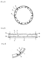
- Figure 4 is a plan view illustrating a magnet fixing holder for a starter motor according to the present invention
- Figure 5 is a detailed bottom view in the direction A of Figure 4
- Figure 6 is a side view in the direction B of Figure 5
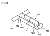
- Figure 7 is a partial perspective view for describing a magnet fixing holder for a starter motor according to the present invention.
- a magnet fixing holder for a starter motor installed in an inner surface of a yoke housing 1 and closely fixing a magnet 2 to a shunt 3
- a magnet fixing holder for a starter motor includes a bend formation portion 110 disposed based on a rolled shape in an inner surface of a yoke housing 1 by a certain width, and a holder member 120 arranged in such a manner that the shunt 3 and magnet 2 are closely contacted at one side of the bend formation portion 110 for supporting a plurality of the same at a certain interval and deployed in a circumferential direction for preventing the shunt 3 and magnet 2 from being moved in an axial direction of the yoke housing 1.
- the holder member 120 is extended from one side of the band formation member 110 and is formed in a reversed U shape.
- a support wall 121 is provided for supporting the side surfaces of the shunt 3 and the magnet 2.
- a deployment portion 122 is formed at both ends of the support wall 121 for limiting an axial direction movement of the shunt 3 and the magnet 2 by implementing an easily deployment in the circumferential direction.
- a cut portion 123 is formed at a lower portion of the deployment portion 122 formed at a free end of the holder member 120 for an easier deployment.
- a hole 124 is formed in a bottom surface of the holder portion 120 for fixing to the yoke housing 1 using a rivet.
- a bend formation portion 110 of the holder 100 is rolled in a circle shape and is received in an inner surface of the yoke housing 1, and the shunt 3 and magnet 2 are disposed between the holder member 120 and the support wall 121 of the holder member 120, and the deployment portion is deployed for thereby preventing an axial direction movement of the shunt 3 and the magnet 2.
- the construction of the yoke assembly formed of the yoke housing 1, the magnet 2, the shunt 3 and the holder 1090 is simplified for thereby decreasing a certain cost required for a welding operation, whereby it is possible to enhance the productivity and to decrease the fabrication cost.
- the fabrication process is simplified, and it is possible to fabricate a yoke assembly at a lower cost.
Landscapes
- Engineering & Computer Science (AREA)
- Power Engineering (AREA)
- Permanent Field Magnets Of Synchronous Machinery (AREA)
- Dc Machiner (AREA)
- Iron Core Of Rotating Electric Machines (AREA)
Abstract
Description
Claims (3)
- In a magnet fixing holder for a starter motor installed in an inner surface of a yoke housing and closely fixing a magnet to a shunt, a magnet fixing holder for a starter motor, comprising:a bend formation portion disposed based on a rolled shape in an inner surface of a yoke housing by a certain width; anda holder member arranged in such a manner that the shunt and magnet are closely contacted at one side of the bend formation portion for supporting a plurality of the same at a certain interval and deployed in a circumferential direction for preventing the shunt and magnet from being moved in an axial direction of the yoke housing.
- The holder of claim 1, wherein said holder member includes a support wall extended from one side of the bend formation portion for supporting the side surfaces of the shunt and magnet, and a deployment portion formed at both ends f the support wall for limiting an axial direction movement of the shunt and magnet for thereby implementing a deployment in an axial direction.
- The holder of claim 1, wherein a cut portion is formed at a lower portion of the deployment portion formed at a free end of the holder member for implementing an easier deployment.
Applications Claiming Priority (2)
| Application Number | Priority Date | Filing Date | Title |
|---|---|---|---|
| KR1020000071882A KR20020042118A (en) | 2000-11-30 | 2000-11-30 | A holder for magnet fixing of starter motor |
| KR2000071882 | 2000-11-30 |
Publications (2)
| Publication Number | Publication Date |
|---|---|
| EP1211778A2 true EP1211778A2 (en) | 2002-06-05 |
| EP1211778A3 EP1211778A3 (en) | 2004-01-21 |
Family
ID=19702426
Family Applications (1)
| Application Number | Title | Priority Date | Filing Date |
|---|---|---|---|
| EP01111458A Withdrawn EP1211778A3 (en) | 2000-11-30 | 2001-05-10 | Magnet holder for starter motor |
Country Status (4)
| Country | Link |
|---|---|
| US (1) | US20020063485A1 (en) |
| EP (1) | EP1211778A3 (en) |
| JP (1) | JP2002171703A (en) |
| KR (1) | KR20020042118A (en) |
Cited By (6)
| Publication number | Priority date | Publication date | Assignee | Title |
|---|---|---|---|---|
| WO2007051668A1 (en) * | 2005-11-07 | 2007-05-10 | Siemens Aktiengesellschaft | Electric motor with bent magnet elements fixed to the inner circumference of the motor housing |
| FR2904488A1 (en) * | 2006-07-31 | 2008-02-01 | Valeo Equip Electr Moteur | Electric motor for starting heat engine of e.g. motor vehicle, has magnet fixation part, whose length is lower than that of length of magnets, and provided with circular portion from which magnet fixation clip extends along axial direction |
| FR2910194A1 (en) * | 2006-12-15 | 2008-06-20 | Valeo Equip Electr Moteur | Six pole type electrical rotating machine i.e. direct drive starter, for motor vehicle, has stator including permanent magnets and support integrated to magnets, where number of magnets is greater than number of poles of machine |
| WO2008074954A1 (en) * | 2006-12-15 | 2008-06-26 | Valeo Equipements Electriques Moteur | Rotating electric machine, in particular for the starter of an automotive vehicle |
| FR2920259A1 (en) * | 2007-08-22 | 2009-02-27 | Valeo Equip Electr Moteur | ROTATING ELECTRIC MACHINE, ESPECIALLY FOR A MOTOR STARTER |
| EP2063514A1 (en) | 2007-11-26 | 2009-05-27 | Valeo Equipements Electriques Moteur | Stator for a rotating electric machine, in particular a starter |
Families Citing this family (28)
| Publication number | Priority date | Publication date | Assignee | Title |
|---|---|---|---|---|
| ITBZ20010043A1 (en) | 2001-09-13 | 2003-03-13 | High Technology Invest Bv | ELECTRIC GENERATOR OPERATED BY WIND ENERGY. |
| FR2856531B1 (en) * | 2003-05-30 | 2014-06-06 | Valeo Equip Electr Moteur | DEVICE FOR FIXING PERMANENT MAGNETS WITHIN A CYLINDER HEAD OF AN ELECTRIC MOTOR INDUCER |
| KR100525716B1 (en) * | 2003-05-30 | 2005-11-04 | 발레오전장시스템스코리아 주식회사 | Magnet holder of motor |
| DK1934474T3 (en) | 2005-09-21 | 2010-06-21 | Wilic S A R L | Bearing gasket assembly with maze gasket and screw gasket combination |
| ITBZ20050063A1 (en) | 2005-11-29 | 2007-05-30 | High Technology Invest Bv | LAMIERINI PACKAGE FOR GENERATORS AND ELECTRIC MOTORS AND PROCEDURE FOR ITS IMPLEMENTATION |
| ITBZ20050062A1 (en) | 2005-11-29 | 2007-05-30 | High Technology Invest Bv | PERMANENT MAGNET ROTOR FOR GENERATORS AND ELECTRIC MOTORS |
| JP5076521B2 (en) * | 2007-01-31 | 2012-11-21 | 株式会社デンソー | Starter motor |
| ITMI20081122A1 (en) | 2008-06-19 | 2009-12-20 | Rolic Invest Sarl | WIND GENERATOR PROVIDED WITH A COOLING SYSTEM |
| IT1390758B1 (en) | 2008-07-23 | 2011-09-23 | Rolic Invest Sarl | WIND GENERATOR |
| JP5146184B2 (en) * | 2008-08-01 | 2013-02-20 | 株式会社デンソー | Method for manufacturing magnet field motor |
| IT1391939B1 (en) | 2008-11-12 | 2012-02-02 | Rolic Invest Sarl | WIND GENERATOR |
| IT1391770B1 (en) | 2008-11-13 | 2012-01-27 | Rolic Invest Sarl | WIND GENERATOR FOR THE GENERATION OF ELECTRICITY |
| IT1392804B1 (en) | 2009-01-30 | 2012-03-23 | Rolic Invest Sarl | PACKAGING AND PACKAGING METHOD FOR POLE OF WIND GENERATORS |
| IT1393937B1 (en) | 2009-04-09 | 2012-05-17 | Rolic Invest Sarl | WIND TURBINE |
| IT1393707B1 (en) | 2009-04-29 | 2012-05-08 | Rolic Invest Sarl | WIND POWER PLANT FOR THE GENERATION OF ELECTRICITY |
| IT1394723B1 (en) | 2009-06-10 | 2012-07-13 | Rolic Invest Sarl | WIND POWER PLANT FOR THE GENERATION OF ELECTRICITY AND ITS CONTROL METHOD |
| IT1395148B1 (en) | 2009-08-07 | 2012-09-05 | Rolic Invest Sarl | METHOD AND APPARATUS FOR ACTIVATION OF AN ELECTRIC MACHINE AND ELECTRIC MACHINE |
| IT1397081B1 (en) | 2009-11-23 | 2012-12-28 | Rolic Invest Sarl | WIND POWER PLANT FOR THE GENERATION OF ELECTRICITY |
| IT1398060B1 (en) | 2010-02-04 | 2013-02-07 | Wilic Sarl | PLANT AND METHOD OF COOLING OF AN ELECTRIC GENERATOR OF AN AIR SPREADER, AND AIRCONDITIONER INCLUDING SUCH A COOLING PLANT |
| IT1399201B1 (en) | 2010-03-30 | 2013-04-11 | Wilic Sarl | AEROGENERATOR AND METHOD OF REMOVING A BEARING FROM A AIRCONDITIONER |
| IT1399511B1 (en) | 2010-04-22 | 2013-04-19 | Wilic Sarl | ELECTRIC GENERATOR FOR A VENTILATOR AND AEROGENER EQUIPPED WITH THIS ELECTRIC GENERATOR |
| JP5353921B2 (en) * | 2011-02-09 | 2013-11-27 | 株式会社デンソー | TIG welding method and apparatus |
| ITMI20110378A1 (en) | 2011-03-10 | 2012-09-11 | Wilic Sarl | ROTARY ELECTRIC MACHINE FOR AEROGENERATOR |
| ITMI20110377A1 (en) | 2011-03-10 | 2012-09-11 | Wilic Sarl | ROTARY ELECTRIC MACHINE FOR AEROGENERATOR |
| ITMI20110375A1 (en) | 2011-03-10 | 2012-09-11 | Wilic Sarl | WIND TURBINE |
| KR101997364B1 (en) * | 2017-12-11 | 2019-07-05 | 삼진정밀(주) | Stator parts assembling apparatus for start motor |
| US11264850B2 (en) * | 2019-09-05 | 2022-03-01 | Nidec Motor Corporation | Laminated rotor having deflecting magnet retaining prongs and support posts for the prongs |
| US11646616B2 (en) | 2020-02-04 | 2023-05-09 | Nidec Motor Corporation | Laminated spoked rotor with mechanical magnet retention |
Family Cites Families (7)
| Publication number | Priority date | Publication date | Assignee | Title |
|---|---|---|---|---|
| US2971107A (en) * | 1959-04-09 | 1961-02-07 | Gen Ind Co | Electric motors |
| JPS6079231U (en) * | 1983-11-05 | 1985-06-01 | 三菱電機株式会社 | Stator for magnetic rotating electric machines |
| CA1247686A (en) * | 1984-03-07 | 1988-12-28 | Nobuhiko Ogasawara | Magneto d.c. motor having elastic magnet mounting retainers |
| JPH03273840A (en) * | 1990-03-23 | 1991-12-05 | Hitachi Ltd | Fixing method for magnetic pole of permanent-magnet type electric rotary machine |
| JPH09168245A (en) * | 1995-12-15 | 1997-06-24 | Hitachi Ltd | Magnet type DC machine stator |
| FR2743209B1 (en) * | 1995-12-27 | 1998-03-27 | Valeo Systemes Dessuyage | PERMANENT MAGNET MOTOR WITH LOCKING STAPLES |
| JP3417332B2 (en) * | 1999-03-12 | 2003-06-16 | 株式会社デンソー | DC motor |
-
2000
- 2000-11-30 KR KR1020000071882A patent/KR20020042118A/en not_active Ceased
-
2001
- 2001-05-10 EP EP01111458A patent/EP1211778A3/en not_active Withdrawn
- 2001-05-18 US US09/861,134 patent/US20020063485A1/en not_active Abandoned
- 2001-06-14 JP JP2001179600A patent/JP2002171703A/en active Pending
Cited By (7)
| Publication number | Priority date | Publication date | Assignee | Title |
|---|---|---|---|---|
| WO2007051668A1 (en) * | 2005-11-07 | 2007-05-10 | Siemens Aktiengesellschaft | Electric motor with bent magnet elements fixed to the inner circumference of the motor housing |
| FR2904488A1 (en) * | 2006-07-31 | 2008-02-01 | Valeo Equip Electr Moteur | Electric motor for starting heat engine of e.g. motor vehicle, has magnet fixation part, whose length is lower than that of length of magnets, and provided with circular portion from which magnet fixation clip extends along axial direction |
| FR2910194A1 (en) * | 2006-12-15 | 2008-06-20 | Valeo Equip Electr Moteur | Six pole type electrical rotating machine i.e. direct drive starter, for motor vehicle, has stator including permanent magnets and support integrated to magnets, where number of magnets is greater than number of poles of machine |
| WO2008074954A1 (en) * | 2006-12-15 | 2008-06-26 | Valeo Equipements Electriques Moteur | Rotating electric machine, in particular for the starter of an automotive vehicle |
| US9130418B2 (en) | 2006-12-15 | 2015-09-08 | Valeo Equipements Electriques Moteur | Direct current rotating electric machine with stator having magnetised structure |
| FR2920259A1 (en) * | 2007-08-22 | 2009-02-27 | Valeo Equip Electr Moteur | ROTATING ELECTRIC MACHINE, ESPECIALLY FOR A MOTOR STARTER |
| EP2063514A1 (en) | 2007-11-26 | 2009-05-27 | Valeo Equipements Electriques Moteur | Stator for a rotating electric machine, in particular a starter |
Also Published As
| Publication number | Publication date |
|---|---|
| JP2002171703A (en) | 2002-06-14 |
| KR20020042118A (en) | 2002-06-05 |
| US20020063485A1 (en) | 2002-05-30 |
| EP1211778A3 (en) | 2004-01-21 |
Similar Documents
| Publication | Publication Date | Title |
|---|---|---|
| US20020063485A1 (en) | Magnet holder for starter motor | |
| JP6172065B2 (en) | Electromagnetic relay | |
| EP2037557B1 (en) | Axial gap-type electric motor | |
| EP0013175A2 (en) | Electromagnetic clutch | |
| US20100026125A1 (en) | Magneto field type motor and a method of manufacturing it | |
| US20050082138A1 (en) | Direct method of terminating the ground coil terminal to coil housing | |
| US6664684B1 (en) | Electric motor | |
| JP2007500497A (en) | Device for fixing a permanent magnet inside a cylindrical casing as a field coil of an electric motor | |
| US20050115339A1 (en) | Starter | |
| JP4069693B2 (en) | Method for manufacturing motor stator case | |
| JP3953923B2 (en) | Electric motor and method for manufacturing electric motor | |
| US6731037B1 (en) | Housing assembly structure of starter motor for vehicle | |
| JPH07118873B2 (en) | Magnet generator rotor | |
| JP3003748B2 (en) | Method for manufacturing rotor of magnet generator | |
| KR101904644B1 (en) | Brush holder assembly of startmotor for vehicle | |
| JP4252047B2 (en) | Motor device and manufacturing method thereof | |
| JP5496558B2 (en) | Commutator and manufacturing method thereof | |
| JP2021166469A (en) | Stator and manufacturing method thereof | |
| EP1891349B1 (en) | Pulley assembly for an electromagnetic power transmitting assembly | |
| JP2007082368A (en) | Miniature motor of open-sided bearing constitution | |
| KR100332696B1 (en) | Capstan motor and its bearing housing | |
| JPH0613600Y2 (en) | Structure of small electric motor | |
| JP2013093935A (en) | Case for rotary electric machine and rotary electric machine | |
| JPH0960661A (en) | Bearing support structure | |
| KR100328772B1 (en) | Center bracket structure of start motor |
Legal Events
| Date | Code | Title | Description |
|---|---|---|---|
| PUAI | Public reference made under article 153(3) epc to a published international application that has entered the european phase |
Free format text: ORIGINAL CODE: 0009012 |
|
| AK | Designated contracting states |
Kind code of ref document: A2 Designated state(s): AT BE CH CY DE DK ES FI FR GB GR IE IT LI LU MC NL PT SE TR |
|
| AX | Request for extension of the european patent |
Free format text: AL;LT;LV;MK;RO;SI |
|
| PUAL | Search report despatched |
Free format text: ORIGINAL CODE: 0009013 |
|
| AK | Designated contracting states |
Kind code of ref document: A3 Designated state(s): AT BE CH CY DE DK ES FI FR GB GR IE IT LI LU MC NL PT SE TR |
|
| AX | Request for extension of the european patent |
Extension state: AL LT LV MK RO SI |
|
| 17P | Request for examination filed |
Effective date: 20040303 |
|
| AKX | Designation fees paid |
Designated state(s): DE FR GB IT |
|
| 17Q | First examination report despatched |
Effective date: 20100303 |
|
| STAA | Information on the status of an ep patent application or granted ep patent |
Free format text: STATUS: THE APPLICATION IS DEEMED TO BE WITHDRAWN |
|
| 18D | Application deemed to be withdrawn |
Effective date: 20100914 |