EP1211502A2 - Selbstkalibrierender Isotopengas-Analysator - Google Patents
Selbstkalibrierender Isotopengas-Analysator Download PDFInfo
- Publication number
- EP1211502A2 EP1211502A2 EP02004740A EP02004740A EP1211502A2 EP 1211502 A2 EP1211502 A2 EP 1211502A2 EP 02004740 A EP02004740 A EP 02004740A EP 02004740 A EP02004740 A EP 02004740A EP 1211502 A2 EP1211502 A2 EP 1211502A2
- Authority
- EP
- European Patent Office
- Prior art keywords
- isotopic
- gas
- sample
- gas analyzer
- breath
- Prior art date
- Legal status (The legal status is an assumption and is not a legal conclusion. Google has not performed a legal analysis and makes no representation as to the accuracy of the status listed.)
- Withdrawn
Links
- 230000000155 isotopic effect Effects 0.000 title claims abstract description 204
- 238000000034 method Methods 0.000 claims abstract description 57
- 238000005259 measurement Methods 0.000 claims description 110
- 239000007789 gas Substances 0.000 description 469
- 239000000523 sample Substances 0.000 description 226
- 238000010521 absorption reaction Methods 0.000 description 105
- 229910002092 carbon dioxide Inorganic materials 0.000 description 78
- CURLTUGMZLYLDI-UHFFFAOYSA-N Carbon dioxide Chemical compound O=C=O CURLTUGMZLYLDI-UHFFFAOYSA-N 0.000 description 57
- 230000003287 optical effect Effects 0.000 description 46
- 230000035945 sensitivity Effects 0.000 description 32
- 238000004458 analytical method Methods 0.000 description 30
- 238000001745 non-dispersive infrared spectroscopy Methods 0.000 description 29
- 238000001514 detection method Methods 0.000 description 25
- 230000005855 radiation Effects 0.000 description 25
- 238000005070 sampling Methods 0.000 description 25
- 230000003595 spectral effect Effects 0.000 description 25
- 238000012360 testing method Methods 0.000 description 23
- 238000012937 correction Methods 0.000 description 20
- 230000007613 environmental effect Effects 0.000 description 20
- 230000036961 partial effect Effects 0.000 description 20
- 230000000694 effects Effects 0.000 description 17
- 230000006870 function Effects 0.000 description 17
- 230000005540 biological transmission Effects 0.000 description 16
- 230000008859 change Effects 0.000 description 14
- 230000005284 excitation Effects 0.000 description 13
- 238000001228 spectrum Methods 0.000 description 12
- 230000008569 process Effects 0.000 description 10
- 230000008901 benefit Effects 0.000 description 9
- 239000001569 carbon dioxide Substances 0.000 description 9
- 239000000203 mixture Substances 0.000 description 9
- 230000001360 synchronised effect Effects 0.000 description 9
- 238000009825 accumulation Methods 0.000 description 8
- 239000000835 fiber Substances 0.000 description 7
- 238000012935 Averaging Methods 0.000 description 6
- 238000013461 design Methods 0.000 description 6
- 238000010790 dilution Methods 0.000 description 6
- 239000012895 dilution Substances 0.000 description 6
- 238000012544 monitoring process Methods 0.000 description 6
- 238000005086 pumping Methods 0.000 description 6
- 238000010276 construction Methods 0.000 description 5
- 230000001419 dependent effect Effects 0.000 description 5
- 239000004973 liquid crystal related substance Substances 0.000 description 5
- 239000012528 membrane Substances 0.000 description 5
- 238000012545 processing Methods 0.000 description 5
- 230000002829 reductive effect Effects 0.000 description 4
- 238000000862 absorption spectrum Methods 0.000 description 3
- 229910052782 aluminium Inorganic materials 0.000 description 3
- XAGFODPZIPBFFR-UHFFFAOYSA-N aluminium Chemical compound [Al] XAGFODPZIPBFFR-UHFFFAOYSA-N 0.000 description 3
- 230000008033 biological extinction Effects 0.000 description 3
- 238000009530 blood pressure measurement Methods 0.000 description 3
- 238000004364 calculation method Methods 0.000 description 3
- 230000003750 conditioning effect Effects 0.000 description 3
- 239000000470 constituent Substances 0.000 description 3
- 239000012470 diluted sample Substances 0.000 description 3
- 230000003204 osmotic effect Effects 0.000 description 3
- 230000029058 respiratory gaseous exchange Effects 0.000 description 3
- 230000004044 response Effects 0.000 description 3
- 229910001220 stainless steel Inorganic materials 0.000 description 3
- 239000010935 stainless steel Substances 0.000 description 3
- YBNMDCCMCLUHBL-UHFFFAOYSA-N (2,5-dioxopyrrolidin-1-yl) 4-pyren-1-ylbutanoate Chemical compound C=1C=C(C2=C34)C=CC3=CC=CC4=CC=C2C=1CCCC(=O)ON1C(=O)CCC1=O YBNMDCCMCLUHBL-UHFFFAOYSA-N 0.000 description 2
- IJGRMHOSHXDMSA-UHFFFAOYSA-N Atomic nitrogen Chemical compound N#N IJGRMHOSHXDMSA-UHFFFAOYSA-N 0.000 description 2
- 238000013459 approach Methods 0.000 description 2
- 238000000429 assembly Methods 0.000 description 2
- 230000000712 assembly Effects 0.000 description 2
- 238000002405 diagnostic procedure Methods 0.000 description 2
- 238000010586 diagram Methods 0.000 description 2
- 230000004069 differentiation Effects 0.000 description 2
- 238000005516 engineering process Methods 0.000 description 2
- 238000001914 filtration Methods 0.000 description 2
- 238000004868 gas analysis Methods 0.000 description 2
- 239000008246 gaseous mixture Substances 0.000 description 2
- 230000010354 integration Effects 0.000 description 2
- 238000012804 iterative process Methods 0.000 description 2
- 230000031700 light absorption Effects 0.000 description 2
- 239000000463 material Substances 0.000 description 2
- 239000013307 optical fiber Substances 0.000 description 2
- 230000010287 polarization Effects 0.000 description 2
- 230000009467 reduction Effects 0.000 description 2
- 230000007704 transition Effects 0.000 description 2
- 229910000831 Steel Inorganic materials 0.000 description 1
- 239000006096 absorbing agent Substances 0.000 description 1
- AZDRQVAHHNSJOQ-UHFFFAOYSA-N alumane Chemical group [AlH3] AZDRQVAHHNSJOQ-UHFFFAOYSA-N 0.000 description 1
- 239000008280 blood Substances 0.000 description 1
- 210000004369 blood Anatomy 0.000 description 1
- 239000000969 carrier Substances 0.000 description 1
- 230000000295 complement effect Effects 0.000 description 1
- 238000001816 cooling Methods 0.000 description 1
- 230000003247 decreasing effect Effects 0.000 description 1
- 238000007865 diluting Methods 0.000 description 1
- 238000012850 discrimination method Methods 0.000 description 1
- 239000006185 dispersion Substances 0.000 description 1
- 238000000295 emission spectrum Methods 0.000 description 1
- 238000002474 experimental method Methods 0.000 description 1
- 210000003414 extremity Anatomy 0.000 description 1
- 238000005429 filling process Methods 0.000 description 1
- 238000010348 incorporation Methods 0.000 description 1
- 230000003993 interaction Effects 0.000 description 1
- 230000002452 interceptive effect Effects 0.000 description 1
- 238000002955 isolation Methods 0.000 description 1
- 230000007774 longterm Effects 0.000 description 1
- 210000003141 lower extremity Anatomy 0.000 description 1
- 210000004072 lung Anatomy 0.000 description 1
- 239000003550 marker Substances 0.000 description 1
- 239000011159 matrix material Substances 0.000 description 1
- 230000007246 mechanism Effects 0.000 description 1
- 230000002503 metabolic effect Effects 0.000 description 1
- 229910052751 metal Inorganic materials 0.000 description 1
- 239000002184 metal Substances 0.000 description 1
- 238000002156 mixing Methods 0.000 description 1
- 238000012986 modification Methods 0.000 description 1
- 230000004048 modification Effects 0.000 description 1
- 230000007935 neutral effect Effects 0.000 description 1
- 229910052757 nitrogen Inorganic materials 0.000 description 1
- 238000007781 pre-processing Methods 0.000 description 1
- 230000010349 pulsation Effects 0.000 description 1
- 238000010926 purge Methods 0.000 description 1
- 238000011160 research Methods 0.000 description 1
- 230000000284 resting effect Effects 0.000 description 1
- 230000002441 reversible effect Effects 0.000 description 1
- 230000000630 rising effect Effects 0.000 description 1
- 238000011896 sensitive detection Methods 0.000 description 1
- 230000000087 stabilizing effect Effects 0.000 description 1
- 230000003068 static effect Effects 0.000 description 1
- 239000010959 steel Substances 0.000 description 1
- 238000012546 transfer Methods 0.000 description 1
- 210000001364 upper extremity Anatomy 0.000 description 1
Images


Classifications
-
- G—PHYSICS
- G01—MEASURING; TESTING
- G01N—INVESTIGATING OR ANALYSING MATERIALS BY DETERMINING THEIR CHEMICAL OR PHYSICAL PROPERTIES
- G01N33/00—Investigating or analysing materials by specific methods not covered by groups G01N1/00 - G01N31/00
- G01N33/48—Biological material, e.g. blood, urine; Haemocytometers
- G01N33/483—Physical analysis of biological material
- G01N33/497—Physical analysis of biological material of gaseous biological material, e.g. breath
-
- A—HUMAN NECESSITIES
- A61—MEDICAL OR VETERINARY SCIENCE; HYGIENE
- A61B—DIAGNOSIS; SURGERY; IDENTIFICATION
- A61B5/00—Measuring for diagnostic purposes; Identification of persons
- A61B5/08—Detecting, measuring or recording devices for evaluating the respiratory organs
- A61B5/083—Measuring rate of metabolism by using breath test, e.g. measuring rate of oxygen consumption
- A61B5/0836—Measuring rate of CO2 production
-
- A—HUMAN NECESSITIES
- A61—MEDICAL OR VETERINARY SCIENCE; HYGIENE
- A61B—DIAGNOSIS; SURGERY; IDENTIFICATION
- A61B5/00—Measuring for diagnostic purposes; Identification of persons
- A61B5/08—Detecting, measuring or recording devices for evaluating the respiratory organs
- A61B5/097—Devices for facilitating collection of breath or for directing breath into or through measuring devices
-
- G—PHYSICS
- G01—MEASURING; TESTING
- G01N—INVESTIGATING OR ANALYSING MATERIALS BY DETERMINING THEIR CHEMICAL OR PHYSICAL PROPERTIES
- G01N21/00—Investigating or analysing materials by the use of optical means, i.e. using sub-millimetre waves, infrared, visible or ultraviolet light
- G01N21/17—Systems in which incident light is modified in accordance with the properties of the material investigated
- G01N21/25—Colour; Spectral properties, i.e. comparison of effect of material on the light at two or more different wavelengths or wavelength bands
- G01N21/31—Investigating relative effect of material at wavelengths characteristic of specific elements or molecules, e.g. atomic absorption spectrometry
- G01N21/35—Investigating relative effect of material at wavelengths characteristic of specific elements or molecules, e.g. atomic absorption spectrometry using infrared light
- G01N21/3504—Investigating relative effect of material at wavelengths characteristic of specific elements or molecules, e.g. atomic absorption spectrometry using infrared light for analysing gases, e.g. multi-gas analysis
-
- G—PHYSICS
- G01—MEASURING; TESTING
- G01N—INVESTIGATING OR ANALYSING MATERIALS BY DETERMINING THEIR CHEMICAL OR PHYSICAL PROPERTIES
- G01N33/00—Investigating or analysing materials by specific methods not covered by groups G01N1/00 - G01N31/00
- G01N33/0004—Gaseous mixtures, e.g. polluted air
- G01N33/0006—Calibrating gas analysers
-
- A—HUMAN NECESSITIES
- A61—MEDICAL OR VETERINARY SCIENCE; HYGIENE
- A61B—DIAGNOSIS; SURGERY; IDENTIFICATION
- A61B2560/00—Constructional details of operational features of apparatus; Accessories for medical measuring apparatus
- A61B2560/02—Operational features
- A61B2560/0242—Operational features adapted to measure environmental factors, e.g. temperature, pollution
- A61B2560/0247—Operational features adapted to measure environmental factors, e.g. temperature, pollution for compensation or correction of the measured physiological value
- A61B2560/0252—Operational features adapted to measure environmental factors, e.g. temperature, pollution for compensation or correction of the measured physiological value using ambient temperature
-
- A—HUMAN NECESSITIES
- A61—MEDICAL OR VETERINARY SCIENCE; HYGIENE
- A61B—DIAGNOSIS; SURGERY; IDENTIFICATION
- A61B2560/00—Constructional details of operational features of apparatus; Accessories for medical measuring apparatus
- A61B2560/02—Operational features
- A61B2560/0242—Operational features adapted to measure environmental factors, e.g. temperature, pollution
- A61B2560/0247—Operational features adapted to measure environmental factors, e.g. temperature, pollution for compensation or correction of the measured physiological value
- A61B2560/0257—Operational features adapted to measure environmental factors, e.g. temperature, pollution for compensation or correction of the measured physiological value using atmospheric pressure
-
- G—PHYSICS
- G01—MEASURING; TESTING
- G01N—INVESTIGATING OR ANALYSING MATERIALS BY DETERMINING THEIR CHEMICAL OR PHYSICAL PROPERTIES
- G01N2201/00—Features of devices classified in G01N21/00
- G01N2201/06—Illumination; Optics
- G01N2201/063—Illuminating optical parts
- G01N2201/0631—Homogeneising elements
Definitions
- This invention relates to the field of analyzers for determining the isotopic ratio of gases, especially in exhaled breath.
- a commonly use method of measuring the isotopic ratio of components of a gaseous sample is that of comparing the gaseous sample in a measurement cell, with a reference gas measured under similar conditions.
- Such a method, using mass spectrometric measurements as the comparison criterion has been described in Chapter 16 of the book entitled "Tracers in Metabolic Research - Radio-isotopes and Stable Isotope/Mass Spectrometer Methods" by Robert R. Wolfe, Alan R. Liss Inc., New York (1984).
- the disclosures of that publication and of all other publications mentioned in this specification, and the disclosures of all documents cited in those publications, are hereby incorporated by reference.
- Infra-red gas absorption can also be used as a means of analyzing the content of gaseous mixtures, since each gas has its own absorption characteristics, which differentiates it from other gases.
- the absorption phenomenon used for performing such NDIR spectroscopy is the absorption of light energy by gaseous molecules undergoing transitions between rotational-vibrational levels. The energy levels involved place these transitions in the infra-red region of the spectra.
- the absorption spectra of CO 2 molecules is centered in the 4.2 to 4.45 ⁇ m region, and in general, black body infra-red sources have been used for performing such measurements.
- black body sourced spectrometers have difficulty in differentiating between various isotopes of gases, since there is only an extremely small shift in absorbed wavelength when an atom in a gas is replaced by a chemically identical isotopic atom. Since isotopic differentiation is becoming an increasingly important analytical tool, especially in such fields as breath tests in medical diagnostic testing, sensitive NDIR spectrometers capable of measuring changes in rare isotopic concentrations, are becoming important in the field of medical instrumentation and others.
- the absorption coefficient Y is not a constant at all, but is dependent on a wide range of environmental factors, such as the analyzed gas pressure and temperature, the ambient humidity, the spectral characteristics resulting from the operating conditions of the radiating source, gas carriers in the analyzed gas, and short and long term changes in the radiating source spectral characteristics.
- Many of the NDIR spectrometers described in the prior art have attempted to overcome this problem by using closely controlled environmental conditions, predetermined correction factors, or frequent, complex calibration techniques, or a combination of all three.
- Some examples of such prior art analyzers include the analyzer described by W. Fabinsky et al. in European Patent No.
- EP 0 584 897 A1 that described by R. Grisar et al. in U.S. Patent No. 5,146,294, and that described by Y. Kubo et al. in PCT Patent Application No. WO 97/14029.
- the present invention seeks to provide an apparatus for analyzing the ratio of isotopic gases in a mixture containing two or more of such isotopes, which overcomes the drawbacks and disadvantages of prior art analyzers, and in particular, which provides analytic instrument performance standards in a compact, rugged and low cost instrument, operative outside the laboratory environment.
- an NDIR spectrometer based on the use of wavelength specific lamp sources, whose emission spectrum consists of discrete, narrow lines characteristic of the isotope present in the lamp, and which it is desired to measure with the spectrometer.
- This allows very high intrinsic sensitivity, enabling the use of an extremely compact absorption cell with a very short path length.
- the source can be self-modulated, such that problems associated with external choppers are avoided.
- a cross detection scheme is used in the present invention whereby each detector detects signals from more than one isotopic absorption channel. Thermal drift thus affects each channel equally. Furthermore, since the present invention measures the isotopic ratio, and not the absolute absorption values, any such residual thermal drift effect becomes of second order importance only.
- This cross detection scheme is not feasible with wavelength specific detectors, such as acousto-optical detectors, since each detector is specific to one wavelength, and hence can only detect the isotope it was intended to detect.
- the NDIR spectrometer is constructed and operative with the reference and sample channels in close thermal and physical contact, and with gas fills of closely matched partial pressures of the isotopes of interest, such that both are affected in a similar manner by changes in environmental conditions.
- the reference gas channel therefore fully follows the physical, electronic and environmental changes which occur in the whole system and accurately tracks changes in absorption due to these factors in the sample gas.
- the cell length, radiation sources, and filters are chosen such that the absorption curves of the 12 CO 2 and the 13 CO 2 in their respective channels are very close, so that errors and changes in the source intensities generate the same errors in the 12 CO 2 and the 13 CO 2 concentration measurements, which therefore cancel out in the ratio measurement.
- the signal detection and processing scheme is designed to extract the maximum resolution and accuracy in a ratio measurement of the isotopes, rather than in an absolute measurement.
- the electro-optical system is such that wherever possible, sources of drift in individual parallel components are eliminated by using single components operative for performing multiple functions. This is apparent in the various embodiments whereby a single detector with signal encoding is used to monitor more than one channel, or a single lamp is used to emit spectral lines from more than one isotope.
- the present invention also seeks to provide a novel intermediate chamber arrangement for collecting and selectively handling multiple samples of the gas to be analyzed, before passing the gas on to the analyzer chamber itself.
- the intermediate chamber according to the present invention can be used both for mass spectrometric gas analyzers and for those based on non-dispersive infra-red absorption spectrometers.
- the intermediate chamber by means of its gas handling system, selectively collects part or all of multiple samples of the gas to be analyzed.
- all of the plateaus of the collected samples are used, and in this way, only exhaled breath which has a direct correlation to the blood gas level is collected.
- the gas handling system discards part of the collected samples, or dilutes the accumulated sample until a predefined partial pressure of the major isotopic gas is obtained.
- the accumulated sample is then transferred to the analyzing chamber for measurement. In this way, the analyzer is provided with a series of samples to be measured, with the closest possible concentration of the major isotopic gas between sample and sample.
- the intermediate chamber according to the present invention is applicable to analysis systems for isotopic ratios in any gaseous mixture, it is described in the main in this patent application in terms of one of the most common applications, namely that used in breath test apparatus for the detection of the isotopic ratio of 13 CO 2 to 12 CO 2 in a patient's breath.
- the aim of the intermediate chamber system is to ensure that the 12 CO 2 concentrations of successive samples passed to the analyzer from the intermediate chamber should have as close concentrations to one another, as possible.
- This mode of operation provides a number of advantages which increase the accuracy of the isotopic ratio measurement, as follows:
- iterative integration of successive breath samples is performed until the main isotope concentration of the accumulated gas in the intermediate chamber has a specific predefined level, typically of the order of 3 to 4%.
- the accumulated gas is transferred for measurement to the analysis chamber only when this predefined level has been reached after a specific volume of sample gas has been accumulated.
- the intermediate chamber system is even able to dilute the accumulated gas, if necessary, by the use of a switched gas absorber unit in the sample inlet line, such as a CO 2 scrubber in the case of the CO 2 breath test implementation. By all of these means, the intermediate chamber system ensures that the main isotope concentrations of individual transferred samples, are maintained at very close levels, typically better than ⁇ 0.2%.
- the whole process is performed (i) in real time (ii) the system consists of a simple pneumatic circuit, without any connection to external gas supplies (iii) the target concentration levels obtained are very accurate (iv) the system collects an accurately selected part of the plateau for optimum physiological correlation with the patient's clinical condition.
- the Grisar method is based on the use of a formula for calculating the isotope ratio, which is only valid if the partial pressures of 12 CO 2 in the measuring cell and the reference cell are identical, which makes the estimation of the 13 CO 2 concentration simple.
- this exact partial pressure matching Only an approximate match is needed, and that not in order to perform the measurement itself accurately, but rather in order to reduce the effect of environmental innaccuracies.
- the use of the intermediate chamber system in accordance with the present invention also enables a number of self-calibration features to be incorporated.
- the intermediate chamber system itself can be self-calibrated against the results of the isotopic ratio test performed by the gas analyzer.
- the same self-test can be extended by utilizing a single high concentration sample of breath from a healthy subject, and diluting it using the intermediate chamber system to obtain a number of additional calibration check points.
- this self-check can be performed, according to the present invention, on a continuous background basis on multiple negative samples of healthy subjects, even on gas analyzers which do not incorporate intermediate chamber systems.
- an isotopic gas analyzer including an optical absorption analyzer for analyzing at least one isotope in a sample gas, the optical absorption analyzer including at least one wavelength-stable source of radiation which is specific to the at least one isotope.
- an isotopic gas analyzer as described above and wherein the wavelength-stable source is a gas discharge source.
- an isotopic gas analyzer as described above and wherein the analyzer determines the ratio of at least two isotopes in the sample gas.
- an isotopic gas analyzer as described above and wherein the at least one wavelength-stable source of radiation comprises at least two wavelength-stable sources of radiation, each being specific to at least one isotope.
- an isotopic gas analyzer as described above and wherein the at least one wavelength-stable source of radiation which is specific to at least one isotope is specific to two isotopes.
- an isotopic gas analyzer including an optical absorption analyzer for analyzing the ratio of at least two isotopes in a sample gas, the optical absorption analyzer including at least one wavelength-stable source of radiation which is specific to the at least one isotope.
- an isotopic gas analyzer including an optical absorption analyzer for analyzing at least one isotope in a sample gas, the optical absorption analyzer including two wavelength-stable sources of radiation, each of which is specific to at least one isotope.
- an isotopic gas analyzer including an optical absorption analyzer for analyzing at least one isotope in a sample gas, the optical absorption analyzer including at least one wavelength-stable source of radiation which is specific to two isotopes.
- an isotopic gas analyzer as described above and wherein the optical absorption analyzer includes a reference gas channel, and wherein the sample gas is maintained under the same conditions as the reference gas.
- an isotopic gas analyzer as described above and wherein the reference channel gas is a sample of the sample gas.
- an isotopic gas analyzer as described above and wherein the reference channel gas is a mixture containing the at least one isotope at a known pressure and concentration.
- an isotopic gas analyzer as described above and wherein the spectral overlap area is utilized by lowering the gas pressures.
- an isotopic gas analyzer including at least first and second gas discharge lamps operated with respective first and second different timing characteristic least one detector viewing outputs of the at least first and second gas discharge lamps in the presence of gas to be analyzed, and a detection differentiator receiving an output from the at least one detector and distinguishing outputs corresponding to the first and second gas discharge lamps on the basis of the first and second different timing characteristics.
- an isotopic gas analyzer as described above and wherein the first and second different timing characteristics are first and second frequencies.
- an isotopic gas analyzer as described above and wherein the first and second different timing characteristics are first and second phases.
- an isotopic gas analyzer as described above and wherein the at least one detector viewing outputs of the at least first and second gas discharge lamps in the presence of gas to be analyzed is a single detector.
- an isotopic gas analyzer as described above and wherein the at least one detector viewing outputs of the at least first and second gas discharge lamps in the presence of gas to be analyzed are two detectors, each viewing one of first and second gas discharge lamps.
- an isotopic gas analyzer as described above and wherein the at least one detector viewing outputs of the at least first and second gas discharge lamps in the presence of gas to be analyzed are two detectors, one viewing absorption signal outputs from first and second gas discharge lamps and one viewing zero calibration from first and second gas discharge lamps.
- an isotopic gas analyzer as described above and wherein the detection differentiator receiving an output from the at least one detector and distinguishing outputs corresponding to the first and second gas discharge lamps on the basis of the first and second different timing characteristics comprises first and second synchronized signal processors, such as lock-in amplifiers.
- an isotopic gas analyzer including a discharge lamp containing at least first and second isotope labeled excitation gases, at least one detector viewing an output of the discharge lamp in the presence of gas to be analyzed, atleast first and second filters corresponding to parts of respective first and second spectra of the at least first and second isotope labeled excitation gases, and a detection differentiator cooperating with the detector for distinguishing detector outputs corresponding to the at least first and second spectra.
- an isotopic gas analyzer as described above and wherein the detection differentiator comprises at least one light valve modulating at least one of said light outputs of the first and second filters in accordance with a known timing sequence.
- an isotopic gas analyzer as described above and wherein the at least one light valve modulating at least one of said light outputs of the at least first and second filters in accordance with a known timing sequence is a chopper.
- an isotopic gas analyzer as described above and wherein the at least one light valve modulating at least one of said light outputs of the at least first and second filters in accordance with a known timing sequence is a spatial light modulator.
- an isotopic gas analyzer as described above and wherein the at least one light valve is operated with respective first and second different timing characteristics and wherein the detection differentiator also comprises a detector output discriminator receiving an output from the detector and distinguishing outputs corresponding to the first and second excitation gases on the basis of the first and second different timing characteristics.
- an isotopic gas analyzer as described above and wherein the first and second different timing characteristics are first and second frequencies.
- an isotopic gas analyzer as described above and wherein the first and second different timing characteristics are first and second phases.
- an isotopic gas analyzer as described above and wherein the detection differentiator comprises first and second synchronized signal processors.
- an isotopic gas analyzer including a discharge lamp containing first and second isotope labeled excitation gases, first and second detectors each viewing an output of the discharge lamp in the presence of gas to be analyzed, and first and second filters, each corresponding to a part of respective first and second spectra of the first and second isotope labeled excitation gases interposed between the discharge lamp and respective ones of the first and second detectors.
- an isotopic gas analyzer as described above and wherein the filters are at least one of optical or gaseous filters.
- an isotopic gas analyzer including at least one gas discharge lamp containing at least first and second isotope labeled excitation gases having overlapping spectral ranges including at least some interdigitated spectral lines, a detector viewing outputs of the at least one gas discharge lamp in the presence of gas to be analyzed, and gas contents indicator receiving an output from the detector and employing information detected by the detector from at least two of the at least some interdigitated spectral lines.
- an isotopic gas analyzer as described above and wherein the gas to be analyzed is maintained at a pressure below atmospheric pressure
- an isotopic gas analyzer as described above and wherein filters are used to isolate non overlapping spectral ranges including at least some interdigitated spectral lines;
- an isotopic gas analyzer including an optical absorption analyzer for analyzing at least one isotope in a sample gas, the optical absorption analyzer including at least one wavelength-stable source of radiation which is specific to the at least one isotope, a channel containing a reference gas, and osmotic means for achieving substantially the same partial pressure of the main isotope of interest in the sample gas and the reference gas chambers.
- an isotopic gas analyzer including an optical absorption analyzer for analyzing at least one isotope in a sample gas, the optical absorption analyzer including at least one wavelength-stable source of radiation which is specific to the at least one isotope, a channel containing a reference gas, and pumping means for achieving substantially the same concentration of the main isotope of interest in the sample gas and the reference gas chambers.
- an isotopic gas analyzer as described above and wherein the absorption of the common isotope in the reference and sample channels are made substantially equal by means of a change in the length of at least one of the channels.
- an isotopic gas analyzer as described above and wherein the gas analyzed is exhaled breath.
- an isotopic gas analyzer as described above and wherein only a selected part of the exhaled breath is used for the analyzing.
- an isotopic gas analyzer as described above and wherein an intermediate chamber is used to collect a plurality of breaths from at least part of the exhaled breath, and pumping means used for passing into analyzer.
- an isotopic gas analyzer as described above and wherein the intermediate chamber has means to reduce its volume to drive out contents while maintaining substantially constant pressure.
- an isotopic gas analyzer as described above and wherein the exhaled breath. is continuously sampled by means of a connecting nasal cannula.
- an isotopic gas analyzer as described above and wherein the exhaled breath. is continuously sampled by means of a breathing tube.
- an isotopic gas analyzer according to any of the previous claims and wherein the spectral ranges of the isotopes of interest are non-overlapping.
- an isotopic gas analyzer comprising an array of detectors monitoring at least one of said reference, sample and zero reference channels.
- an apparatus to dynamically collect selected parts of a gas sample is further provided in accordance with a preferred embodiment of the present invention.
- an apparatus as described above and wherein the gas sample is at least one breath of a subject is further provided.
- an isotopic gas analyzer consisting of an apparatus to dynamically collect selected parts of a gas sample
- an isotopic gas analyzer consisting of an apparatus as described above.
- an isotopic gas analyzer as described above, and wherein the gas analyzer is a mass spectrometer or a non-dispersive infra-red spectrometer.
- an isotopic gas analyzer as described above and wherein the non-dispersive infra-red spectrometer consists of at least one wavelength stable source of radiation which is specific to the at least one isotope.
- an isotopic gas analyzer as described above, and wherein at least two samples are collected with the same isotopic ratio of the isotope of interest.
- an apparatus as described above, operative as an intermediate chamber system to accumulate gas samples for analysis.
- an intermediate chamber system for accumulating at least one gas sample for analysis, consisting of a gas sensor, valving means for selecting at least one part of the at least one gas sample, and a chamber for accumulating the at'least one part of the at least one gas sample.
- an intermediate chamber system as described above and wherein the gas sensor is a capnographic probe, an optical probe, a pressure probe or a flow probe.
- an intermediate chamber system as described above and wherein the valving means consists of at least one check valve.
- an intermediate chamber system as described above and wherein the valving means consists of at least one electrically actuated solenoid valve.
- an intermediate chamber system as described above and wherein the chamber for accumulating the at least one part of the at least one gas sample is rigid, flexible, or partly both rigid and flexible
- an intermediate chamber system according to any of claims 57 to 66, and wherein at least one part of the system is disposable.
- an intermediate chamber system as described above, and also consisting of dilution means for reducing the concentration of the isotopes of interest.
- an intermediate chamber system as described above, and wherein the dilution means consists of a switchable gas scrubber.
- an intermediate chamber system as described above, and wherein the timing of the valving means is determined by the analysis required.
- an intermediate chamber system as described above, and wherein the timing of the valving means is determined by the results of the analysis.
- an intermediate chamber system as described above and wherein the breath collection does not require the intervention of the subject or the operator.
- an intermediate chamber system as described above and operative to collect a sample of gas for use as the reference gas in the gas analyzer.
- an intermediate chamber system as described above and wherein the sample gas is collected from at least the first breath.
- an intermediate chamber system as described above and wherein the at least one part of the at least one gas sample accumulated in the chamber is transferred to a gas analyzer.
- an intermediate chamber system as described above and wherein the at least one part of the at least one gas sample accumulated in the chamber is transferred to a gas analyzer by means of a collection container.
- a gas analyzer consisting of an intermediate chamber and wherein the breath sensor is self-calibrated by the gas analyzer.
- a gas analyzer consisting of an intermediate chamber, and which can be self-calibrated by generating by means of the intermediate chamber a group of diluted samples with the same isotopic ratio, from a single sample of a subject, and comparing the isotopic ratios measured by the gas analyzer with the fixed isotopic ratio of the samples, and using the results of this comparison to recalibrate the gas analyzer
- a gas analyzer as described above, and wherein the samples are breath samples.
- a gas analyzer which is self-calibrated by correlating the spread in the measured isotopic ratio of samples from negative patients, with the spread in the concentration of at least one of the isotopes in the same samples.
- an intermediate chamber system for collecting a multiplicity of breaths.
- a gas analyzer consisting of an intermediate chamber operative to accumulate samples of gas to be analyzed, and wherein the end concentration of the accumulated samples is determined by the analyzer.
- an intermediate chamber system as described above and capable of achieving a predetermined concentration and volume even with temporally changing breaths.
- an intermediate chamber system as described above and capable of collecting breaths from the plateau region of the carbon dioxide wavefront of a subject.
- an intermediate chamber system consisting of a computer controlled gas handling system consisting of a gas sensor, a first solenoid valve, a second solenoid valve, a gas scrubber, a pump, at least one collection container, and at least a third solenoid valve, the first solenoid valve directing gas into one of two paths, one of which discards the gas, and the other of which passes it either through the gas scrubber to the second solenoid valve, or directly to the second solenoid valve, the pump pumping gas from the second solenoid valve into the at least one collection container, the third solenoid valve being operative to pass gas in the at least one collection container for analysis.
- a computer controlled gas handling system consisting of a gas sensor, a first solenoid valve, a second solenoid valve, a gas scrubber, a pump, at least one collection container, and at least a third solenoid valve
- the first solenoid valve directing gas into one of two paths, one of which discards the gas, and the other of which passes it either through
- a method for accumulating at least one sample of gas to be analyzed wherein the end concentration of the accumulated samples is determined by the analyzer, and consisting of the steps of measuring the gas concentration, deciding whether to deciding whether to continue collecting further samples according to the whether the accumulated gas has reached a desired conentration and volume.
- a method for accumulating at least one sample of gas to be analyzed wherein the end concentration of the accumulated samples is determined by the analyzer, as described above, and wherein and said at least one sample of gas to be analyzed is at least one breath sample.
- an intermediate chamber system as described above, and wherein the at least one gas sample for analysis is collected by means of a nasal cannula or an oral breath tube.
- Fig. 1A shows a schematic view of the NDIR spectrometer of the breath analyzer, constructed and operative according to a preferred embodiment of the present invention.
- the symbols 12CO 2 and 13CO 2 have been abbreviated by the symbols 12C and 13C respectively.
- This embodiment uses two lamps and one detector for the signal and reference channels, and a further detector for stabilizing the lamp outputs, as will be described below.
- the 13CO 2 chambers 10, both sample and reference are considerably longer than the 12CO 2 chambers 11 in order to provide sufficient absorption signal from the small quantity of 13CO 2 present in the sample gas.
- the IR lamps 12 are gas discharge lamps as described in U. S. Patent 5,300,859. Each of them is filled with an essentially pure filling of the isotopic gas, either 13CO 2 or 12CO 2 . As a result, each lamp emits a radiation spectrum substantially of the appropriate isotope only.
- the lamps are each modulated at a different frequency, by means of modulating the RF exciter power supply to each lamp. By this means, the separate frequency components of the combined signal appearing on the single signal detector can be separated by means of synchronous detection techniques, as will be explained below.
- the highest level of 13CO 2 enrichment available is about 99.3%, which means that the 13CO 2 lamp spectrum still contains a small percentage of 12CO 2 spectral lines.
- the situation is more serious than the percentage enrichment implies, since the remaining 0.7% of 12CO 2 produces several times that level of 12CO 2 spectral lines, because of interaction effects in the gas discharge. Since the sample breath analysis has to detect very small changes in the 13CO 2 /12CO 2 ratio, and since the percentage of 13CO 2 is so much smaller than that of 12CO 2 , even a small residue of 12CO 2 lines in the incident light will seriously affect the accuracy of the measurement.
- an absorbing filter filled with 12CO 2 gas is placed in the 13CO 2 channel, so as to effectively absorb all of the remaining 12CO 2 lines in the 13CO 2 source.
- an optical bandpass filter 13 can be used for filtering out the interfering spectral lines as explained above.
- Another possible reason for the use of filters is to remove part of the emission. Part of the emission is removed in such a way that light passing through the 13C channel cannot be absorbed by the 12C and vice versa. This addresses the problem of cross sensitivity. Another approach to address this problem is to lower the pressure to avoid absorption of the 13C light by the broad absorption line of 12C at atmospheric pressure.
- a beam homogenizer 17 such as a fiber, a fiber bundle, or a kaleidoscope can be placed in the optical path, as shown in Fig.1B.
- the sample detector 16 is preferably a PbSe infra-red detector, which is cooled by means of a one or two stage thermoelectric cooler to between -10° C to -50° C. This is done to improve the sensitivity, stability and noise performance of the detector at the CO 2 wavelengths in the region of 4.2 to 4.45 ⁇ m. In spite of cooling the detectors to a fixed and low temperature, they still exhibit some drift with time, both electrically and thermally. However, since the measurement is done on ratios of channels, the effects of this drift tend to be complementary, and it is not a major source of inaccuracy in this embodiment of the breath test system.
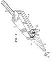
- Fig. 2 shows an isometric view of the NDIR spectrometer.
- the compact construction of this embodiment is clear from this drawing.
- the analysis chambers are built into a block of aluminum 21.
- the 13CO 2 chambers 22, both sample and reference, are considerably longer than the 12CO 2 chambers 23 as explained above.
- the four absorption chambers sample and reference for each of the two isotopes are visible in the end plate 24 of the analyzer block.
- a thin steel shutter 25 slides along a thin recess in the end plate for switching the measurement between the reference channel and the sample gas channel. This is done approximately every 10 to 60 sec., depending on the measurement situation encountered.
- the axes of the isotope lamps 26 and the absorption chambers 22, 23 are aligned such that the output light beams from the four channels are all directed into the single detector 28 by means of the light cone 27.
- Fig. 3 shows an exploded cut-away view of the spectrometer shown in Fig. 1 and Fig. 2.
- the chamber block 30, isotope lamps 31 32, shutter 33, light cone 37 and the detector cover 34 are shown.
- the gas inlet 35 and outlet 36 to the sample chamber are positioned in the side of the block, and the gases led to their respective chambers by means of internal passages drilled into the aluminum block.
- Fig. 4 shows a cut-away cross section of the absorption chambers of the NDIR spectrometer shown in Figs. 1 to 3.
- the two reference absorption chambers 41 42 are connected together pneumatically by means of a tube 43, so that the two reference channels contain the same gas at the same pressure.
- the sample absorption chambers 44 45 are similarly connected by means of tube 46.
- both the 13CO 2 and the 12CO 2 channels of the NDIR spectrometer are thermally strapped together by means of a thick shunt of conductive metal 47, such that the gases in both isotopic channels are thermally as close as possible to being in equilibrium. This feature assists in attaining good thermal stability to the measuring system.
- the reference and sample chambers can be filled with a flowing gas or a static filling, or any combination thereof.
- the reference gas can be a gas mixture with a known isotopic ratio, or if more convenient, a sample of the first breath in the case of a breath analyzer.
- the optical fibers 48 which monitor the lamp 49 intensities are located such that they do not interfere with the entry of the lamp light to the analysis chambers.
- Fig. 5 shows the materials and method of construction of NDIR spectrometer absorption chambers according to a preferred embodiment of the present invention.
- the materials have been selected to provide compactness with high strength and low cost construction.
- the absorption chambers are constructed of an extruded section of a pair of stainless steel tubes 52. Electro-formed light pipes could also be used instead of stainless steel tubes.
- the whole assembly, with the fiber optical monitor fibers 54, is mounted inside a light aluminum profile structure 56, which provides mechanical stability together with low cost and low weight.
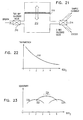
- Fig: 6 is a view taken from the front of the gas channels, showing the 13CO 2 filter 62 located in front of the 13CO 2 gas channels, and the 12CO 2 filter 64 located in front of the 12CO 2 channels. These filters function to remove unnecessary emission regions from the lamp, and to prevent thermal background emission from reaching the detector.
- a high sensitivity differential pressure sensor 66 is connected between reference and sample channels. It is used to ensure that the pressure in the reference and sample channels, both being at a pressure lower than atmospheric, are equated, if advantageous for the measurement.
- the reference channel also includes an absolute pressure sensor, for monitoring the attainment of the reduced pressure required to achieve good measurement sensitivity.
- Fig. 7 illustrates how the shutter 72 is used to select the measurement channel in use.
- the shutter is in the lower position, thereby allowing the lamps to illuminate the reference channels, and to obtain a baseline reference measurement.
- This measurement is a monitor to environmental changes taking place in the system, changes in the lamp light spectrum, changes in filter characteristics, or in detectors or electronics characteristics, all of which should be fairly constant. If the reference measurement does show change, a correction factor is used to compensate the sample channel readings for the change in environmental conditions.
- the shutter is moved up into the position shown in the drawing, and the sample measurement taken from the sample channels. Once this sample measurement has been obtained with sufficient accuracy, the sample is removed pneumatically, and the analyzer ready for receiving its next measurement sample. The chamber purging and the conditioning of the next sample is executed during the reference measurement. This is performed approximately once per minute.
- Fig. 8 is a schematic view of the electronic method whereby signals from the four absorption channels can be discriminated.
- the 13CO 2 lamp is modulated at frequency ⁇ 1, while the 12CO 2 lamp is modulated at frequency ⁇ 2.
- Each channel, sample and zero reference, has its own detector 82 84 respectively.
- Four synchronous detection channels 86 using devices such as lock-in amplifiers, digital signal processors, software packages, or analog or digital filters, are required to extract the four modulated signals from the sample and reference channels of the two isotopic lamps.
- the trigger signals for each of these lock-in amplifiers is taken from the driver signals of the lamp source modulation power supply. Modulation frequencies are in the range of 1 to 200 Hz, with 70 Hz. being a typical value.
- Fig. 10A represents the continuous stream of square wave pulses, which are alternately directed to the 13CO 2 lamp or the 12CO 2 lamp, as shown in Figs. 10B and 10C respectively.
- These pulse trains are convoluted with the output signals from the detector, and the resulting outputs are respectively a train of 13CO 2 pulses as shown in Fig. 10D, or a train of 12CO 2 pulses as shown in Fig. 10E.
- the convolution is performed by a box-car integrator, or a phase sensitive detector.
- FIG. 11 A further preferred embodiment of the present invention is shown in Fig. 11.
- two lamps are used, one for each isotope 112 114.
- Each isotope has its own complete measuring system, with sample, reference and calibration channels, connected only by means of the mechanical, thermal and pneumatic connections as previously described.
- one detector is used for all three signals in each isotope measurement channel.
- a mechanical chopper 116 is used. The chopper can differentiate between the three channels either by means of frequency discrimination, or by means of phase discrimination.
- the chopper has three sets of holes, each set at a different radial distance from the center, and each set having a different number of holes. In this way, three different frequencies for different spatial regions of the source lamp are defined, where these three regions correspond to the three different channels.
- the chopper has three rows of slots, each at different radial distance corresponding to the location of the three channels, and with the sets of slots arranged at fixed angular intervals around the chopper.
- a chopper for use in phase discrimination is shown in Fig. 12.
- the signal received at the detector of either isotope channel when using such a chopper is shown as a function of time.
- phase discrimination choppers there are a number of disadvantages of frequency discrimination choppers when compared to phase discrimination choppers.
- the first problem is that it is very difficult to provide phase sensitive signal processing with a sufficiently high selectivity for the discrimination required by the present system. If the selectivity of the phase sensitive signal processing is insufficient, enough of the signal of the unwanted frequency will be detected to render the measurement inaccurate. In order to provide good detection accuracy for the 13CO 2 in the sample breath, a selectivity of 1 : 20,000 is required, which is difficult to achieve.
- an electronic cross sensitivity effect is present in the detectors, which may have a non-linear response at the upper and lower extremities of their range. Therefore, if a strong signal is present at one frequency, it may shift the operating point of the detector in such a way that it behaves non-linearly to a weak signal of a different frequency imposed upon it. This would severely affect the measurement accuracy.
- phase discrimination choppers Only one channel can be open at any one time, unlike frequency discrimination choppers, wherein all the channels can be transmissive at any time, all being at different frequencies. Consequently, the phase discrimination method has a lower duty ratio, and therefore a less sensitive detection capability.
- Both of the above embodiments according to the present invention use two lamps, and calibration detectors are used to eliminate the effects of source lamp variation, as described above.
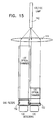
- Fig. 14 and 15 show preferred embodiments of an NDIR spectrometer constructed and operative according to a preferred embodiment of the present invention, wherein only one lamp source is used.
- the lamp 142 is filled with a mixture of the two isotopes whose ratio is to be measured, in this embodiment 13CO 2 and 12CO 2 . Since only one lamp is being used, changes in operating conditions or environmental effects, take place in both channels simultaneously, and therefore have greatly reduced effects on the measurement accuracy.
- the light from the lamp source of the NDIR spectrometer is collected and collimated into two separate beams by means of an entry lens 144. Each beam then passes through its relevant absorption chambers, and via the wavelength filters 146 to the detectors.
- optical interference filters are used for filtering out the unwanted spectral lines from the light in each isotope channel, while in Fig. 15, gas filters 152 are used.
- gas filters 152 are used.
- a combination of gas and optical filters can be used.
- Signal modulation is performed using a mechanical chopper operating either in the frequency or the phase chopping mode, or by means of modulating the lamp and synchronously detecting the signal on each detector separately, while switching between the reference and sample channels by means of a shutter.
- FIG. 16 A further embodiment of the present invention is shown in Fig. 16.
- a further reduction in the sensitivity of the system to external and environmental conditions is achieved by the use of only one detector 162 for both isotope channels, instead of the two used in all of the previous embodiments.
- the one lamp - one detector embodiment represents the system with the best environmental stability with respect to component drift.
- light valves may be used in gas absorption measurements wherein a light source cannot be modulated internally or cannot be modulated fast enough, or wherein more than one channel is viewed by one detector, or wherein the number of channels monitored is larger than the number of detectors.
- discrimination between the signals from the five separate channels - two reference, two sample and one lamp level calibration signal is achieved by means of an SLM, a spatial light modulator 164.
- a spatial light modulator can preferably be a liquid crystal matrix placed between polarizers, or a DMD (Digital Mirror Device) pixelated mirror, such as those produced by Texas Instruments Inc.
- the function of the spatial light modulator is to modulate the light from each channel at a different phase or frequency, according to a predetermined sequence and frequency. This sequence and frequency is conveyed to the phase sensitive detector used to discriminate between the various signals, in order to extract the signal information relevant to each measurement channel.
- the SLM can be operated at high frequency, thereby reducing the noise contribution to the signal.
- Fig. 17 illustrates a preferred embodiment of such an SLM, using transmission liquid crystal elements 172.
- the light from the reference and sample chambers for each isotope channel is passed through a polarizer 174, where it attains a linear direction of polarization. If a particular liquid crystal element 172 is activated, the light passing through that element will attain a polarization switched by a further 90°, so that on passage through another polarizing element 176, the light is cut off. In this way, each liquid crystal element acts as a fast electrically operated switch.
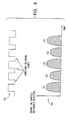
- Fig. 18 is a schematic example of such a chopper.
- Each row of holes 182 is located at a radius from the center such that each row falls exactly on the location 184 of one of the five optical signal channels, labeled ⁇ 1 to ⁇ 5.
- the optical signal channels are shown schematically in one straight line for simplicity, whereas in a real embodiment, they will be staggered to fall in their correct geometrical location in the NDIR spectrometer.
- the frequencies are chosen such that there are no low order common harmonics between them, and the further apart the frequencies, the better the discrimination.
- the system may be constructed to generate a phase difference as in Fig. 12.
- Fig. 19 and 20 show two alternative preferred embodiments for ensuring that the partial pressure of the CO 2 in the sample chamber and the reference chamber are close, in order to ensure that the 13CO 2 absorption is measured accurately and under close conditions in both chambers.
- the embodiments described are of a breath test analyzer application, this being one of the common uses of isotopic gaseous analysis of CO 2 , but the construction and methods shown are applicable to any isotopic gas analysis.
- the sample breaths are exhaled into a reservoir 192, which is connected to the sample absorption measurement chamber by means of a membrane 194 permeable to CO 2 .
- the sample chamber 196 is initially filled with an inert background gas such as pure nitrogen at atmospheric pressure.
- the reference chamber 198 is filled either with the first breath sample, or with a predetermined reference gas mixture.
- the CO 2 from the reservoir diffuses into the sample chamber until the 12CO 2 partial pressure as determined by the 12CO 2 absorption measurement itself, is equal in the sample and reference chambers.
- the membrane passage is sealed off by valving means, and the 13CO 2 measurement is performed accurately in the knowledge that the same conditions exist in the sample and reference chambers.
- Fig. 20 illustrates another preferred embodiment in which the partial pressure of the 12CO 2 in the sample chamber and the reference chamber are equalized.
- the sample breaths are exhaled into a reservoir 200.
- This reservoir is connected by means of a pump 202 to the sample chamber 204, which, unlike the embodiment of Fig. 19, is initially evacuated.
- the pump is operated until the 12CO 2 partial pressures, as determined by the 12CO 2 absorption measurement itself, in the sample and reference chambers are close to each other. When this point is reached, the pump is turned off, and the 13CO 2 measurement is performed accurately in the knowledge that close conditions exist in the sample and reference 206 chambers.
- the condition of equal absorption is also monitored by means of an absolute 209 and a differential pressure measurement gauge 208.
- the pressure measurement is required to correct for changes in the extinction coefficient ⁇ with pressure. As a result of these changes, the same absorption is obtained at different partial pressures. This procedure is likely to result in incorrect isotopic ratio measurements, unless an appropriate correction is applied, which has to be determined by control experiments.
- FIG. 20B illustrates the sample chambers 222, 224 and reference chambers 220, 226 for each of the isotopes, with variable length configurations 228 added to the sample chambers for each isotope.
- Fig. 21 shows the gas handling equipment used in a preferred embodiment of the present invention in order to ensure that the sample reservoir is maintained at a constant pressure while sample gas is being accumulated or pumped into the testing chamber. Entry of breath is permitted by opening of the one-way solenoid valve 210.
- the sample reservoir 212 is fitted with a piston 216, open on its other side to atmospheric pressure, such that the reservoir fills up naturally.
- the two-way solenoid valve 214 is used to enable the accumulated sample to be pumped into the sample chamber. When this takes place, the piston falls, maintaining constant pressure in the vacated volume, such that no vacuum is formed.
- a reservoir in the embodiments shown in Figs. 19 to 21, allows the analyzer to perform sampling of the exhaled breathes in such a way as to substantially increase the reliability of the measurement procedure.
- exhaled breath follows a characteristic CO 2 wave front, whereby there is an initial steep rise in the CO 2 concentration of each exhaled breath, until a slowly rising plateau is reached. At the end of the breath, the volume falls rapidly again to a very low residual level.
- the detection of the exhalation can be performed optically by following changes in the optical absorption of the exhaled gas, or by monitoring changes in the exhalation dynamic pressure.
- the use of such a sampling reservoir allows the analyzer to take an average of several breaths, instead of relying on a single breath sample, which could be atypical of the mean breath of the patient.
- the partial pressures of the various components of exhaled breath vary from breath to breath in a random manner, and averaging is therefore a very important procedure to ensure accurate measurements.
- the patient exhales a number of breaths freely into the reservoir. From the reservoir, the analyzer draws an averaged sample for measurement once measurement of the previous sample has been completed.
- This embodiment has a number of additional advantages. Firstly, the patient is non-functional in the sampling process, and simply breathes at his natural rate into the breath tube, or via a nasal canulla.
- the inlet valving of the analyzer ensures that the correct sample is taken for measurement.
- the breath is allowed to stand, which ensures good temperature and pressure conditioning with respect to the environment.
- the sampling from the reservoir is performed at an approximately fixed partial pressure, such that the measurement is less sensitive to environmental and lamp emission changes, and to cross sensitivity.
- Figs. 19 to 21 illustrate embodiments of reservoirs which provide a certain increase in the level of accuracy attainable in such instruments. In order to further increase the measurement accuracy, it is necessary to incorporate more advanced techniques, which will be described in the following preferred embodiments of the present invention.
- Fig. 22 shows a graph of the infra-red transmission of the 12 CO 2 gas in the sample chamber as a function of its concentration.
- This curve 310 is commonly called the "absorption curve", even though the abscissa shows the gas transmission.
- the curve has an exponential form, where the constant of the exponent, ⁇ , varies somewhat with the environmental conditions of the gas itself.
- Fig. 23 shows the change in cell sensitivity as a function of concentration for analysis chambers with three different cell lengths, marked 320, 322 and 324.
- a cell length is selected which provides maximum overall sensitivity together with minimum dependence of sensistivity on gas concentration in the region of the desired gas concentration of 3 to 4%.
- the cell length shown by curve 322 is optimum, since at 3 to 4% concentration, it has a region of fairly constant sensitivity 26 at its maximum sensitivity.
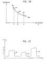
- Fig. 24 is similar to the simple absorption curve shown in Fig. 22, but includes further detail to illustrate the problems which arise when absorption measurements are made at widely different partial pressures.
- the extinction coefficient, ⁇ which characterizes the absorption curve as defined by equation (1) in the background section, is not strictly a constant, but varies somewhat with such factors as the sample gas pressure and temperature, the excitation lamp gas pressure and temperature (if the gas analyzer uses an isotope-specific source lamp of the type described in U.S. Patent No. 4,755,675), the ambient humidity, and cross sensitivity effects with other gases present in the sample.
- the use of an intermediate chamber to ensure that all points measured are close in concentration to each other enables higher accuracies to be achieved.
- the difference in percentage is 1%
- the actual values obtained by the absorption measurement are say 4.3% and 5.5%
- the apparent difference between the two concentration ratios is 1.2%, instead of 1%.
- the operating conditions of the spectrometer such as measurement cell pressure and length, are chosen such that measurements are made in the region of points on the absorption curve such as 334, 336, rather than points such as 338, 340. Under these conditions, the sensitivity of the instrument to environmental changes in the absorption curve is lower, and at the same time, the absolute sensitivity of the transmission to changes in gas concentration is higher.
- Fig. 25A and Fig. 25B illustrate a correction mechanism used for increasing measurement accuracy, by constraining the operating conditions to remain in the region of what is known as the anchor point of the curve.
- the absorption curve 350 shown is for the gas in the reference cell, which contains a fixed and known percentage of the reference gas, typically chosen in the region of 3%.
- the calibration of the instrument is such that a transmission level T1 is measured. Because of the above-mentioned environmental effects, this known concentration results in an actually measured transmission of T2.
- the instrument uses a shifted absorption curve for calculating concentration, so that the readings in the region of 3.5% concentration are corrected by an amount (T1-T2).
- Fig 25B shows an enlarged view of the area 354 around the reference gas concentration point, showing the original absorption curve 350 and the linearly shifted absorption curve 356.
- the anchor point of operation By maintaining the gas concentration close to this reference concentration, which is known as the anchor point of operation, the correction for environmental changes can be made very accurately.
- a range of concentration of 2.8% to 3.2% is shown as the permitted region around the anchor point.
- the transmission T is the exactly corrected value.
- any transmission innaccuracy is limited to small corrections ⁇ T1 and ⁇ T2 respectively.
- skew correction Even after constraining operation to around the anchor point, a further correction may be performed on the reference gas absorption curve, known as skew correction. This correction is illustrated in Fig. 26. After applying the lateral shift correction to the absorption curve, skew correction introduces an angular rotation 360 to the curve around the anchor point 358, thereby almost completely eliminating the residual ⁇ T1 and ⁇ T2 innaccuracies arising from the small angular disparity between the corrected and original absorption curves.
- Fig. 27 shows a representation of a train of breaths, as exhaled from a patient whose breath is to be tested in an isotopic gas analyzer according to the present invention.
- the figure shows how the percentage of carbon dioxide in the breath can vary from breath to breath as a function of time.
- each breath has a different average CO 2 percentage concentration, where the term concentration is used to mean the average plateau concentration level.
- the first breath shown 370 has a concentration of 3% CO 2
- the second one 372 has 1.5%
- the third one 374 has 5%.
- the simple averaging function of the intermediate chamber is supplemented by the addition of pneumatic control elements, which perform two additional functions. Firstly, they determine which part or parts of each breath wave are to be accumulated in order to achieve the preferred accumulated sample gas concentration for optimum measurement sensitivity. Secondly, they perform the dilution of the accumulated sample gas, if found necessary, when the sample has a concentration above the optimum. As a result, a sample of very closely controlled concentration is obtained.
- Fig. 28 shows a time plot of a typical breath wave 380, with its constituent parts.
- the wave begins with a slow rise of the CO 2 signal to reference ratio 382, to the "threshold start" point 384, usually defined as the point at which the ratio reaches a level of 10% .
- This region is characterized by a very low level of CO 2 , and it is therefore known as Region 0, or the baseline region.
- Region 1 There then follows a slope with rapid rise of CO 2 content towards the plateau 388, terminating at a point known as the "threshold up” 386, when the CO 2 concentration ratio reaches 90%. This is known as Region 1.
- the time taken for this region is typically 50 to 100 msec.
- the plateau itself 388 is known as Region 2, and the slope from the "threshold down” point 390 to the "threshold end” point 392, is Region 3. Beyond the "threshold end” point, there is another baseline Region 0, bereft of CO 2 until the commencement of the next breath.
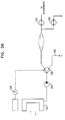
- Fig. 29 is a schematic representation of a breath test system according to the present invention, to illustrate the operation of such an intermediate chamber system.
- the patient 400 undergoing the test breathes or blows into the nasal or oral cannula 402.
- the breath samples are inputted to a breath sensor module 404, whose function is to monitor the individual input sample breaths.
- a controlled two-way solenoid valve 406 is operative to direct the sample gas from the breath sensor module either into an accumulation bag 410, or if unneeded, out into the room area.
- the sample gas is passed periodically to the NDIR spectrometric measurement cell 412, for measurement of the ratio of 13 CO 2 / 12 CO 2 in the sample tested.
- a computer 408 receives and processes the results of the measurements and of all the parameters measured in the system, and accordingly controls the operation of the whole intermediate chamber system.
- the breath sensor module contains a fast carbon dioxide probe for monitoring the wave of the breath inputted from the patient. The speed of this probe is such that it can differentiate between the different regions of the waveform shown in Fig. 28.
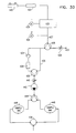
- Fig. 30 illustrates a preferred embodiment of the gas handling system of a carbon dioxide breath test system based on an isotopic gas analyzer incorporating an intermediate chamber system, constructed and operative according to the present invention.
- Samples of the breath of the subject are collected by means of the nasal cannula 420, though an oral breath collection tube could equally well be utilized for the purpose.
- the breaths are then passed through a filter line 422 to reduce moisture content.
- a fast CO 2 probe 424 is located immediately following the filter line, in order to dynamically monitor the carbon dioxide concentration in the breath waves inputted to the system.
- the response time of this CO 2 probe should be as short as possible, and according to a preferred embodiment of the present invention, is 50 msec. or less.
- the temperature and pressure of the inputted breath samples are measured by means of probes 425, 426, and the results used for applying environmental condition corrections to the absorption curve.
- the pressure monitor 426 also gives warning of system blockages.
- the sample breaths then pass along a tube 427 of a predefined length to the two-way solenoid valve 428.
- This solenoid valve is the first decision-based operation performed on the breath samples, and it determines at what points in time the sample gas is allowed to continue into the system for accumulation and measurement, and at what points in time it is unneeded, and is ejected to the atmosphere.
- the decision and its timing are based on an estimate of the 12 CO 2 concentration in the accumulated gas, as determined from the results of the previous accumulated points, and from the instantaneous level of 12 CO 2 concentration in the breathwave passing, as determined by the dynamic CO 2 probe measurements. The criteria for this decision are discussed hereinunder, in conjunction with the software flow chart shown in Fig. 10.
- the tube 427 must not be shorter than a certain minimum length in order to provide decision time for the results of the CO 2 probe measurement to be received by the time the gas sample reaches the solenoid valve.
- the minimum tube length is determined by the flow speed of the gas sample and the response time of the CO 2 probe.
- the tube should not be longer than necessary in order to avoid the possibility of missing collection of part of the gas because of flow rate dispersion.
- the ejected gas passes through a variable restrictor valve 430 and is then ejected into the atmosphere by means of an exhauster pump, or any alternative evacuation means 433.
- the sample gas passed by solenoid valve 428 into the system can proceed in one of two alternative paths, according to the setting of solenoid valve 438. In one path 435, the gas proceeds directly to the solenoid valve 438 without any processing.
- the gas in the second path traverses a check valve 434, to prevent reverse flow in that path, and then passes through a carbon dioxide scrubber 436, which effectively removes any CO 2 in the gas stream. If the breath test is being performed to detect isotopic ratios in an alternative gas, then the CO 2 scrubber 436 is replaced by an absorption unit specific for that alternative gas.
- the criteria for the decision as to the path into which the gas is directed by the solenoid valve are discussed hereinunder, in conjunction with the flow chart shown in Fig. 31.
- the selected gas is then drawn through the restrictor 440 by means of pump 442 to solenoid valve 444, for the next operative decision.
- the pump 442 together with evacuation means 433 in the ejection line, provide a flow of sample gas from the cannula, regardless as to whether a patient is attached or not. Even when attached, the pumps provide a flow regardless of how he breathes, or how he blows if connected to an oral sampling tube.
- check valve 434 effectively isolates the scrubber at its input end, and prevents its contents from flowing back through the direct path 435 when the solenoid has cut off flow through the scrubber.
- An additional reason for the location of solenoid 138 is that the dead space and air mixing effects present therein would otherwise result in innacuracies.
- Restrictor valves 430 and 440 are adjusted to ensure a steady and approximately equal flow of gas in both the sampling and the ejection paths. In this way, switching over of solenoid 428 does not disrupt the even gas flow in the system.
- the two-way solenoid valve 444 is operative for alternating between gas collection in one sample bag 446 or the other 448. In this way, while the accumulated contents of one sample bag are being measured for isotopic ratio, the sample gas can continue to be collected in the second bag, thereby increasing the measurement rate of the instrument.
- the contents of each sample bag are allowed to flow via the two-way solenoid valve 454, to the isotope ratio measurement instrument 156.
- Solenoid valve 454 is operated in anti-phase to solenoid valve 444, such that when valve 444 is directing collected sample gas into bag 446, only the contents of bag 448 can be transferred for measurement, and vice versa.
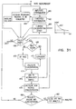
- Fig. 31 shows the flow chart for the software controlling the dynamic sample collection process. This gas handling and preprocessing cycle is based on two initial assumptions regarding the collection procedure:
- the amplitude level of the plateau and the baseline are calculated, by checking back over the past accumulated points for the minimum and maximum amplitudes of the absorption points measured by the CO 2 probe.
- the amplitude is defined as the range between these maximum and minimum values, and the thresholds are determined in relation to this amplitude.
- a knowledge of the amplitude level is important to in order to compensate for changes in the thresholds if changes in the breath pattern occur for any reason as the test proceeds.
- the threshold levels for defining the different regions of each breath wave are calculated in step 462, and these defined levels are applied to each breath in step 464.
- step 466 The decision taken in step 466, as to whether the sample should be collected or not, and if collected, which parts thereof, is dependent on a three inputted factors:
- a decision based on these three inputs is taken, regarding the conditioning of the next sample breath,. If the current concentration is higher than the target concentration, a decision is taken to collect gas also from the slope and even the baseline regions. If the current concentration is lower than the target concentration, gas is collected only from the plateau region, and gas from the other regions is ejected to the atmosphere. If the final volume of gas has already been collected, and the concentration is higher than the target concentration, only scrubbed gas from the baseline regions is collected, until the required dilution has been obtained.
- the concentration of CO 2 is calculated, and at step 476, the sample counter is increased by one point, to represent the last sample added to the bag.
- This counter is used to determine when 150 points have been added, which represents the full state of the sample bag undergoing the filling.
- the points added immediately after the opening of solenoid valve 428, and to a lesser extent 438, of Fig. 30 may be weighted, since, when a solenoid is switched, the gas flow is interrupted, and the flow rate may decrease temporarily.
- the first breaths collected after a solenoid valve switch are thus likely to be more dilute, and each point is given less weighting in the averaging calculation. This weighting is done both in the percentage concentration calculation and in the counter for estimating the volume of gas collected.
- Point weighting is also used if the pressure reading on the gauge 426 indicates that there is a reduction in flow, for instance because of a partial blockage.
- the new concentration is calculated from the average of all the inputted breath samples after the addition of the last breath or parts thereof, and the concentration value updated, for use as a decision making input in step 466 regarding what part of the next sample to collect, and for updating the target concentration 480.
- step 480 the collected volume and concentration are checked, and if both have reached their target values, the collection process for that particular sample bag is terminated, and the bag is made available for analysis. If not, the process returns to step 160, and sample collection is continued.
- the intermediate chamber system incorporates an inherent self-calibration facility, without the need for operator intervention, which ensures continued accuracy for very long periods of use.
- the CO 2 probe measurement at the entrance to the system provides a measure of the CO 2 concentration, on the basis of which, the content of the bag at the end of the filling process is estimated. The accuracy of this measurement is dependent on a knowledge of the exact absorption curve, which may have changed because of operating conditions.
- This measurement can be compared with the integrated measurement of the isotopic ratio obtained from the complete gas analyzer system.
- the isotopic ratio measurement is highly accurate by virtue of the reference gas comparison measurement, and the other facilities built into the instrument. Any deviation of the two measurements can then be used to correct the absorption curve for the actual environmental conditions existent in the system. This is done by correcting the CO 2 probe calibration, so that the estimated bag concentration is made equal to the measured concentration.
- the sample is diluted down using the intermediate chamber system to lower values, such as to 4.5%, 4%, 3.5% and so on.
- Each of these diluted samples is then also measured in the gas analyzer for isotopic ratio, and since each sample was derived from the same original breath sample, there should be no change in the isotopic ratio. Any change detected is indicative of a shift in the absorption curve, and the calibration can be adjusted accordingly to bring the readings back into agreement.
- a further self-calibration facility is available, according to another preferred embodiment of the present invention, by observing the correlation of the noise level in the isotopic ratio measurements obtained from negative subjects, with the CO 2 concentration measurements obtained from the same subjects.
- the procedure operates in the following manner. Breath samples are observed from a large range of negative subjects. In effect, the system can continually observe measurements obtained from negative patients to execute this procedure, and does not need any co-operation on the part of patients or staff. Each of these samples may have different levels of CO 2 concentration, and in this respect, the method is similar to the previous method described wherein a single negative sample is repeatedly diluted down in the intermediate chamber system to obtain multiple samples with different CO 2 concentrations.
- This facility can be in operation all the time, and can therefore maintain a constant state of recalibration in the gas analyzer. Furthermore, it should be noted that this method can be applied to any gas analyzer, whether fitted with an intermediate chamber system or not.
- Fig. 32 to Fig. 34 show various preferred embodiments of a breath'intake device incorporating mechanical check valve assemblies, which open at predetermined air flows such that preselected parts or all of a number of the patient's exhaled breaths are collected in the intermediate chamber.
- Fig. 32 shows a mechanical check valve assembly 500 incorporating a reservoir with constant volume 502, for providing a constant sampling flow rate.
- the patient inserts the mouthpiece 504 into his mouth and breaths normally into the device. Inhaled air is sucked in through the check valve 506. Exhaled air passes into the body of the breath intake device, and closes the input check valve 506, so that the exhaled air is contained within the input chamber 508.
- This gas passes into the reservoir 502 through the opening 512, and the filter element 516, whose function is to clean the air, to smooth out any pulsations arising from individual breaths, and to distribute the exhaled air throughout the whole of the outer volume 502.
- a restrictor valve R1 514 is used to set the level of gas flow permitted through the check valve 510.
- This outer part of the reservoir is fitted with a further check valve 520, which opens as soon as a slight overpressure indicates the presence of sample gas in the reservoir.
- a restrictor valve R2 522 is used to set the level of gas flow permitted through the check valve 520.
- the flow rate through R2 is much smaller than that through R1, such that most of the exhaled breath passes through R1 to the outside air, and only a small sample is passed into the reservoir on its way out through R2.
- the ratio of restrictors R2/R1, known as N determines the number of breaths required to fill the reservoir.
- N the bypass ratio
- valve 524 when the reservoir volume has been filled by the determined number of breaths, the valve 524 is opened, and the sample accumulated in the reservoir from an average of the patient's breaths, is conveyed by means of tube 518 to the analyzer chamber for measurement.
- valve 524 is open continuously, or is not even present, and the device is used as a continuous breath monitoring system.
- Fig. 33 shows another intermediate chamber breath sampling device, constructed and operated according to a further embodiment of the present invention.
- This mechanical check valve assembly 530 is similar to that shown in Fig. 32, except that it incorporates a reservoir with a variable volume 532, for providing a system for use with a variable sampling flow rate.
- the reservoir can be provided with flexible walls 534, which expand and contract during exhalation and inhalation.
- the other details of this embodiment are as marked in Fig. 32.
- Fig. 34 shows a double reservoir intermediate chamber breath sampling device, constructed and operated according to a further embodiment of the present invention.
- This mechanical check valve assembly 530 is similar to that shown in Fig. 32, but the rigid reservoir has no outlet tube for conveying the accumulated averaged gas to the analyzing chamber. Instead, the reservoir output check valve 540 leads the accumulated gas into a second reservoir 542, which has flexible sides, like that in Fig. 33.
- the flow of gas into the second reservoir is controlled by the flow rate out of the second reservoir through the restrictor R2 544.
- the second reservoir When the second reservoir is full, its accumulated gas is outputted to the analyzing chamber by opening valve 518, as in the previous embodiments.
- the advantages of this double reservoir system are that firstly, it is possible to use standard disposable collection bags as the main collection reservoir, and secondly, the main reservoir can be installed in the instrument, away from the patient, so that the patient interface device becomes much more compact.
- Fig. 35 shows yet another intermediate chamber breath sampling device, constructed and operated according to a further embodiment of the present invention.
- This embodiment is suitable for use with nasal cannula breath sampling, and uses a flow direction sensor, such as a piezoelectric membrane sensor, or a strain gauge sensor, or a similar flow direction sensor.
- a flow direction sensor such as a piezoelectric membrane sensor, or a strain gauge sensor, or a similar flow direction sensor.
- the flow direction sensor 550 is mounted on or near the nasal cannula intakes 552, and provides an AC electronic signal 554 proportional to the flow rate of the exhaled breath.
- the sampled breath from the cannula is drawn by means of pump 556 to switchable solenoid 558. The position of this solenoid is controlled by the signal from the flow direction sensor.
- the gas flowing down the line from the cannula is ejected into the room area 562.
- the solenoid is switched such that the ensuing breath is directed into the intermediate chamber 560, for accumulation.
- the breath wave passes, the gas from the cannula is again rejected, until the rise of the next breath wavefront.
- the intermediate chamber is used to accumulate breath only from the plateau areas of the exhaled breath, ensuring a high CO 2 concentration.
- solenoid 564 is switched, thereby allowing the collected breath sample to flow to the analysis chamber of the instrument for measurement.
- Solenoid 565 is used in order to vent the reservoir 560 speedily when necessary, by contracting its flexible walls with the solenoid valve 565 open to the atmosphere.
- Fig. 36 shows another intermediate chamber breath sampling device, constructed and operated according to a further embodiment of the present invention.
- This embodiment like that shown in Fig. 35, is also suitable for use with nasal cannula breath sampling, but it differs in that instead of using a sensitive flow direction sensor to detect the rise of the breath wave, this embodiment uses a differential pressure sensor, such as a thermoanemometer.
- the component parts of the intermediate chamber system are identical to those in Fig. 35, except that the control signal to the breath sampling solenoid 558 is provided by a differential pressure sensor 570, which detects the slight changes which occur in nasal cannula flow as the patient breathes.
- the electrical signal is more stable, especially for high or non-stable respiration rate applications, such as for neo-natal use.
- the use of a differential pressure sensor enables the comparatively more costly sensor measurement element to be separated from the breath sensing element. The sensor element can thus be installed in the instrument itself, and be connected to the patient by means of a cheap disposable sampling tube attached to the nasal cannula.
Landscapes
- Health & Medical Sciences (AREA)
- Life Sciences & Earth Sciences (AREA)
- Physics & Mathematics (AREA)
- Engineering & Computer Science (AREA)
- Chemical & Material Sciences (AREA)
- General Health & Medical Sciences (AREA)
- Pathology (AREA)
- Biomedical Technology (AREA)
- Molecular Biology (AREA)
- Immunology (AREA)
- Biophysics (AREA)
- General Physics & Mathematics (AREA)
- Biochemistry (AREA)
- Analytical Chemistry (AREA)
- Medicinal Chemistry (AREA)
- Food Science & Technology (AREA)
- Public Health (AREA)
- Veterinary Medicine (AREA)
- Spectroscopy & Molecular Physics (AREA)
- Physiology (AREA)
- Pulmonology (AREA)
- Heart & Thoracic Surgery (AREA)
- Medical Informatics (AREA)
- Surgery (AREA)
- Animal Behavior & Ethology (AREA)
- Urology & Nephrology (AREA)
- Hematology (AREA)
- Emergency Medicine (AREA)
- Obesity (AREA)
- Combustion & Propulsion (AREA)
- Investigating Or Analysing Materials By Optical Means (AREA)
- Investigating Or Analysing Biological Materials (AREA)
- Lock And Its Accessories (AREA)
- Sampling And Sample Adjustment (AREA)
- Other Investigation Or Analysis Of Materials By Electrical Means (AREA)
- Analysing Materials By The Use Of Radiation (AREA)
- Optical Measuring Cells (AREA)
Applications Claiming Priority (3)
| Application Number | Priority Date | Filing Date | Title |
|---|---|---|---|
| IL12179397 | 1997-09-17 | ||
| IL121793A IL121793A (en) | 1997-09-17 | 1997-09-17 | Isotopic gas analyzer |
| EP98945516A EP1012573B1 (de) | 1997-09-17 | 1998-09-17 | Isotopengas-analysator |
Related Parent Applications (1)
| Application Number | Title | Priority Date | Filing Date |
|---|---|---|---|
| EP98945516A Division EP1012573B1 (de) | 1997-09-17 | 1998-09-17 | Isotopengas-analysator |
Publications (2)
| Publication Number | Publication Date |
|---|---|
| EP1211502A2 true EP1211502A2 (de) | 2002-06-05 |
| EP1211502A3 EP1211502A3 (de) | 2004-03-03 |
Family
ID=11070650
Family Applications (3)
| Application Number | Title | Priority Date | Filing Date |
|---|---|---|---|
| EP02004740A Withdrawn EP1211502A3 (de) | 1997-09-17 | 1998-09-17 | Selbstkalibrierender Isotopengas-Analysator |
| EP98945516A Expired - Lifetime EP1012573B1 (de) | 1997-09-17 | 1998-09-17 | Isotopengas-analysator |
| EP02004741A Withdrawn EP1217355A3 (de) | 1997-09-17 | 1998-09-17 | Gasprobenkammer |
Family Applications After (2)
| Application Number | Title | Priority Date | Filing Date |
|---|---|---|---|
| EP98945516A Expired - Lifetime EP1012573B1 (de) | 1997-09-17 | 1998-09-17 | Isotopengas-analysator |
| EP02004741A Withdrawn EP1217355A3 (de) | 1997-09-17 | 1998-09-17 | Gasprobenkammer |
Country Status (8)
| Country | Link |
|---|---|
| US (1) | US7063667B1 (de) |
| EP (3) | EP1211502A3 (de) |
| JP (1) | JP2001516875A (de) |
| AT (1) | ATE288075T1 (de) |
| AU (1) | AU9279498A (de) |
| DE (1) | DE69828799T2 (de) |
| IL (1) | IL121793A (de) |
| WO (1) | WO1999014576A2 (de) |
Cited By (4)
| Publication number | Priority date | Publication date | Assignee | Title |
|---|---|---|---|---|
| WO2007054799A2 (en) * | 2005-11-14 | 2007-05-18 | Schlumberger Technology B.V. | Real-time calibration for downhole spectrometer |
| WO2007107366A1 (de) * | 2006-03-17 | 2007-09-27 | Freie Universität Berlin | Vorrichtung zur spektroskopischen analyse eines gases |
| WO2009082318A1 (en) * | 2007-12-20 | 2009-07-02 | Aerocrine Ab | Method for testing the function of a device |
| US20220307975A1 (en) * | 2021-03-25 | 2022-09-29 | Asahi Kasei Microdevices Corporation | Gas sensor |
Families Citing this family (57)
| Publication number | Priority date | Publication date | Assignee | Title |
|---|---|---|---|---|
| JP4312294B2 (ja) * | 1999-03-26 | 2009-08-12 | 独立行政法人科学技術振興機構 | アイソトポマー吸収分光分析装置及びその方法 |
| IL130371A (en) * | 1999-06-08 | 2004-06-01 | Oridion Medical Ltd | Capnography waveform interpreter |
| JP2003524149A (ja) | 1999-06-08 | 2003-08-12 | オリディオン ブレシド リミティド | ガス分析器検定試験装置 |
| US6656127B1 (en) | 1999-06-08 | 2003-12-02 | Oridion Breathid Ltd. | Breath test apparatus and methods |
| US6486474B1 (en) * | 1999-08-13 | 2002-11-26 | Regents Of The University Of Minnesota | Infrared spectrometer for the measurement of isotopic ratios |
| DE19962588A1 (de) * | 1999-12-23 | 2001-07-05 | Abb Patent Gmbh | Verfahren und Einrichtung zur Kalibrierung einer Messeinrichtung |
| JP4860879B2 (ja) * | 2000-04-04 | 2012-01-25 | オリディオン ブレシド リミティド | 呼気検査装置および方法 |
| DE10062126A1 (de) * | 2000-12-13 | 2002-06-20 | Inficon Gmbh | Verfahren zur Feststellung eines Gases mit Hilfe eines Infrarot-Gasanlaysators sowie für die Durchführung dieser Verfahren geigneter Gasanalysator |
| US8144671B2 (en) | 2005-07-01 | 2012-03-27 | Twitchell Jr Robert W | Communicating via nondeterministic and deterministic network routing |
| IL148468A (en) | 2002-03-03 | 2012-12-31 | Exalenz Bioscience Ltd | Breath collection system |
| US7338444B2 (en) * | 2002-06-28 | 2008-03-04 | Oridion Breathid Ltd | Management of gastro-intestinal disorders |
| WO2005006988A1 (en) | 2003-06-19 | 2005-01-27 | Everest Biomedical Instruments | Breath end-tidal gas monitor |
| US7142107B2 (en) | 2004-05-27 | 2006-11-28 | Lawrence Kates | Wireless sensor unit |
| JP5583340B2 (ja) * | 2005-04-18 | 2014-09-03 | ガスポロックス エイビー | 体内腔部ガス測定装置及び測定方法 |
| DE102005025675A1 (de) * | 2005-06-03 | 2006-11-16 | Siemens Ag | Strahleranordnung für einen nichtdispersiven Infrarot-Gasanalysator |
| ES2668293T3 (es) * | 2006-02-03 | 2018-05-17 | Otsuka Pharmaceutical Co., Ltd. | Método de medición y análisis de gas exhalado y aparato para el mismo |
| WO2007130923A2 (en) * | 2006-05-01 | 2007-11-15 | Cellerant Therapeutics, Inc. | Portable platform cytometric system with isolation chamber |
| US7570360B1 (en) * | 2007-02-01 | 2009-08-04 | Bah Holdings, Llc | Optical absorption spectrometer and method for measuring concentration of a substance |
| US7796265B2 (en) * | 2008-04-24 | 2010-09-14 | Bah Holdings Llc | Optical absorption gas analyser |
| WO2009151877A2 (en) | 2008-05-16 | 2009-12-17 | Terahop Networks, Inc. | Systems and apparatus for securing a container |
| DE102009021829A1 (de) * | 2009-05-19 | 2010-11-25 | Siemens Aktiengesellschaft | NDIR-Zweistrahl-Gasanalysator und Verfahren zur Bestimmung der Konzentration einer Messgaskomponente in einem Gasgemisch mittels eines solchen Gasanalysators |
| WO2011102316A1 (ja) * | 2010-02-16 | 2011-08-25 | 浜松ホトニクス株式会社 | ガス濃度算出装置及びガス濃度計測モジュール |
| DE102010030549B4 (de) | 2010-06-25 | 2016-04-28 | Siemens Aktiengesellschaft | Nichtdispersiver Gasanalysator |
| US8692997B2 (en) | 2010-08-25 | 2014-04-08 | Bah Holdings Llc | Optical gas and/or particulate sensors |
| US8415626B1 (en) * | 2010-08-25 | 2013-04-09 | Airware, Inc. | Intrinsically safe NDIR gas sensor in a can |
| US8158946B2 (en) * | 2010-08-25 | 2012-04-17 | Airware, Inc. | Intrinsically safe improved sensitivity NDIR gas sensor in a can |
| US8692202B2 (en) * | 2010-09-23 | 2014-04-08 | Li-Cor, Inc. | Gas exchange system flow configuration with thermally insulated sample chamber |
| US8610072B2 (en) | 2010-09-23 | 2013-12-17 | Li-Cor, Inc. | Gas exchange system flow configuration |
| EP2619549B1 (de) | 2010-09-23 | 2018-03-21 | Li-Cor, Inc. | Strömungskonfiguration für ein gasaustauschsystem |
| US20120181432A1 (en) * | 2011-01-13 | 2012-07-19 | Li-Cor, Inc. | Off-set compensation technique for dual analyzer gas exchange systems |
| CN103620382B (zh) * | 2011-04-26 | 2017-07-14 | 皇家飞利浦有限公司 | 用于针对光学气体测量系统来控制辐射源可变性的装置及方法 |
| US9618417B2 (en) * | 2011-10-20 | 2017-04-11 | Picarro, Inc. | Methods for gas leak detection and localization in populated areas using isotope ratio measurements |
| WO2013096695A2 (en) | 2011-12-21 | 2013-06-27 | Capnia, Inc. | Collection and analysis of a volume of exhaled gas with compensation for the frequency of a breathing parameter |
| WO2014110181A1 (en) | 2013-01-08 | 2014-07-17 | Capnia, Inc. | Breath selection for analysis |
| EP2950710A1 (de) * | 2013-01-31 | 2015-12-09 | Universidade do Minho | Optisches system zur charakterisierung von parametern eines elements aus körperflüssigkeit oder gewebe |
| AU2014216297A1 (en) | 2013-02-12 | 2015-09-17 | Capnia, Inc. | Sampling and storage registry device for breath gas analysis |
| US11191449B2 (en) | 2013-08-30 | 2021-12-07 | Capnia, Inc. | Neonatal carbon dioxide measurement system |
| EP3119278B1 (de) * | 2014-03-20 | 2022-02-23 | Capnia, Inc. | Auswahl, segmentierung und analyse von ausgeatmetem atem zur atemwegserkrankungsbeurteilung |
| US10568568B2 (en) | 2014-08-27 | 2020-02-25 | Capnia, Inc. | Methods for immune globulin administration |
| CN106068448A (zh) * | 2014-09-22 | 2016-11-02 | 株式会社东芝 | 呼气诊断装置 |
| WO2016047169A1 (ja) * | 2014-09-22 | 2016-03-31 | 株式会社 東芝 | 呼気診断装置 |
| JP6435799B2 (ja) * | 2014-11-17 | 2018-12-12 | 横河電機株式会社 | 光学装置および測定装置 |
| CN105628637B (zh) * | 2015-12-29 | 2018-12-04 | 山东罗纳德分析仪器有限公司 | 一种三参考通道的红外气体分析方法与装置 |
| JP6647061B2 (ja) * | 2016-02-04 | 2020-02-14 | ホシデン株式会社 | 呼気成分計測装置 |
| EP3206019A1 (de) * | 2016-02-11 | 2017-08-16 | Inficon GmbH | Verfahren zur quantifizierung der menge von optisch interferierenden gasverunreinigungen |
| WO2017189546A1 (en) * | 2016-04-26 | 2017-11-02 | Endo Medical, Inc. | Breath analysis device |
| EP3273152A1 (de) * | 2016-07-11 | 2018-01-24 | bluepoint medical GmbH & Co. KG | Anordnung zum messen von gaskonzentrationen |
| DE102016124068A1 (de) * | 2016-12-12 | 2018-06-14 | HELLA GmbH & Co. KGaA | Messeinrichtung und Verfahren zur Feinstaubmessung für ein Kraftfahrzeug |
| WO2018222764A1 (en) | 2017-05-30 | 2018-12-06 | Analog Devices, Inc. | Compact optical gas detection system and apparatus |
| US10330592B2 (en) | 2017-07-21 | 2019-06-25 | Serguei Koulikov | Laser absorption spectroscopy isotopic gas analyzer |
| US11796445B2 (en) | 2019-05-15 | 2023-10-24 | Analog Devices, Inc. | Optical improvements to compact smoke detectors, systems and apparatus |
| US11747272B2 (en) | 2019-06-10 | 2023-09-05 | Analog Devices, Inc. | Gas detection using differential path length measurement |
| DE102019118171A1 (de) * | 2019-07-04 | 2021-01-07 | Endress+Hauser Conducta Gmbh+Co. Kg | Verfahren zum Betreiben eines automatischen Analysegeräts und ein automatisches Analysegerät |
| US11131628B1 (en) * | 2020-05-12 | 2021-09-28 | Savannah River Nuclear Solutions, Llc | Spectroscopic methods and systems for isotopic analysis |
| US11821836B2 (en) | 2020-07-13 | 2023-11-21 | Analog Devices, Inc. | Fully compensated optical gas sensing system and apparatus |
| US20230009301A1 (en) * | 2021-07-12 | 2023-01-12 | Government Of The United States, As Represented By The Secretary Of The Air Force | Flow Regulation Device for Volatile and Semi-Volatile Sampling Onto Adsorbent Media |
| DE102023106820A1 (de) | 2023-03-17 | 2024-09-19 | Sick Ag | Spektroskopische Analysevorrichtung mit einer Mehrkammerküvette zur Fluid- oder Gasanalyse und entsprechendes Verfahren |
Family Cites Families (32)
| Publication number | Priority date | Publication date | Assignee | Title |
|---|---|---|---|---|
| US3830630A (en) * | 1972-06-21 | 1974-08-20 | Triangle Environment Corp | Apparatus and method for alcoholic breath and other gas analysis |
| US4578762A (en) * | 1983-07-01 | 1986-03-25 | Tri-Med Inc. | Self-calibrating carbon dioxide analyzer |
| US4684805A (en) * | 1985-08-21 | 1987-08-04 | General Motors Corporation | Method and apparatus for measuring stable isotopes |
| IL77494A (en) * | 1986-01-01 | 1989-12-15 | Irad Technologies Ltd | Gas analyzer |
| US4723435A (en) | 1986-03-24 | 1988-02-09 | Research And Education Institute, Inc., Harbor-Ucla Medical Center | Means of controlled simulation of respiratory gas exchange for on-line calibration of respiratory analyzers |
| US4907166A (en) * | 1986-10-17 | 1990-03-06 | Nellcor, Inc. | Multichannel gas analyzer and method of use |
| US5300859A (en) * | 1987-11-12 | 1994-04-05 | Yissum Research Development Company Of The Hebrew University Of Jerusalem | IR-radiation source and method for producing same |
| US5335656A (en) | 1988-04-15 | 1994-08-09 | Salter Laboratories | Method and apparatus for inhalation of treating gas and sampling of exhaled gas for quantitative analysis |
| FI82803C (fi) | 1988-09-02 | 1991-04-25 | Instrumentarium Oy | Foerfarande foer bestaemning av halten av en gaskomponent i en patients andningsluft. |
| JPH02164341A (ja) * | 1988-12-19 | 1990-06-25 | Nippon Koden Corp | ヘモグロビン濃度測定装置 |
| US5046491A (en) | 1990-03-27 | 1991-09-10 | Derrick Steven J | Apparatus and method for respired gas collection and analysis |
| DE4012454C1 (de) | 1990-04-19 | 1991-08-08 | Fraunhofer-Gesellschaft Zur Foerderung Der Angewandten Forschung E.V., 8000 Muenchen, De | |
| US5239492A (en) | 1990-10-11 | 1993-08-24 | Spacelabs Medical, Inc. | Automatic internal calibration circuit and method |
| US5140993A (en) | 1991-12-27 | 1992-08-25 | Baylor College Of Medicine | Device for collecting a breath sample |
| US5553177A (en) | 1992-01-15 | 1996-09-03 | Ceramoptec Industries, Inc. | Optical fiber device which increases light intensity |
| US5317156A (en) | 1992-01-29 | 1994-05-31 | Sri International | Diagnostic tests using near-infrared laser absorption spectroscopy |
| US5394236A (en) * | 1992-02-03 | 1995-02-28 | Rutgers, The State University | Methods and apparatus for isotopic analysis |
| EP0584897B1 (de) | 1992-07-22 | 1996-10-16 | MANNESMANN Aktiengesellschaft | Nichtdispersives Infrarotspektrometer |
| US5303575A (en) | 1993-06-01 | 1994-04-19 | Alcotech Research Inc. | Apparatus and method for conducting an unsupervised blood alcohol content level test |
| EP0634644A1 (de) * | 1993-07-13 | 1995-01-18 | Mic Medical Instrument Corporation | Vorrichtung zur Bestimmung des 13CO2/12CO2-Konzentrationsverhältnisses in einer Gasprobe |
| EP0661583B1 (de) * | 1993-12-28 | 2002-05-08 | Shimadzu Corporation | Lichtmodulator mit dicher Flüssigkristallzelle |
| DE4402054A1 (de) * | 1994-01-25 | 1995-07-27 | Zeiss Carl Fa | Gaslaser und Gasnachweis damit |
| US5543621A (en) | 1995-05-15 | 1996-08-06 | San Jose State University Foundation | Laser diode spectrometer for analyzing the ratio of isotopic species in a substance |
| EP1596183A3 (de) * | 1995-10-09 | 2008-02-20 | Otsuka Pharmaceutical Company, Limited | Verfahren und Vorrichtung zur spektroskopischen Messung eines Isotopengases |
| FI107194B (fi) * | 1996-03-14 | 2001-06-15 | Instrumentarium Oy | Kaasuseosten analysointi infrapunamenetelmällä |
| JP3274605B2 (ja) * | 1996-05-01 | 2002-04-15 | 日本無線株式会社 | 炭素同位体分析装置 |
| US5747809A (en) * | 1996-06-11 | 1998-05-05 | Sri International | NDIR apparatus and method for measuring isotopic ratios in gaseous samples |
| US5957858A (en) * | 1996-07-26 | 1999-09-28 | Polestar Technologies, Inc. | Systems and methods for monitoring relative concentrations of different isotopic forms of a chemical species |
| ATE271218T1 (de) | 1997-01-14 | 2004-07-15 | Otsuka Pharma Co Ltd | Vorrichtung und verfahren zur messung stabiler isotope mittels spektroskopie |
| JP2001514747A (ja) * | 1997-03-11 | 2001-09-11 | フィッシャー・アナリューゼン・インストルメンテ・ゲゼルシャフト・ミト・ベシュレンクテル・ハフツング | 炭素同位体分析計 |
| DE19713636A1 (de) | 1997-04-02 | 1998-10-08 | Pari Gmbh | Atemzugsimulator |
| US6234001B1 (en) | 1999-08-03 | 2001-05-22 | Ian W. Sorensen | Apparatus and method for generating calibration gas |
-
1997
- 1997-09-17 IL IL121793A patent/IL121793A/en not_active IP Right Cessation
-
1998
- 1998-09-17 EP EP02004740A patent/EP1211502A3/de not_active Withdrawn
- 1998-09-17 AT AT98945516T patent/ATE288075T1/de not_active IP Right Cessation
- 1998-09-17 AU AU92794/98A patent/AU9279498A/en not_active Abandoned
- 1998-09-17 WO PCT/IL1998/000458 patent/WO1999014576A2/en active IP Right Grant
- 1998-09-17 US US09/508,805 patent/US7063667B1/en not_active Expired - Lifetime
- 1998-09-17 JP JP2000512066A patent/JP2001516875A/ja active Pending
- 1998-09-17 DE DE69828799T patent/DE69828799T2/de not_active Expired - Lifetime
- 1998-09-17 EP EP98945516A patent/EP1012573B1/de not_active Expired - Lifetime
- 1998-09-17 EP EP02004741A patent/EP1217355A3/de not_active Withdrawn
Non-Patent Citations (1)
| Title |
|---|
| None * |
Cited By (10)
| Publication number | Priority date | Publication date | Assignee | Title |
|---|---|---|---|---|
| WO2007054799A2 (en) * | 2005-11-14 | 2007-05-18 | Schlumberger Technology B.V. | Real-time calibration for downhole spectrometer |
| WO2007054799A3 (en) * | 2005-11-14 | 2007-08-02 | Schlumberger Technology Bv | Real-time calibration for downhole spectrometer |
| US7609380B2 (en) | 2005-11-14 | 2009-10-27 | Schlumberger Technology Corporation | Real-time calibration for downhole spectrometer |
| WO2007107366A1 (de) * | 2006-03-17 | 2007-09-27 | Freie Universität Berlin | Vorrichtung zur spektroskopischen analyse eines gases |
| WO2009082318A1 (en) * | 2007-12-20 | 2009-07-02 | Aerocrine Ab | Method for testing the function of a device |
| CN101903773A (zh) * | 2007-12-20 | 2010-12-01 | 艾罗克林有限公司 | 用于测试设备功能的方法 |
| CN101903773B (zh) * | 2007-12-20 | 2013-11-06 | 艾罗克林有限公司 | 用于测试设备功能的方法 |
| US8770008B2 (en) | 2007-12-20 | 2014-07-08 | Aerocrine Ab | Method for testing the function of a device |
| US20220307975A1 (en) * | 2021-03-25 | 2022-09-29 | Asahi Kasei Microdevices Corporation | Gas sensor |
| US11835451B2 (en) * | 2021-03-25 | 2023-12-05 | Asahi Kasei Microdevices Corporation | Gas sensor |
Also Published As
| Publication number | Publication date |
|---|---|
| WO1999014576A2 (en) | 1999-03-25 |
| EP1012573B1 (de) | 2005-01-26 |
| EP1217355A3 (de) | 2005-04-06 |
| ATE288075T1 (de) | 2005-02-15 |
| US7063667B1 (en) | 2006-06-20 |
| EP1211502A3 (de) | 2004-03-03 |
| DE69828799T2 (de) | 2006-01-05 |
| EP1012573A2 (de) | 2000-06-28 |
| IL121793A0 (en) | 1998-02-22 |
| JP2001516875A (ja) | 2001-10-02 |
| DE69828799D1 (de) | 2005-03-03 |
| AU9279498A (en) | 1999-04-05 |
| IL121793A (en) | 2008-06-05 |
| EP1217355A2 (de) | 2002-06-26 |
| WO1999014576A3 (en) | 1999-08-19 |
Similar Documents
| Publication | Publication Date | Title |
|---|---|---|
| EP1012573B1 (de) | Isotopengas-analysator | |
| US7192782B2 (en) | Method and apparatus for determining marker gas concentration in exhaled breath using an internal calibrating gas | |
| CA2277945C (en) | Stable isotope measurement method and apparatus by spectroscopy | |
| US4083367A (en) | Method and apparatus for pulmonary function analysis | |
| US4914719A (en) | Multiple component gas analyzer | |
| US5296706A (en) | Shutterless mainstream discriminating anesthetic agent analyzer | |
| US8642966B2 (en) | Gas analyzer for measuring at least two components of a gas | |
| US7473229B2 (en) | Method of analyzing components of alveolar breath | |
| EP0551142B1 (de) | Mehrkanalgas-Analysierungsgerät | |
| EP2259723B1 (de) | Messumformer für stoffwechselanalysator | |
| US5515859A (en) | Myocardial infarction and ischemia detection method and apparatus | |
| EP2909329B1 (de) | Methoden zum nachweis von bakteriellen infektionen | |
| US20070081162A1 (en) | Method And Apparatus For Determining Marker Gas Concentration Using An Internal Calibrating Gas | |
| EP1596182A2 (de) | Verfahren und Vorrichtung zur spektroskopischen Messung eines Isotopengases | |
| AU2007228959B2 (en) | Apparatus for spectroscopically analysing a gas | |
| CA1333849C (en) | Multichannel gas analyzer and method of use | |
| JP2003507703A (ja) | 同位体比率を測定するための赤外分光計 | |
| US20220287588A1 (en) | Universal portable breath content alayzer | |
| Van Wagenen et al. | Dedicated monitoring of anesthetic and respiratory gases by Raman scattering | |
| US5739535A (en) | Optical gas analyzer | |
| JP4158314B2 (ja) | 同位体ガス測定装置 | |
| US20190381263A1 (en) | Inhalation Sensor Block, Exhalation Sensor Block and System | |
| US20050056080A1 (en) | Blood monitoring system | |
| JP2885687B2 (ja) | 同位体ガス分光測定方法 | |
| EP0947825B1 (de) | Nachweis und Bestimmung von Edelgasen |
Legal Events
| Date | Code | Title | Description |
|---|---|---|---|
| PUAI | Public reference made under article 153(3) epc to a published international application that has entered the european phase |
Free format text: ORIGINAL CODE: 0009012 |
|
| 17P | Request for examination filed |
Effective date: 20020301 |
|
| AC | Divisional application: reference to earlier application |
Ref document number: 1012573 Country of ref document: EP |
|
| AK | Designated contracting states |
Kind code of ref document: A2 Designated state(s): AT BE CH DE DK ES FI FR GB GR IT LI NL PT SE |
|
| AX | Request for extension of the european patent |
Free format text: RO PAYMENT 20020301 |
|
| RIN1 | Information on inventor provided before grant (corrected) |
Inventor name: LEVITSKY, GERSHON Inventor name: GIRON, BOAZ Inventor name: CARLEBACH, EPHRAIM Inventor name: COLMAN, LEWIS Inventor name: BEN-OREN, ILAN |
|
| RAP1 | Party data changed (applicant data changed or rights of an application transferred) |
Owner name: ORIDION BREATHID LTD. |
|
| PUAL | Search report despatched |
Free format text: ORIGINAL CODE: 0009013 |
|
| AK | Designated contracting states |
Kind code of ref document: A3 Designated state(s): AT BE CH DE DK ES FI FR GB GR IT LI NL PT SE |
|
| AX | Request for extension of the european patent |
Extension state: RO |
|
| RIC1 | Information provided on ipc code assigned before grant |
Ipc: 7G 01N 21/27 B Ipc: 7G 01N 21/35 A |
|
| AKX | Designation fees paid |
Designated state(s): AT BE CH DE DK ES FI FR GB GR IT LI NL PT SE |
|
| AXX | Extension fees paid |
Extension state: RO Payment date: 20020301 |
|
| 17Q | First examination report despatched |
Effective date: 20061102 |
|
| STAA | Information on the status of an ep patent application or granted ep patent |
Free format text: STATUS: THE APPLICATION IS DEEMED TO BE WITHDRAWN |
|
| 18D | Application deemed to be withdrawn |
Effective date: 20070403 |