EP1211391A1 - Housing to be affixed to an engine - Google Patents
Housing to be affixed to an engine Download PDFInfo
- Publication number
- EP1211391A1 EP1211391A1 EP01128637A EP01128637A EP1211391A1 EP 1211391 A1 EP1211391 A1 EP 1211391A1 EP 01128637 A EP01128637 A EP 01128637A EP 01128637 A EP01128637 A EP 01128637A EP 1211391 A1 EP1211391 A1 EP 1211391A1
- Authority
- EP
- European Patent Office
- Prior art keywords
- oil
- cooling water
- housing
- path
- fitting surface
- Prior art date
- Legal status (The legal status is an assumption and is not a legal conclusion. Google has not performed a legal analysis and makes no representation as to the accuracy of the status listed.)
- Granted
Links
Images


Classifications
-
- F—MECHANICAL ENGINEERING; LIGHTING; HEATING; WEAPONS; BLASTING
- F01—MACHINES OR ENGINES IN GENERAL; ENGINE PLANTS IN GENERAL; STEAM ENGINES
- F01M—LUBRICATING OF MACHINES OR ENGINES IN GENERAL; LUBRICATING INTERNAL COMBUSTION ENGINES; CRANKCASE VENTILATING
- F01M11/00—Component parts, details or accessories, not provided for in, or of interest apart from, groups F01M1/00 - F01M9/00
- F01M11/03—Mounting or connecting of lubricant purifying means relative to the machine or engine; Details of lubricant purifying means
-
- F—MECHANICAL ENGINEERING; LIGHTING; HEATING; WEAPONS; BLASTING
- F02—COMBUSTION ENGINES; HOT-GAS OR COMBUSTION-PRODUCT ENGINE PLANTS
- F02B—INTERNAL-COMBUSTION PISTON ENGINES; COMBUSTION ENGINES IN GENERAL
- F02B67/00—Engines characterised by the arrangement of auxiliary apparatus not being otherwise provided for, e.g. the apparatus having different functions; Driving auxiliary apparatus from engines, not otherwise provided for
- F02B67/04—Engines characterised by the arrangement of auxiliary apparatus not being otherwise provided for, e.g. the apparatus having different functions; Driving auxiliary apparatus from engines, not otherwise provided for of mechanically-driven auxiliary apparatus
- F02B67/06—Engines characterised by the arrangement of auxiliary apparatus not being otherwise provided for, e.g. the apparatus having different functions; Driving auxiliary apparatus from engines, not otherwise provided for of mechanically-driven auxiliary apparatus driven by means of chains, belts, or like endless members
-
- F—MECHANICAL ENGINEERING; LIGHTING; HEATING; WEAPONS; BLASTING
- F01—MACHINES OR ENGINES IN GENERAL; ENGINE PLANTS IN GENERAL; STEAM ENGINES
- F01P—COOLING OF MACHINES OR ENGINES IN GENERAL; COOLING OF INTERNAL-COMBUSTION ENGINES
- F01P5/00—Pumping cooling-air or liquid coolants
- F01P5/10—Pumping liquid coolant; Arrangements of coolant pumps
- F01P5/12—Pump-driving arrangements
Definitions
- This invention relates to a housing to be affixed to an engine body of a water-cooled engine, which has attached a water-type oil cooler for cooling lubricant oil. More particularly, the invention relates to configuration of a cooling water path and an oil path formed in the housing.
- Japanese Patent Laid-Open Publication No. hei 9-13935 discloses a technique with which an oil cooler is attached to a thermostat housing attached to the engine body of an engine; a cooling water outlet is formed in the engine body to communicate with a cooling water pump formed in the engine body and to communicate with the inlet of cooling water of the oil cooler via an exterior piping; and the cooling water outlet of the oil cooler communicates with the cooling water inlet of the thermostat housing via an exterior piping.
- an oil filter is used in the oil cooler.
- the cooling water inlet of the oil cooler communicates with the cooling water outlet formed in the engine body communicating with the cooling water pump formed in the engine body via the exterior piping, and the cooling water outlet of the oil cooler communicates with the cooling water inlet of the thermostat housing via the exterior piping.
- the oil released from the oil pump passes through the oil path in the thermostat housing, and after flowing into the oil cooler through an annular groove formed in a flange for joint with the oil cooler and being cooled therein, it flows into the oil filter.
- the oil, after filtered by the oil filter is supplied to an oil gallery inside the engine body through an oil path formed in a stud bolt, which joins the flange, oil cooler and oil filter together, and the oil path in the thermostat housing.
- the oil cooler is supplied with cooling water after passing the engine body from the cooling water outlet, and the cooling water inevitably increases in temperature while it travels through the engine body, there was room for improvement from the viewpoint of the cooling efficiency in the oil cooler.
- the use of the exterior piping leads to increasing parts and assembling steps thereof, it is not satisfactory in productivity, and upon maintenance of the oil cooler, the need for disassembling the exterior piping and joint pipes is a bar to a satisfactory work efficiency.
- a further object of the invention is to provide a housing having a water-type oil cooler mounted therein, which can be assembled with less parts and in less assembling steps, resulting in improving the work efficiency upon maintenance.
- a still further object of the invention is to improve the efficiency of heat exchange between oil flowing in oil paths communication with the oil filter and water. It is a yet further object of the invention to provide a housing that enables a compact layout of the thermostat case, oil cooler and cooling water pump, facilitates processing of the fitting surface of a mount seat to mount the thermostat case the oil cooler on, and hence ensures a high productivity.
- the main object can be achieved by a housing to be affixed to a water-cooled engine, to which a water-type oil cooler having a cooling water inlet and a cooling water outlet is assembled, characterized in that the housing has formed a pump chamber of a cooling water pump, an intake path communicating with the pump chamber, a release path communicating with the pump chamber, a first communication path communicating with the release path within the housing, and a second communication path communicating with the intake path, the release path being in communication with the cooling water inlet via the first communication path, and the intake path being in communication with the cooling water outlet via the second communication path.
- the path for cooling water between the cooling water pump and the oil cooler is shortened, and the flow path resistance is also reduced. Further, since the oil cooler is supplied with cooling water released from the pump chamber before flowing out of the housing, the cooling is supplied to the oil cooler while keeping cool after being cooled by the radiator, unlike in the above-discussed prior art in which cooling water is heated while passing through the engine body upon suction to and discharge from the cooling water pump.
- the following effects are obtained. That is, since the path of cooling water between the cooling water pump and the oil cooler is shortened and the flow path resistance is decreased, a large quantity of cooling water can be supplied to the oil cooler and improves the efficiency of heat exchange of the oil cooler, without the need of increasing the size of the cooling water pump. Further, since all of the pump chamber of the cooling water pump, intake path and release path communicating with the pump chamber, and first and second communication paths in communication with them are formed in the housing to which the oil cooler is attached, the number of parts can be reduced remarkably, and the assembling work efficiency is improved significantly. In addition, since the oil cooler can be supplied with low-temperature cooling water released from the cooling water pump before flowing out of the housing, the cooling efficiency in the oil cooler is improved additionally.
- the oil cooler may be joined to a fitting surface formed on the housing, and the first communication path and the second communication path may communicate with the cooling water inlet and the cooling water outlet, respectively, at the fitting surface (21a).
- connection between the first communication path and the cooling water inlet and connection between the second communication path and the cooling water outlet are established at the fitting surface by joining the oil cooler to the fitting surface of the housing, and cooling water is delivered at the fitting surface. Additionally, upon maintenance, it is sufficient to detach the oil cooler from the housing, instead of additionally removing exterior piping as the prior art did so. Furthermore, it decreases the parts for assemblage of the housing affixed with the oil cooler, hence decreases the cost, and decreases the assembling steps because communication between the housing and the oil cooler is completed by putting the oil cooler into joint with the fitting surface. Then, upon maintenance of the oil cooler, readiness is improved without the need of detaching external piping for delivery of cooling water to or from the oil cooler.
- the release path may be disposed to overlap the fitting surface as viewed from a direction opposed to the fitting surface, and an outlet of the first communication path opening at the fitting surface may be formed to communicate with the release path via a straight path.
- the oil cooler may be mounted in joint with a fitting surface of a mount seat formed on said housing, the fitting surface may have a cooling water outlet of the housing, a cooling water inlet of the housing, an oil outlet of the housing, and an oil inlet of the housing, such that, at the fitting surface, the cooling water outlet of the housing communicates with a cooling water inlet of the oil cooler, the cooling water inlet communicates with a cooling water outlet of the oil cooler, the oil outlet of the housing communicates with an oil inlet of the oil cooler, and the oil inlet of the housing communicates with an oil outlet of the oil cooler, respectively.
- the cooling water outlet of the housing and the cooling water inlet of the housing are preferably opposed to each other about the center of the fitting surface, and the oil outlet of the housing and the oil inlet of the housing are also preferably opposed to each other about the center of the fitting surface.
- the oil outlet of the housing for oil to flow before being cooled and the oil inlet of the housing for oil after being cooled to flow are relatively distant about the center of the fitting surface, and openings of cooling water paths of the housing, in form of the cooling water outlet and the cooling water inlet, and openings of oil paths of the housing, in form of the oil outlet and the oil inlet, alternately appear in the circumferential direction.
- An oil filter may be affixed to the housing, and the oil outlet of the housing can be formed to communicate with an oil path formed in the housing, which in turn communicate with the oil filter, via a straight path formed in the housing.
- the straight path for making communication between the oil path formed in the housing for communication with the oil filter and the oil inlet of the housing can be made easily, and can decrease the resistance of the passage up to the oil inlet of the cooler which communicates with the housing-side oil outlet at the fitting surface.
- the housing preferably has formed therein oil paths in communication with an oil filter, a cooling water intake path communicating with the pump chamber and a cooling water release path communicating with the pump chamber; and the oil paths, intake path and release path are preferably disposed in locations bringing about heat exchange between oil and cooling water through the body of the housing.
- This configuration ensures the following effects. That is, since the oil flowing in the oil path in communication with the oil filter undergoes heat exchange with the cooling water flowing in the intake path and the release path both communicating with the pump chamber of the cooling water pump, the heat exchange efficiency between oil and cooling water is improved.
- the housing defines the pump chamber of the cooling water pump, and the cooling water existing in the pump chamber also contributes to heat exchange between oil and cooling water, the heat exchange efficiency between oil and cooling water in the housing is further enhanced.
- temperature of the cooling water in the release path is substantially equal to the temperature of the cooling water in the intake path, the cooling efficiency in the housing is enhanced.
- the oil paths are preferably located between the intake path and the release path. This configuration gives the following effects. That is, since the oil flowing in the oil paths undergoes heat exchange with cooling water in the intake path and the release path at opposite sides of the oil paths, the heat exchange efficiency is further improved. Additionally, since the oil paths are formed by making use of the space between the intake path and the release path, the housing can be designed compactly.
- a water-type oil cooler may be affixed to the housing to introduce oil traveling through the oil filter, ad the oil cooler may have formed therein a path for cooling water supplied from the release path of the cooling water pump and returning back to the intake path. And the oil cooler may be located nearer to the rotating axis of the cooling water pump than the oil filter.
- This configuration ensures the following effects. That is, since the oil cooler introducing the oil after passing the oil filter is located nearer to the cooling water pump, the passage for cooling water for cooling oil can be shortened between the release path and the intake path of the cooling water pump, and the flow path is decreased. As a result, a large quantity of cooling water can be supplied to the oil cooler without increasing the size of the cooling water pump, and the heat exchange efficiency in the oil cooler can be improved.
- the housing may have formed thereon a first mount seat having a first fitting surface for joint with said oil cooler, a second mount seat having a second fitting surface for joint with a thermostat case, and a third mount seat disposed on one side surface of the housing to affix a pump body forming the cooling water pump thereto, and the first mount seat and the second mount seat may be positioned on the other surface of the housing such that the first fitting surface and the second fitting surface are flush.
- This configuration gives the following effects. That is, since the cooling water pump and the oil cooler are disposed on one surface and the other surface of the housing, a compact layout is attained. Additionally, on the other side surface, the oil cooler and the thermostat case are affixed in joint with the first fitting surface and the second fitting surface that are flush, their compact layout is ensured. Further, the fitting surface and the second fitting surface lying common plane can be processed easily, and improves the productivity of the housing.
- the first mount seat and the second mount seat are preferably connected with a reinforcing rib.
- the first mount seat for attachment of the oil cooler and the second mount seat for attachment of the thermostat case are enhanced in rigidity, and the oil cooler, even if relatively heavy, can be affixed firmly.
- the second mount seat preferably has formed a plurality of fastening portions for fastening the thermostat case to the second mount seat, and the reinforcing rib preferably connect one of the fastening portions nearest to the first mount seat with a portion of the first mount seat nearer to the second mount seat.
- the reinforcing rib enhances the rigidity of the fastening portion of the second mount seat for attachment of the thermostat case, and therefore, the thermostat case can be fixed firmly with a large fastening force. Moreover, since the rib is short, it does not invite an increase of weight of the third bracket and hence the weight of the engine.
- Figs. 1 through 14 are used for explaining the first embodiment of the invention in which an engine E is an overhead-camshaft, water-cooled, serial four-cylinder, four-cycle engine to be mounted in a car.
- an engine E is an overhead-camshaft, water-cooled, serial four-cylinder, four-cycle engine to be mounted in a car.
- "front, back, left and right” directions or portions pertain to “front, back, left and right” directions or portions with respect to a car to mount the engine in unless specified otherwise.
- a cylinder head 2 and a head cover 3 are sequentially stacked and joined together.
- a lower block 4 is joined, and an oil pan 5 is united to the lower end of the lower block 4.
- a crankshaft 6 having a rotating axis on a plane containing the fitting plane between the cylinder block 1 and the lower block 4 is rotatably supported on the cylinder block 1 via a main bearing.
- the engine body of the engine E is made up of the cylinder block 1, cylinder head 2, head cover 3, lower block 4 and oil pan 5, and a lower part of the cylinder block 1, lower lock 4 and oil pan 5 form a crank chamber 17 (see Fig. 9).
- a timing chain is placed to wrap the crank shaft 6 and a cam shaft for opening and closing an intake valve and an exhaust valve formed in the cylinder head 2 synchronously with rotation of the crankshaft 6, and a chain cover 7 is fastened to the right end of the cylinder block 1 to define a chain chamber together with the right end for accommodating the timing chain therein.
- the cylinder block 1 has formed four cylinders 8 (see Fig. 9) each having a center axis extending slightly aslant backward from the crankshaft 6 extending in the right and left direction.
- a piston (not shown) slidably fits in a bore 8a of each cylinder 8, and reciprocal motion of the piston is converted to rotation of the crankshaft 6 via a connection rod.
- an intake unit 9 made up of an intake manifold and others is located, and on the back surface of the cylinder block 1, an exhaust unit 10 made up of an exhaust manifold and others is located.
- a right area which is one side of the intake unit 9 a plurality of brackets for auxiliary machineries are located to be fastened by bolts to the cylinder head 2, cylinder block 1 and lower block 4.
- a first bracket 11 is fastened by bolts to a right portion of the front face of the cylinder head 2; a hydraulic pump 14 for generating hydraulic pressure for hydraulic power steering is attached to the first bracket 11; a second bracket 12 is fastened with bolts to a right, lower portion of the front face of the cylinder block 1 and a right region of the front face of the lower block 4; and an air-conditioning compressor 15 is attached to the second bracket 12.
- a third bracket 13 made of a metal, such as aluminum alloy, as a housing to be attached to the engine body is fastened with bolts, and an alternating-current generator G and a pump body 31 of a cooling water pump P (see Fig. 3) are affixed.
- a driving pulley 6a is coupled to the right axial end of the crankshaft 6 extending to the right through the chain cover 7, and an endless belt 16 adjusted in tensile force by a tensioner A is wound on that driving pulley 6a, hydraulic pump pulley 14a of the hydraulic pump 14, generator pulley G3 of the alternating-current generator G, compressors pulley 15a of the compressor 15 and cooling water pump pulley P1 of the cooling water pump P. Therefore, these auxiliary machineries are driven to rotate with the driving power of the crankshaft 6 transmitted from the driving pulley 6a via the endless belt 16.
- the third bracket 13 includes three support arms 20a, 20b, 20c formed to mount the alternating-current generator G disposed in a vertically central position of the front surface of the third bracket 13; a first mount seat 21 located in a vertically central position of the left side surface of the third bracket 13 to mount a cylindrical water-type oil cooler C on; a second mount seat 22 located below the first mount seat 21 of the left side surface of the third bracket 13; a third mount seat 23 located over an area from a lower portion to a central portion of the right side surface of the third bracket 13 to mount the pump body 31 of the cooling water pump P on; a pump case 30 for the cooling water pump P defining a pump chamber 32 including the third mount seat 23 and opening at the third mount seat 23; and a fourth mount seat 24 located above the third bracket 13 to mount the tensioner A on; a cylindrical filter case 40 for an oil filter F, located in front of the fourth mount seat 24 in an upper part of the third bracket 13 and extending aslant
- the third bracket 13 further includes six fastening portions K1 through K6 in form of boss portions having through holes H1 through H6 extending through the third bracket 13 in the front-to-back direction so that the third bracket 13 is fastened to the cylinder block 1 with bolts inserted in the through holes H1 through H6, respectively (among them, a bolt B1 inserted in the through hole H1 is illustrated in Fig. 1).
- first and second fastening portions K1, K2 between an upper portion and a central portion of the third bracket 13, that is, the first fastening portion K1 located in a left part of the third bracket adjacent to the first mount seat 21 between the filter case 40, the fourth mount seat and the fixture portion 25, and the second fastening portion K2 located on a right part of the third bracket 13; a left and right pair of third and fourth fastening portions K3, K4 on the lowermost part of the third bracket 13; and a upper and lower pair of fifth and sixth fastening portions K5, K6 on a central part of the third bracket 13.
- the second, fifth and sixth fastening portions K2, K5, K6 are disposed on the fitting surface 25a of the fixture portion 25 for joint with the fitting surface 26a of the main mount seat 26 whereas the first, third and fourth fastening portions K1, K3, K4 are disposed along the circumference of the fixture portion 25.
- the fist fastening portion K1 is connected to the second, fifth fastening portions K2, K5 and an area near an oil outlet 56b of a third supply oil path 56, which will be explained later, with reinforcing ribs R1, R2, R3.
- the third fastening portion K3 is connected to the sixth fastening portion K6 with a reinforcing rib R4, and the fourth fastening portion K4 is connected to an area near an oil inlet 50a of an inflow oil path 50, explained later, communicating with the oil filter F with a reinforcing rib R5. Therefore, the first, third and fourth fastening portions K1, K3, K4 are connected to the fixture portion 25 with reinforcing ribs R1 through R5. Further, the third and fourth fastening portions K3, K4 are connected together with the reinforcing rib R6.
- the second fastening portion K2 is connected to the pump case 30 with a reinforcing rib R7 extending downward
- the third fastening portion K3 and the fourth fastening portion K4 are connected together with a reinforcing rib R8,
- the fourth fastening portion K4 is also connected to a reinforcing rib R11, which in turn connecting a left and right pair of lower support arms 20a, 20b explained later, with a reinforcing rib R9
- a reinforcing rib R12 extending downward from under the filter case 40 is perpendicularly connected to the reinforcing rib R11
- the sixth fastening portion K6 is connected to the left-side lower support arm 20a with a reinforcing rib R10.
- a reinforcing rib R 13 is formed to extend from the top of the filter case 40 to the first mount seat 21 along the center axis of the filter case 40 to enhance the rigidity of the filter case 40
- a reinforcing r13 to rib R14 is formed to extend horizontally from the reinforcing rib R13 to the left side surface of an upper support arm 20c, explained later, to enhance the rigidity of the upper support arm 20c.
- the filter case 40, first mount seat 21, fourth mount seat 24 and fixture portion 25 are portions having a relatively high rigidity because of the nature of their own, the first and second fastening portions K1, K2 are located between the rigid filter case 40, rigid mount seat 24 and the rigid fixture portion 25 and the first fastening portion K1 is adjacent to the first mount seat 21, the third bracket 13 can be rigidly fastened to the cylinder block 1 with a large fastening force of bolts at a reduced number of fastening portions.
- the reinforcing ribs R1 through R10 connected to the respective fastening portions K1 through K6 enhance the rigidity of the respective fastening portions K1 through K6.
- a first mount flange G1 integral with a lower part of the alternating-current generator G is fastened to be held between the lower support arms 20a, 20b with bolts B2 inserted in through holes 20a1, 20b1 of the lower support arms 20a, 20b and a through hole of the first mount flange G1.
- a second mount flange G2 integral with an upper part of the alternating-current generator G is fastened with its left side surface in joint with the right side surface of the upper support arm 20c with a bolt B3 inserted through a through hole of the second mount flange G2 into engagement with a screwed hole 20c1 of the upper support arm 20c.
- the alternating-current generator G is mounted to the third bracket 13.
- the alternating-current generator G is assembled to the third bracket 13 since the alternating-current generator G is positioned using the space defined under the oil filter F projecting aslant forward, forward projection of the alternating-current generator G can be minimized, thereby to compactly position the alternating-current generator G with respect to the engine body. Additionally, the use of the reinforcing rib R14 and the upper support arm 20c formed on the rigid filter case 40 contribute to stable support alternating-current generator G.
- the cooling water pump P includes the pump case 30, pump body 31 fastened in joint with the third fitting surface 23a of the third mount seat 23 with a bolt, a drive shaft (not shown) supported on the pump body 31 via a bearing and having the cooling water pump pulley P1 fixed at one end thereof, and an impeller (not shown) united to the other end of the drive shaft.
- the pump chamber 32 in which the impeller is disposed, communicates with an intake path of cooling water, in form of a circular hole concentric with the rotation axis L of the drive shaft (common to the rotation axis of the cooling water pump P), which is formed to extend through the third bracket 13 in the left-to-right direction between a central portion of the pump chamber 32 and the second mount seat 22.
- the pump case 30 also communicates with a release path 34 formed to extend tangentially of the rotating direction of the impeller from the pump chamber 32 and having a cooling water outlet 34a opening at the third fitting surface 25a of the fixture portion 25 (see Figs. 6, 7 and 12).
- the portion of the release path 34 opening at the third fitting surface 23a and the pump chamber 32 are covered with the pump body 31 in a watertight manner.
- a thermostat case T accommodating a thermostat in joint with the fitting surface 22a formed on the second mount seat 22 with the intake path 33 opening there. More specifically, as shown in Fig. 8, the second fitting surface 22a having a substantially rhombic shape has an upper fastening portion K7 and a lower fastening portion K8 having two through holes H7, H8 along the longer diagonal line of the rhombus, and the thermostat case T is fastened with bolts inserted in through holes of the thermostat case T and then into the through holes H7, H8 of the upper and lower fastening portions K7, K8.
- the second fitting surface 22a is disposed on the left surface of the third bracket 13, which is opposite from the right side surface, viewed from the direction opposed to the third fitting surface 23a on the right side surface of the third bracket 13, i.e. from the direction intersecting approximately at a right angle with the third fitting surface in the first embodiment, together with the first fitting surface 21a of the first mount seat 21 for joint of the oil cooler C as explained later, so as to be flush with the first fitting surface 21a, that is, to lie on the common plane. Since the cooling water pump P, which is the largest among the thermostat case T, oil cooler C and cooling water pump P, is disposed on the right side surface of the third bracket 13 and the oil cooler C on the left side surface of the third bracket 13, a compact layout is achieved.
- the oil cooler C and the thermostat case T are attached to the fitting surface 21a and the second fitting surface 22a that are on the common plane, these both can be assembled compactly. Moreover, since the first fitting surface 21a and the second fitting surface 22a are processed to lie on the common plane, the third bracket 13 need not be changed in the fixed posture upon processing, thereby facilitating the processing and improving the productivity of the third bracket 13.
- the second mount seat 22 is connected to the first mount seat 21 with a reinforcing rib R15. Since the reinforcing rib R15 connects the upper fastening portion K7 nearer to the first mount seat 21 than the lower fastening portion K8 to the lowest portion of the first mount seat 21 nearest to the second mount seat 22, length of the reinforcing rib R15 is shortened. Further, a reinforcing rib R16 projecting in a direction intersecting approximately at a right angle with the reinforcing rib R15 connects the first mount seat 21 and the second mount seat 22.
- connection by the reinforcing rib R15 in this manner enhances the rigidity of the first mount seat 21 and the second mount seat 22, and the reinforcing rib R 16 additionally enhances these mount seats 21, 22. Therefore, the relatively heavy oil cooler C can be assembled firmly.
- the thermostat case T can be fixed firmly with a large fastening force, and since the reinforcing rib R15 is configured to connect the upper fastening portion K7 nearest to the first mount seat 21 to the portion of the first mount seat 21 nearest to the second mount seat 22, its length is shortened, thereby preventing the third bracket 13 from being increased in weight due to the existence of the reinforcing rib R16 and hence preventing the engine E from becoming heavy.
- the thermostat cover 35 is water-tightly joined to the thermostat case T.
- the thermostat cover 35 has an inflow section 35a (see Figs. 2 and 3) connected to one end of an outlet hose (not shown) having the other end connected to a radiator, not shown.
- a bypass pipe (not shown) connected to a cooling water jacket of the cylinder head 2 is connected, and a cooling water return pipe 36 (see Fig. 2) from an air-conditioning heater is connected to a connecting portion T1 (see Fig. 3) of the thermostat T.
- the thermostat permits cooling water to flow from the bypass pipe to the intake path 33 while preventing the cooling water from flowing from the outlet hose to the intake path 33 during warming-up where the temperature of the cooling water does not exceed a predetermined value, and after completion of the warming-up where the temperature of the cooling water exceeds the predetermined value, it prevents the flow of the cooling water from the bypass pipe to the intake path 33 while permitting the flow of the cooling water from the outlet hose to the intake path 33. Further, as shown in Fig.
- a cooling water inlet 1a communicating with the cooling water jacket 1b opens to the cylinder block 1 at the fitting surface 26a, so that, once the third bracket 13 is fastened to the main mount seat 26, the cooling water inlet 1a communicated with the cooling water outlet 34a of the release path 34 at the fitting surface 26a to allow the cooling water released from the cooling water pump P to be supplied to the cylinder block 1.
- the cooling water pump P sends pressurized cooling water suctioned from the intake path 33 to the release path 34 in response to rotation of the impeller disposed in the pump chamber 32.
- the pressurized cooling water sent to the release path 34 flows into the cooling water inlet 1a of the cylinder block 1 communicating with the fitting surface 25a from the cooling water outlet 34a of the release path 34, and flows through the cooling water jacket 1b of the cylinder block 1 while cooling the cylinder block 1, thereafter flows into the cooling water jacket of the cylinder head 2 to cool it.
- the warming-up it flows to the bypass pipe and returns through the thermostat to the intake path 33, and after completion of the warming-up, the cooling water cooled to a low temperature while passing the radiator returns to the intake path 33 through the thermostat.
- the cooling system circulating the cooling water is established.
- the third bracket 13 has a first communication path 37 having one end communicating with the outlet path 34 inside the third bracket 13 and the other end opening at the first fitting surface 21a having a circular outer circumference of the first mount seat to form a housing-side cooling water outlet 37a, and a second communication path 38 having one end communicating with the intake path 33 inside the third bracket 13 and the other end opening at the first fitting surface 21a to form a housing-side cooling water inlet 38a.
- the release path 34 is disposed to overlap the first fitting surface 21a, when viewed from the direction opposed to the first fitting surface 21a, i.e. from the left that is a direction intersecting approximately at a right angle with the first fitting surface 21a in the first embodiment (see Fig. 7), and the housing-side cooling water outlet 37a of the first communication path 37 communicates with the release path 34 via a horizontal path section 37b, extending straight without curves, which is formed by drilling to horizontally extend rightward from the housing-side cooling water outlet 37a toward the release path 34 and to open to the release path 34, such that the horizontal path section 37b makes the shortest passage between the housing-side cooling water outlet 37a and the release path 34.
- a horizontal path section 37b extending straight without curves, which is formed by drilling to horizontally extend rightward from the housing-side cooling water outlet 37a toward the release path 34 and to open to the release path 34, such that the horizontal path section 37b makes the shortest passage between the housing-side cooling water outlet 37a and the release path 34.
- the second communication path 38 includes a horizontal path section 38b extending horizontally rightward from the housing-side cooling water inlet 38a toward the release path 34 and terminating at the deepest closed end, and a vertical path section 38c formed by drilling to extend from the bottom surface of the third bracket 13 through the intake path 33 toward the horizontal path section 38b and to open at the horizontal path section 38b near that closed end.
- the opening at the bottom end of the vertical path section 38c is closed with a plug 39.
- a cap 43 is brought into threading engagement with the cylindrical filter case 40 such that a cylindrical filter element 41 made by alternately folding filter paper and held in a holder 42 attached to the cap 43 is accommodated in a receiving chamber 44 defined by the filter case 40.
- An annular oil path 51 formed along the outer circumference of the filter element 41 inside the receiving chamber 44 communicates with an inflow oil path 50 formed in the third bracket 13 and having an oil inlet 50a opening at the fitting surface 25a of the fixture portion 25, and the inflow oil path 50 extends straight aslant downward and backward from the receiving chamber 44 toward the cylinder block 1.
- the inflow oil path 50 communicates with a release oil path of the oil pump (not shown) provided in the oil pan 5 and driven by the driving power of the crankshaft 6 via an oil path 1c, formed in the cylinder block 1 and having an oil outlet 1d in communication with the oil inlet 50a at the fitting surface 25a of the fixture portion 25, and an oil path (not shown) formed in the lower block 4.
- a central oil path 52 formed along the inner circumference of the filter element 41 inside the receiving chamber 44 communicates with an outflow oil path 53 formed by drilling in an approximately central position of the third bracket 13 in terms of the left-to-right direction (see Fig. 5) to extend straight aslant downward and backward from the receiving chamber 44 toward the cylinder block 1.
- the upper part of the outflow oil path 53 constitutes a first supply oil path 54 whereas the lower part of the outflow oil path 53 constitutes a drain path 57 that can communicate with or disconnect from the first supply oil path 54 with the aid of a drain valve 45 provided between them.
- the drain path 57 has an oil outlet 57a opening at the fitting surface 25a of the fixture portion 25, and the oil outlet 57a communicates with an oil path 1e formed in the cylinder block 1 and opening into the crank chamber 17.
- the drain valve 45 is coupled to the holder 42 via a connection rod 46, and takes its shutting position for blocking passage between the first supply oil path 54 and the drain path 57 when the cap 43 is attached to the filter case 40 and keeps the receiving chamber 44 sealed, whereas the drain valve 45 takes its open position allowing passage between the first supply oil path 54 and the drain path 57 when the sealing of the receiving chamber 44 is released, for example, upon removal of the cap 43 from the filter case 40.
- the second supply oil path 55 includes a horizontal path section 55b extending straight without curves, which is made by drilling to extend horizontally rightward from the housing-side oil outlet 55a toward the first supply oil path 54 to intersect substantially at a right angle with the first supply oil path 54 and finally open into the first supply oil path 54, such that the horizontal path section 55b makes the shortest passage between the first supply oil path 54 and the housing-side oil outlet 55a.
- the third bracket 13 further has formed a third supply oil path 56 for supplying oil cooled by the oil cooler C to the main gallery 1g via an oil inlet 1f opening at the fitting surface 26a of the cylinder block 1 as shown in Fig. 1.
- One end of the third supply oil path 56 opens at the first fitting surface 21a to constitute a housing-side oil inlet 56a having a circularly opened configuration, and the other end thereof opens at the fitting surface 25a of the fixture portion 25 to constitute an oil outlet 56b.
- the third supply oil path 56 includes a first horizontal path section 56c extending horizontally rightward from the housing-side oil inlet 56a toward the release path 34 to terminate at its deepest closed end, and a second horizontal path section 56d that opens into the first horizontal path section 56c near that closed end, extends horizontally toward the fitting surface 25a substantially at a right angle with the first horizontal path section 56c, and defines an oval flow path section to constitute the oil outlet 56b.
- the inflow oil path 50 and the outflow oil path 53 are disposed between the intake path 33 above them and the release path 34 below them to enable heat exchange between the oil flowing in the oil paths 50, 53 and the cooling water flowing in the intake path 33, pump chamber 32 and release path 34 by heat conduction through the third bracket 13 of aluminum alloy.
- the inflow oil path 50 is located between the release path 34 and the intake path 33, leftward adjacent to the release path 34 such that the extending direction of the release path 34 and the extending direction of the inflow oil path 50 intersects, as viewed from the direction opposed to the third fitting surface 23a (see Fig. 7), and as shown in Figs.
- a reinforcing rib R12 is formed on the outer surface of the path wall 34b along the inflow oil path 50, and this reinforcing rib R12 also functions as a heat-releasing fin.
- the third bracket 13 Since the third bracket 13 has formed the pump chamber 32 of the cooling water pump p in addition to the intake path 33 and the release path 34, the third bracket 13 is entirely cooled by a relatively large quantity of cooling water within the pump chamber 32, to hence cool the oil in the inflow oil path 50 and the first to third supply oil paths 54, 55, 56.
- the first fitting surface 21a includes the housing-side cooling water outlet 37a of the first communication path 37, housing-side cooling water inlet 38a of the second communication path 38, housing-side oil outlet 55a of the second supply oil path 55 and housing-side oil inlet 56a of the third supply oil path 56 such that the housing-side cooling water outlet 37a and the housing-side cooling water inlet 38a are substantially in a diametrically opposed relation with respect to the center of the first fitting surface 20a whereas the housing-side oil outlet 55a and the housing-side oil inlet 56a are substantially in a diametrically opposed relation.
- the housing-side oil outlet 55a is located at a position nearer to the receiving chamber 44 of the oil filter F while the housing-side oil inlet 56a is disposed at a position nearer to the oil outlet 56b of the fitting surface 25a to make a layout shortening the second supply oil path 55 and the third supply oil path 56, respectively, thereby to reduce the flow path resistance.
- the housing-side cooling water outlet 37a is disposed at a position nearer to the cooling water outlet 34a of the release path 34 while the housing-side cooling water inlet 38a is disposed at a position below the housing-side cooling water outlet 37a and nearer to intake path 33 to make a layout shortening the first communication path 37 and the second communication path 38, respectively, thereby to reduce the flow path resistance.
- a screwed hole 27 is formed at the center of the first fitting surface 21a to assemble the oil cooler C on.
- a bolt B4 (see Fig. 3) inserted in a through hole 60 formed in the oil cooler C is brought into threading engagement with the screwed hole coaxially with the center axis of the cylindrical oil cooler C having the same outer diameter as the outer circumference of the first fitting surface 21a, thereby to fasten the oil cooler C to the first mount seat 21 in joint with the first fitting surface 21a.
- the fitting surface C1 of the oil cooler C which is substantially the same in diameter as the first fitting surface for joint therewith, includes a cooler-side cooling water inlet 61 and a cooler-side cooling water outlet 62 diametrically opposed to each other with respect to the center of the fitting surface C1, and includes a cooler-side oil inlet 63 and a cooler-side oil outlet 64 diametrically opposed to each other.
- cooling water is guided to flow from the cooler-side cooling water inlet 61, thereafter flow both in the axial direction and in two opposite circumferential directions in form of two oppositely flowing streams along a cylindrical path that combines those circumferential streams from opposite directions, such that the cooling water first flows from the cooler-side cooling water inlet 61, and after heat exchange with oil therein, flows out from the cooler-side cooling water outlet 62 diametrically opposed to the cooler-side cooling water inlet 61.
- a pipe serving as an oil path is immersed.
- the housing-side cooling water outlet 37a, housing-side cooling water inlet 38a and housing-side oil outlet 55a are shaped in ovals to get into alignment with positions o cooler-side cooling water inlet 61, cooler-side cooling water outlet 62 and cooler-side oil inlet 63 having circular opening shapes.
- the horizontal path sections 37b, 38b are disposed nearer to the cooling water pump P, respectively.
- the cooler-side oil outlet 64 having a circular opening shape meets the circular housing-side oil inlet 56a.
- outlets 37a, 55a and inlets 38a, 56a are surrounded by seal-retaining grooves D1 through D4 having annular shapes corresponding to the opening shapes, and O-rings S1 through S4 as seal members having corresponding shapes are put in the seal retaining grooves D4 through D7, respectively.
- the housing-side cooling wager outlet 37a communicates with the cooler-side cooling water inlet 61, the housing-side cooling water inlet 38a with the cooler-side cooling water outlet 62, the housing-side oil outlet 55a with the cooler-side oil inlet 63, and the housing-side oil inlet 56a with the cooler-side oil outlet 64, respectively, at the first fitting surface 21a.
- the cooling water circulating system of the oil cooler C is established such that part of the pressurized cooling water from the cooling water pump P travels from the outlet path 34 via the first communication path 37, cooler-side cooling water inlet 61, heat exchanger, cooler-side cooling water outlet 62 and second communication path 38 back to the intake path 33.
- the cooling water outlet 34a of the release path 34 exists near the third fitting surface 23a, the oil inlet 50a of the inflow oil path 50 just below the cooling water outlet 34a, the oil outlet 56b of the third supply oil path 56 near the first fitting surface 21a, and the oil outlet 57a of the drain path 57 next to the oil inlet 50a between the oil inlet 50a and the oil outlet 56b, respectively.
- Seal retaining grooves D5 through D7 are formed to surround these outlets 34a, 56b, 57a and inlet 50a to retain O-rings as seal members therein.
- the oil drawn from an oil reservoir in the oil pan 5 and released from the oil pump travels, as shown by black arrows in the figures, passing through the oil path of the lower block 4 and the oil path 1c of the cylinder block 1, then entering into the inflow oil path 50 from the oil outlet 1d through the oil inlet 50a, further running from the inflow oil path 50 through the annular oil path 51 of the oil filter F and through the filter element 41 while being filtered thereby, reaching the central oil path 52, running from the central oil path 52 through the first supply oil path 54 and the second supply oil path 55, then reaching the housing-side oil outlet 55a at the first fitting surface 21a, running from the housing-side oil outlet 55a passing through the cooler-side oil inlet 63 while undergoing heat exchange with the cooling water, thereafter reaching the housing-side oil inlet 56a via the cooler-side oil outlet 64, then going from the housing-side oil inlet 56a and reaching the third supply oil path 56 and the oil outlet, then flowing through the oil inlet of the cylinder block 1 into the main
- the tensioner A attached to the fourth mount seat 24 includes a tensioner main body 70 having a cylindrical stationary portion 71 with a mount flange 71a and a cylindrical movable portion 72 that can rotate relative to the stationary portion 71 via a coil spring contained therein, and an idler pulley 73 pivotally supported on a radially outer end portion of the movable portion 72.
- the coil spring exerts a twisting spring force to the idler pulley 73 such that the idler pulley 73 rotates about a bolt in a direction applying a tensile force to the endless belt 16 (in the counterclockwise direction in Fig. 1).
- the tensioner A is fastened to the fourth mount seat 24 with a bolt inserted in a through hole of the mount flange 71a and brought into threading engagement with a screwed hole of a periphery fastening portion K9 formed at a portion of the fourth mount seat 24 nearer to the filter case 40 and with a bolt B6 passing through a central portion of the tensioner main body 70 and brought into threading engagement with a screwed hole in a central fastening portion K10 disposed in a central location of the fourth mount seat 24.
- the outer circumferential surface of the peripheral fastening portion K9 is connected to the fourth mount seat 24 and the filter case 40 via three reinforcing ribs R17, R18, R19.
- the tensioner A is disposed between the filter case 40 and the cylinder block 1, using a space defined between the filter case 40, extending upward and forward, and the cylinder block 1. Further, since a part of the fourth mount seat 24 nearer to the oil filter F is integrally connected to the filter case 40, thereby to enhance the rigidity of the fourth mount seat 24 with the aid of the filter case 40, the fastening force of the bolts can be increased to firmly fasten the tensioner A.
- the third bracket 13 with the oil cooler C assembled thereto has formed therein the pump chamber 32 of the cooling water pump P, intake path 33 and release path 34, and additionally has formed therein the first communication path 37 communicating with the release path 34 within the third bracket 13 and the second communication path 38 communicating with the intake path 33, thereby to enable supply and discharge of cooling water to and from the oil cooler C via the first and second communication paths 37, 38, passage between the cooling water pump P and the oil cooler C is shortened, and the flow path resistance is also reduced. Therefore, a large quantity of cooling water can be supplied to the oil cooler C, thereby to improve the heat exchange efficiency of the oil cooler C without increasing the size of the cooling water pump P.
- the third bracket 13 for assembling the oil cooler C to has formed all of the pump chamber 32 of the cooling water pump P, intake path 33 and release path 34 communicating with the pump chamber 32, first communication path 37 in communication with the release path 34 and second communication path 38 in communication with the intake path 33, component parts can be decreased remarkably, and the assembling work is made remarkably easier.
- the oil cooler C is supplied with cooling water released from the pump chamber 32 before flowing out of the third bracket 13, through the release path 34 and the first communication path 37, and the temperature of the cooling water in the release path 34 is approximately equal to the temperature of the cooling water cooled by the radiator and held at a low temperature in the intake path 33. Therefore, unlike the prior art in which the cooling water is inevitably heated because it flows through the engine body upon introduction to and discharge from the cooling water pump P, the configuration according to the embodiment can supply the cooling water keeping a low temperature to the oil cooler C, thereby to ensure higher cooling efficiency of the oil cooler C.
- the embodiment requires no exterior piping for making communication of the respective inlets and outlets.
- component parts for assembly of the third bracket 13 having the oil cooler C attached thereto can be decreased, and the cost can be decreased accordingly. Further, since their communication is completed once the oil cooler C is brought into joint with the first fitting surface 21a, the assembling steps can be reduced and shortened. Furthermore, upon maintenance of the oil cooler C, it is sufficient to detach the oil cooler C from the third bracket 13 without the need of detaching such exterior piping for delivering cooling water to or from the oil cooler C as in the prior art. Therefore, maintenance becomes easier.
- the release path 34 and the first fitting surface 21a are located to overlap when viewed from the first fitting surface 21a, and the housing-side cooling water outlet 37a of the first communication path 37, in communication with the cooler-side cooling water inlet 61 at the first fitting surface 21a, communicates with the release path 34 via the straight horizontal path section 37b without curves, the release path 34 and the housing-side cooling water outlet 37a can be connected in communication by the shortest passage. Therefore, the flow path resistance in the passage of cooling water supplied to the oil cooler C can be minimized, and the heat exchange efficiency of the oil cooler C is improved more.
- the invention can prevent transmission of heat from the oil flowing in the housing-side oil outlet 55a to the oil flowing in the housing-side oil inlet 56a, and can maintain the oil after being cooled by the oil cooler C at a lowest possible temperature.
- the embodiment ensures sufficient heat exchange between the cooling water and the oil introduced into the oil cooler C, and ensures high heat exchange efficiency.
- the horizontal path section 55b making communication between the first supply oil path 54 in the third bracket 13 and the housing-side oil outlet 55a has a straight configuration without curves, the horizontal path section 55b can be readily made by drilling, and can minimize the flow path resistance of the passage up to the cooler-side oil inlet 63 in communication with the housing-side oil outlet 55a at the first fitting surface 21a.
- the embodiment ensures heat exchange of the oil flowing in the inflow oil path 50 not only with the cooling water flowing in the intake path 33 in communication with the pump chamber 32 of the cooling water pump P but also with the cooling water flowing in the release path 34, so as to use heat exchange from opposite sides of the inflow oil path 50, thereby increases the area where heat exchange with cooling water occurs, and increases the heat exchange quantity.
- the third bracket 13 includes therein the built-in pump chamber 32 for the cooling water pump P in addition to the intake path 33 and the release path 34, the cooling water in the pump chamber 32 can be also used for heat exchange with the oil.
- the embodiment can maintain the cooling water in the release path 34 at a temperature substantially equal to a low temperature of the cooling water cooled by the radiator and introduced into the intake path 33.
- the thinned wall 34b of the release path 34 contributes to more efficient heat exchange of the oil in the inflow oil path 50 with the cooling water.
- the oil supplied to the main gallery 1g is cooled well, and problems caused by oil decreased in viscosity due to heat, such as insufficient lubrication, can be prevented.
- the configuration of the embodiment can efficiently cool the oil basically in the third bracket before flowing into the oil cooler C and thereafter in the oil cooler C as well, and therefore allows the oil cooler C to be designed compactly.
- the inflow oil path 50 and the outflow oil path 53 are formed by making use of a space between the intake path 33 and the release path 34, the third bracket 13 can be made compact.
- the oil cooler C affixed to the first mount seat 21 disposed nearer to the cooling water pump P than the oil filter F in the radial direction with respect to the rotating axis L of the cooling water pump P, results in lying nearer to the cooling water pump P than the oil filter F. Therefore, the passage of cooling water for cooling the oil between the release path 34, intake path 33 and the oil cooler C can be shortened. This results in reducing the flow path resistance, enabling a large quantity of cooling water to be supplied to the oil cooler C without increasing the size of the cooling water pump C, and improving the heat exchange efficiency in the oil cooler C.
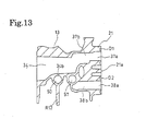
- the first embodiment may be modified by replacing the O-rings used as seal members on the first fitting surface 21a with other seal members shown in Figs. 15 through 17.
- elements and parts common to those of the first embodiment are labeled with common reference numerals.
- an integral O ring S as an integral seal member, which connects, with thin links E, adjacent ones of four O-rings S1 through S4 to fit in the seal retaining grooves D1 through D4 around the housing-side cooling water outlet 37a, housing-side cooling water inlet 38a, housing-side oil outlet 55a and housing-side oil inlet 56a formed through the first fitting surface 21a.
- the first fitting surface 21 includes thin straight grooves W1 through W4 allowing the links E to sit in. If this O-ring is used, assemblage of the O-ring S will be easy, and the productivity will be improved accordingly.
- a disk-shaped flat gasket 80 to be held between the first fitting surface 21a and the fitting surface C1 of the oil cooler C and tightly bound by bolts used to fastening the oil cooler C to the fist mount seat 21.
- This flat gasket 80 has communication bores 81 through 84 corresponding to the opening shapes of the housing-side cooling water outlet 37a, housing-side cooling water inlet 38a, housing-side oil outlet 55a and housing-side oil inlet 56a, and also as a through hole 85 for receiving the bolt B4 (Fig. 3) as well.
- the first fitting surface 21 need not have grooves for receiving seal members. This contributes to a decrease of the machining steps and a reduction of the cost.
- the first fitting surface 21a has formed only two paths, namely, the housing-side cooling water outlet 37a of the first communication path 37 and the housing-side cooling water inlet 38a of the second communication path 38, that are partitioned by a flat plate-like partition wall 21b extending diametrically passing the center of the first fitting surface 21a, thereby to define semicircular openings respectively.
- the oil cooler C has formed, in its fitting surface, only two paths, namely, the cooler-side cooling water inlet 61 and the cooler-side cooling water outlet 62 that are opposed diametrically, and has formed, in its outer side surface opposite from the fitting surface C1, an oil inlet and an oil outlet to be connected to the inflow oil pipe and an outflow oil pipe (both not shown) via pipe joints 86, 87, respectively.
- the filter case 40 may be fabricated as a separate member from the third bracket 13 to be assembled thereto.
- the third bracket 13 may be configured not to assemble any or all of the thermostat case T, tensioner A and alternating-current generator G on. Further, the third bracket 13 may be configured to engage with the other surface of the engine body instead of its front surface.
- the foregoing embodiments have been explained as making communication of the first communication path 37 and the second communication path 38 with the cooler-side cooling water inlet 61 and the cooler-side cooling water outlet 62, respectively, at the first fitting surface 21a; however, they may be modified such that at least one of the housing-side cooling water outlet 37a of the first communication path 37 and the housing-side cooling water inlet 38a of the second communication path 38 opens at another outer surface of the third bracket instead of the first fitting surface 21 thereof, while the cooler-side cooling water inlet 61 and the cooler-side cooling water outlet 62 open at another surface of the oil cooler C instead of its fitting surface C1, and exterior piping makes their communication. Still here, since the exterior piping may be shorter than that of the prior art, the flow path resistance is reduced.
- a mount seat 21 is formed on a bracket 13 as a housing to be affixed to an engine body 1 of a water-cooled engine, and a water-type oil cooler C having a cooling water inlet 61 and a cooling water outlet 62 is affixed to a fitting surface 21a of the mount seat 21.
- the bracket further has formed a pump chamber 32 of a cooling water pump, intake path and release path 34 both communicating with the pump chamber 32, first communication path 37 communicating with the release path 34 within the bracket 13, second communication paths 38a, 38b, 38c communicating with the intake path 33 within the bracket 13.
- the first communication path 37 and the second communication paths 38a, 38b, 38c communicate with a cooling water inlet 61 and cooling water outlet 62 of the oil cooler, respectively, at the fitting surface 21a.
- This configuration contributes to reducing the flow path resistance of the cooling passage for delivery of cooling water to and from the oil cooler C and improving the heat exchange efficiency of the oil cooler C. It also decreases parts and assembling steps, and improves readiness of maintenance.
Abstract
Description
- This invention relates to a housing to be affixed to an engine body of a water-cooled engine, which has attached a water-type oil cooler for cooling lubricant oil. More particularly, the invention relates to configuration of a cooling water path and an oil path formed in the housing.
- Supply and discharge of cooling water to a water-type oil cooler in a lubricant system of a water-cooled engine for cooling oil released from an oil pump was conventionally via an exterior piping. For example, Japanese Patent Laid-Open Publication No. hei 9-13935 discloses a technique with which an oil cooler is attached to a thermostat housing attached to the engine body of an engine; a cooling water outlet is formed in the engine body to communicate with a cooling water pump formed in the engine body and to communicate with the inlet of cooling water of the oil cooler via an exterior piping; and the cooling water outlet of the oil cooler communicates with the cooling water inlet of the thermostat housing via an exterior piping.
- In this prior art, an oil filter is used in the oil cooler. The cooling water inlet of the oil cooler communicates with the cooling water outlet formed in the engine body communicating with the cooling water pump formed in the engine body via the exterior piping, and the cooling water outlet of the oil cooler communicates with the cooling water inlet of the thermostat housing via the exterior piping. Thus, the oil released from the oil pump passes through the oil path in the thermostat housing, and after flowing into the oil cooler through an annular groove formed in a flange for joint with the oil cooler and being cooled therein, it flows into the oil filter. The oil, after filtered by the oil filter, is supplied to an oil gallery inside the engine body through an oil path formed in a stud bolt, which joins the flange, oil cooler and oil filter together, and the oil path in the thermostat housing.
- In the above-introduced prior art, however, since the cooling water released from the cooling water pump in the engine body is supplied to the oil cooler attached to the thermostat housing attached to the engine body via the exterior piping, the cooling water path from the cooling water pump to the oil cooler is long, causing an increase of the flow path resistance and limiting the maximum flow of cooling water that can be delivered, there is the problem that the cooling efficiency of the oil cooler decreases. For nevertheless supplying a large quantity of cooling water to the oil cooler to increase the cooling efficiency, the cooling water pump will inevitably have a large size. In addition, since the oil cooler is supplied with cooling water after passing the engine body from the cooling water outlet, and the cooling water inevitably increases in temperature while it travels through the engine body, there was room for improvement from the viewpoint of the cooling efficiency in the oil cooler. Furthermore, since the use of the exterior piping leads to increasing parts and assembling steps thereof, it is not satisfactory in productivity, and upon maintenance of the oil cooler, the need for disassembling the exterior piping and joint pipes is a bar to a satisfactory work efficiency.
- On the other hand, in the above-discussed prior art, since the oil flowing through the oil path communicating with the oil filter is cooled only on cooling water flowing through the cooling water outlet path communicating with the suction side of the cooling water pump mounted in the engine body, there is room for improvement from the viewpoint of the oil cooling efficiency.
- Furthermore, in the above-discussed prior art, since the cooling water pump provided in the engine body is brought into communication with the oil cooler for the purpose of supplying cooling water to the oil cooler attached o the thermostat case, relatively long exterior piping is required, and reduction of the piping space is insufficient. Taking it into consideration, for the purpose of shortening or removing the exterior piping, if the cooling water pump is also mounted in the thermostat housing like the oil cooler, there arises the problem how the thermostat case, the problem of a compact layout of the oil cooler and cooling water pump newly arises. Moreover, in the prior art under discussion, since the thermostat case and the oil cooler are mounted on flange surfaces different in level, the need of changing the fixed posture of the thermostat housing upon processing of the flange surfaces, for example, increases the time for the processing, and there here again exists room for improvement from the viewpoint of productivity.
- Taking those existing problems into consideration, it is the main object of the invention to improve the efficiency of heat exchange of an water-type oil cooler by reducing the flow path resistance of cooling water paths for supplying and discharging cooling water to the oil cooler in a housing to which the oil cooler is attached.
- A further object of the invention is to provide a housing having a water-type oil cooler mounted therein, which can be assembled with less parts and in less assembling steps, resulting in improving the work efficiency upon maintenance. A still further object of the invention is to improve the efficiency of heat exchange between oil flowing in oil paths communication with the oil filter and water. It is a yet further object of the invention to provide a housing that enables a compact layout of the thermostat case, oil cooler and cooling water pump, facilitates processing of the fitting surface of a mount seat to mount the thermostat case the oil cooler on, and hence ensures a high productivity.
- According to the invention, the main object can be achieved by a housing to be affixed to a water-cooled engine, to which a water-type oil cooler having a cooling water inlet and a cooling water outlet is assembled, characterized in that the housing has formed a pump chamber of a cooling water pump, an intake path communicating with the pump chamber, a release path communicating with the pump chamber, a first communication path communicating with the release path within the housing, and a second communication path communicating with the intake path, the release path being in communication with the cooling water inlet via the first communication path, and the intake path being in communication with the cooling water outlet via the second communication path.
- With this configuration of the housing, the path for cooling water between the cooling water pump and the oil cooler is shortened, and the flow path resistance is also reduced. Further, since the oil cooler is supplied with cooling water released from the pump chamber before flowing out of the housing, the cooling is supplied to the oil cooler while keeping cool after being cooled by the radiator, unlike in the above-discussed prior art in which cooling water is heated while passing through the engine body upon suction to and discharge from the cooling water pump.
- As a result, the following effects are obtained. That is, since the path of cooling water between the cooling water pump and the oil cooler is shortened and the flow path resistance is decreased, a large quantity of cooling water can be supplied to the oil cooler and improves the efficiency of heat exchange of the oil cooler, without the need of increasing the size of the cooling water pump. Further, since all of the pump chamber of the cooling water pump, intake path and release path communicating with the pump chamber, and first and second communication paths in communication with them are formed in the housing to which the oil cooler is attached, the number of parts can be reduced remarkably, and the assembling work efficiency is improved significantly. In addition, since the oil cooler can be supplied with low-temperature cooling water released from the cooling water pump before flowing out of the housing, the cooling efficiency in the oil cooler is improved additionally.
- The oil cooler may be joined to a fitting surface formed on the housing, and the first communication path and the second communication path may communicate with the cooling water inlet and the cooling water outlet, respectively, at the fitting surface (21a).
- With this configuration, connection between the first communication path and the cooling water inlet and connection between the second communication path and the cooling water outlet are established at the fitting surface by joining the oil cooler to the fitting surface of the housing, and cooling water is delivered at the fitting surface. Additionally, upon maintenance, it is sufficient to detach the oil cooler from the housing, instead of additionally removing exterior piping as the prior art did so. Furthermore, it decreases the parts for assemblage of the housing affixed with the oil cooler, hence decreases the cost, and decreases the assembling steps because communication between the housing and the oil cooler is completed by putting the oil cooler into joint with the fitting surface. Then, upon maintenance of the oil cooler, readiness is improved without the need of detaching external piping for delivery of cooling water to or from the oil cooler.
- The release path may be disposed to overlap the fitting surface as viewed from a direction opposed to the fitting surface, and an outlet of the first communication path opening at the fitting surface may be formed to communicate with the release path via a straight path.
- With this arrangement, since the outlet of the first communication path communicates with the release path via a straight passage without curves, the shortest communication can be made between the release path and the outlet of the first communication path. Therefore, the resistance of the passage for cooling water supplied to the oil cooler can be minimized, and more efficient heat exchange of the oil cooler is ensured.
- The oil cooler may be mounted in joint with a fitting surface of a mount seat formed on said housing, the fitting surface may have a cooling water outlet of the housing, a cooling water inlet of the housing, an oil outlet of the housing, and an oil inlet of the housing, such that, at the fitting surface, the cooling water outlet of the housing communicates with a cooling water inlet of the oil cooler, the cooling water inlet communicates with a cooling water outlet of the oil cooler, the oil outlet of the housing communicates with an oil inlet of the oil cooler, and the oil inlet of the housing communicates with an oil outlet of the oil cooler, respectively.
- With this arrangement, delivery of cooling water and oil takes place at the fitting surface. Additionally, upon maintenance, it is sufficient to detach the oil cooler from the housing, instead of additionally removing exterior piping as the prior art did so. Since the configuration for delivery of cooling water and oil at the fitting surface is readily established by putting the oil cooler into joint with the fitting surface of the housing, it contributes to reducing parts of the housing carrying the oil cooler affixed thereto and decreasing the cost. Further, communication of cooling water and oil between the housing and the oil cooler is established by bringing the oil cooler into joint with the fitting surface, assembling steps are reduced. Moreover, upon maintenance of the oil cooler, works therefore can be done easily and quickly by merely detaching the oil cooler from the housing without the need of detaching external piping for delivery of cooling water to or from the oil cooler.
- The cooling water outlet of the housing and the cooling water inlet of the housing are preferably opposed to each other about the center of the fitting surface, and the oil outlet of the housing and the oil inlet of the housing are also preferably opposed to each other about the center of the fitting surface.
- Under the configuration, at the fitting surface, the oil outlet of the housing for oil to flow before being cooled and the oil inlet of the housing for oil after being cooled to flow are relatively distant about the center of the fitting surface, and openings of cooling water paths of the housing, in form of the cooling water outlet and the cooling water inlet, and openings of oil paths of the housing, in form of the oil outlet and the oil inlet, alternately appear in the circumferential direction. As a result, transmission of heat from the oil flowing in the housing-side oil outlet to the oil flowing in the housing-side oil inlet is prevented, and the oil after being cooled by the oil cooler can be maintained at a lowest possible temperature.
- An oil filter may be affixed to the housing, and the oil outlet of the housing can be formed to communicate with an oil path formed in the housing, which in turn communicate with the oil filter, via a straight path formed in the housing.
- With this arrangement, the straight path for making communication between the oil path formed in the housing for communication with the oil filter and the oil inlet of the housing can be made easily, and can decrease the resistance of the passage up to the oil inlet of the cooler which communicates with the housing-side oil outlet at the fitting surface.
- The housing preferably has formed therein oil paths in communication with an oil filter, a cooling water intake path communicating with the pump chamber and a cooling water release path communicating with the pump chamber; and the oil paths, intake path and release path are preferably disposed in locations bringing about heat exchange between oil and cooling water through the body of the housing.
- This configuration ensures the following effects. That is, since the oil flowing in the oil path in communication with the oil filter undergoes heat exchange with the cooling water flowing in the intake path and the release path both communicating with the pump chamber of the cooling water pump, the heat exchange efficiency between oil and cooling water is improved. In addition to this, since the housing defines the pump chamber of the cooling water pump, and the cooling water existing in the pump chamber also contributes to heat exchange between oil and cooling water, the heat exchange efficiency between oil and cooling water in the housing is further enhanced. Besides, temperature of the cooling water in the release path is substantially equal to the temperature of the cooling water in the intake path, the cooling efficiency in the housing is enhanced.
- The oil paths are preferably located between the intake path and the release path. This configuration gives the following effects. That is, since the oil flowing in the oil paths undergoes heat exchange with cooling water in the intake path and the release path at opposite sides of the oil paths, the heat exchange efficiency is further improved. Additionally, since the oil paths are formed by making use of the space between the intake path and the release path, the housing can be designed compactly.
- A water-type oil cooler may be affixed to the housing to introduce oil traveling through the oil filter, ad the oil cooler may have formed therein a path for cooling water supplied from the release path of the cooling water pump and returning back to the intake path. And the oil cooler may be located nearer to the rotating axis of the cooling water pump than the oil filter.
- This configuration ensures the following effects. That is, since the oil cooler introducing the oil after passing the oil filter is located nearer to the cooling water pump, the passage for cooling water for cooling oil can be shortened between the release path and the intake path of the cooling water pump, and the flow path is decreased. As a result, a large quantity of cooling water can be supplied to the oil cooler without increasing the size of the cooling water pump, and the heat exchange efficiency in the oil cooler can be improved.
- The housing may have formed thereon a first mount seat having a first fitting surface for joint with said oil cooler, a second mount seat having a second fitting surface for joint with a thermostat case, and a third mount seat disposed on one side surface of the housing to affix a pump body forming the cooling water pump thereto, and the first mount seat and the second mount seat may be positioned on the other surface of the housing such that the first fitting surface and the second fitting surface are flush.
- This configuration gives the following effects. That is, since the cooling water pump and the oil cooler are disposed on one surface and the other surface of the housing, a compact layout is attained. Additionally, on the other side surface, the oil cooler and the thermostat case are affixed in joint with the first fitting surface and the second fitting surface that are flush, their compact layout is ensured. Further, the fitting surface and the second fitting surface lying common plane can be processed easily, and improves the productivity of the housing.
- The first mount seat and the second mount seat are preferably connected with a reinforcing rib. Thereby, the first mount seat for attachment of the oil cooler and the second mount seat for attachment of the thermostat case are enhanced in rigidity, and the oil cooler, even if relatively heavy, can be affixed firmly.
- The second mount seat preferably has formed a plurality of fastening portions for fastening the thermostat case to the second mount seat, and the reinforcing rib preferably connect one of the fastening portions nearest to the first mount seat with a portion of the first mount seat nearer to the second mount seat.
- This configuration ensures the following effects. That is, the reinforcing rib enhances the rigidity of the fastening portion of the second mount seat for attachment of the thermostat case, and therefore, the thermostat case can be fixed firmly with a large fastening force. Moreover, since the rib is short, it does not invite an increase of weight of the third bracket and hence the weight of the engine.
- More detailed features of the invention, summarized above, will be more apparent from the detailed description given below with reference to the drawings, in which:
- Fig. 1 is a right side-elevational view of an engine having a bracket as a housing to be mounted to the engine, in which a water-type oil cooler is attached;
- Fig. 2 is a front elevational view of the engine shown in Fig. 1;
- Fig. 3 is an exploded perspective view of parts decomposed from the bracket of Fig. 1;
- Fig. 4 is a schematic, perspective phantom view of the bracket, particularly illustrating cooling water paths and oil paths formed in the bracket of Fig. 3;
- Fig. 5 is a front elevational view of the bracket of Fig. 3;
- Fig. 6 is a back elevational view of the bracket of Fig. 3;
- Fig. 7 is a right side-elevational view of the bracket of Fig. 3;
- Fig. 8 is a left side-elevational view of the bracket of Fig. 3;
- Fig. 9 is a cross-sectional view taken along the IX-IX line of Fig. 5;
- Fig. 10 is a cross-sectional view taken along the X-X line of Fig. 5;
- Fig. 11 is a cross-sectional view taken along the XI-XI line of Fig. 6;
- Fig. 12 is a cross-sectional view taken along the XII-XII line of Fig. 6;
- Fig. 13 is a cross-sectional view taken along the XIII-XIII line of Fig. 8;
- Fig. 14 is a fragmentary, exploded, perspective view of an oil cooler with related parts involved, decomposed from the bracket of Fig. 3;
- Fig. 15 is a diagram showing the second embodiment of the invention, in a view corresponding to Fig. 14 of the first embodiment;
- Fig. 16 is a diagram showing the third embodiment of the invention, in a view corresponding to Fig. 14 of the first embodiment; and
- Fig. 17 is a diagram showing the fourth embodiment of the invention, in a view corresponding to Fig. 14 of the first embodiment.
-
- Referring to Figs. 1 through 17, some embodiments of the invention will be explained below.
- Figs. 1 through 14 are used for explaining the first embodiment of the invention in which an engine E is an overhead-camshaft, water-cooled, serial four-cylinder, four-cycle engine to be mounted in a car. In the specification, "front, back, left and right" directions or portions pertain to "front, back, left and right" directions or portions with respect to a car to mount the engine in unless specified otherwise.
- As shown in Figs. 1 and 2, at the upper end of a
cylinder block 1, acylinder head 2 and ahead cover 3 are sequentially stacked and joined together. At the lower end of thecylinder block 1, a lower block 4 is joined, and anoil pan 5 is united to the lower end of the lower block 4. Acrankshaft 6 having a rotating axis on a plane containing the fitting plane between thecylinder block 1 and the lower block 4 is rotatably supported on thecylinder block 1 via a main bearing. - The engine body of the engine E is made up of the
cylinder block 1,cylinder head 2,head cover 3, lower block 4 andoil pan 5, and a lower part of thecylinder block 1, lower lock 4 andoil pan 5 form a crank chamber 17 (see Fig. 9). On the right side (this side of Fig. 1 and the left side in Fig. 2), a timing chain is placed to wrap thecrank shaft 6 and a cam shaft for opening and closing an intake valve and an exhaust valve formed in thecylinder head 2 synchronously with rotation of thecrankshaft 6, and achain cover 7 is fastened to the right end of thecylinder block 1 to define a chain chamber together with the right end for accommodating the timing chain therein. - The
cylinder block 1 has formed four cylinders 8 (see Fig. 9) each having a center axis extending slightly aslant backward from thecrankshaft 6 extending in the right and left direction. A piston (not shown) slidably fits in abore 8a of eachcylinder 8, and reciprocal motion of the piston is converted to rotation of thecrankshaft 6 via a connection rod. - In front (this side surface in Fig. 2) of the
cylinder block 1, an intake unit 9 made up of an intake manifold and others is located, and on the back surface of thecylinder block 1, anexhaust unit 10 made up of an exhaust manifold and others is located. In a right area (left area in Fig. 2), which is one side of the intake unit 9, a plurality of brackets for auxiliary machineries are located to be fastened by bolts to thecylinder head 2,cylinder block 1 and lower block 4. That is, afirst bracket 11 is fastened by bolts to a right portion of the front face of thecylinder head 2; ahydraulic pump 14 for generating hydraulic pressure for hydraulic power steering is attached to thefirst bracket 11; asecond bracket 12 is fastened with bolts to a right, lower portion of the front face of thecylinder block 1 and a right region of the front face of the lower block 4; and an air-conditioning compressor 15 is attached to thesecond bracket 12. Further, in a right, central region of the front face of thecylinder block 1 located between the first andsecond brackets third bracket 13 made of a metal, such as aluminum alloy, as a housing to be attached to the engine body is fastened with bolts, and an alternating-current generator G and apump body 31 of a cooling water pump P (see Fig. 3) are affixed. - Then, as shown in Fig. 1, a driving
pulley 6a is coupled to the right axial end of thecrankshaft 6 extending to the right through thechain cover 7, and anendless belt 16 adjusted in tensile force by a tensioner A is wound on that drivingpulley 6a,hydraulic pump pulley 14a of thehydraulic pump 14, generator pulley G3 of the alternating-current generator G,compressors pulley 15a of thecompressor 15 and cooling water pump pulley P1 of the cooling water pump P. Therefore, these auxiliary machineries are driven to rotate with the driving power of thecrankshaft 6 transmitted from the drivingpulley 6a via theendless belt 16. - Referring to Figs. 3 through 8, in particular Fig. 3, the third bracket 13 includes three support arms 20a, 20b, 20c formed to mount the alternating-current generator G disposed in a vertically central position of the front surface of the third bracket 13; a first mount seat 21 located in a vertically central position of the left side surface of the third bracket 13 to mount a cylindrical water-type oil cooler C on; a second mount seat 22 located below the first mount seat 21 of the left side surface of the third bracket 13; a third mount seat 23 located over an area from a lower portion to a central portion of the right side surface of the third bracket 13 to mount the pump body 31 of the cooling water pump P on; a pump case 30 for the cooling water pump P defining a pump chamber 32 including the third mount seat 23 and opening at the third mount seat 23; and a fourth mount seat 24 located above the third bracket 13 to mount the tensioner A on; a cylindrical filter case 40 for an oil filter F, located in front of the fourth mount seat 24 in an upper part of the third bracket 13 and extending aslant forwardly and upwardly; and a fixture portion 25 located at a vertically central position of the back surface of the third bracket 13 to be joined with a fitting surface 26a of a main mount seat 26 (see Fig. 7) formed on the cylinder block 1.
- Further referring to Figs. 4 through 6, in particular Fig. 6, the
third bracket 13 further includes six fastening portions K1 through K6 in form of boss portions having through holes H1 through H6 extending through thethird bracket 13 in the front-to-back direction so that thethird bracket 13 is fastened to thecylinder block 1 with bolts inserted in the through holes H1 through H6, respectively (among them, a bolt B1 inserted in the through hole H1 is illustrated in Fig. 1). More specifically, on the back surface of thethird bracket 13, there are formed the first and second fastening portions K1, K2 between an upper portion and a central portion of thethird bracket 13, that is, the first fastening portion K1 located in a left part of the third bracket adjacent to thefirst mount seat 21 between thefilter case 40, the fourth mount seat and thefixture portion 25, and the second fastening portion K2 located on a right part of thethird bracket 13; a left and right pair of third and fourth fastening portions K3, K4 on the lowermost part of thethird bracket 13; and a upper and lower pair of fifth and sixth fastening portions K5, K6 on a central part of thethird bracket 13. Among them, the second, fifth and sixth fastening portions K2, K5, K6 are disposed on thefitting surface 25a of thefixture portion 25 for joint with thefitting surface 26a of themain mount seat 26 whereas the first, third and fourth fastening portions K1, K3, K4 are disposed along the circumference of thefixture portion 25. - As shown in Fig. 6, the fist fastening portion K1 is connected to the second, fifth fastening portions K2, K5 and an area near an
oil outlet 56b of a thirdsupply oil path 56, which will be explained later, with reinforcing ribs R1, R2, R3. The third fastening portion K3 is connected to the sixth fastening portion K6 with a reinforcing rib R4, and the fourth fastening portion K4 is connected to an area near anoil inlet 50a of aninflow oil path 50, explained later, communicating with the oil filter F with a reinforcing rib R5. Therefore, the first, third and fourth fastening portions K1, K3, K4 are connected to thefixture portion 25 with reinforcing ribs R1 through R5. Further, the third and fourth fastening portions K3, K4 are connected together with the reinforcing rib R6. - On the other hand, as shown in Fig. 5, on the front surface of the
third bracket 13, the second fastening portion K2 is connected to thepump case 30 with a reinforcing rib R7 extending downward, the third fastening portion K3 and the fourth fastening portion K4 are connected together with a reinforcing rib R8, the fourth fastening portion K4 is also connected to a reinforcing rib R11, which in turn connecting a left and right pair oflower support arms filter case 40 is perpendicularly connected to the reinforcing rib R11, and the sixth fastening portion K6 is connected to the left-sidelower support arm 20a with a reinforcing rib R10. - Furthermore, on a left area of the outer circumferential surface of the
filter case 40, a reinforcingrib R 13 is formed to extend from the top of thefilter case 40 to thefirst mount seat 21 along the center axis of thefilter case 40 to enhance the rigidity of thefilter case 40, and a reinforcing r13 to rib R14 is formed to extend horizontally from the reinforcing rib R13 to the left side surface of anupper support arm 20c, explained later, to enhance the rigidity of theupper support arm 20c. - Since the
filter case 40,first mount seat 21,fourth mount seat 24 andfixture portion 25 are portions having a relatively high rigidity because of the nature of their own, the first and second fastening portions K1, K2 are located between therigid filter case 40,rigid mount seat 24 and therigid fixture portion 25 and the first fastening portion K1 is adjacent to thefirst mount seat 21, thethird bracket 13 can be rigidly fastened to thecylinder block 1 with a large fastening force of bolts at a reduced number of fastening portions. In addition, the reinforcing ribs R1 through R10 connected to the respective fastening portions K1 through K6 enhance the rigidity of the respective fastening portions K1 through K6. - As shown in Figs. 3, 5, 7 and 8, in particular Fig. 3, as support arms integral with the
third bracket 13 to mount the alternating-current generator G on, there are provided a left and right pair oflower support arms third bracket 13 and anupper support arm 20c horizontally extending forward from a lower part of the outer circumferential surface of thefilter case 40. As shown in Figs. 1 and 2, a first mount flange G1 integral with a lower part of the alternating-current generator G is fastened to be held between thelower support arms lower support arms upper support arm 20c with a bolt B3 inserted through a through hole of the second mount flange G2 into engagement with a screwed hole 20c1 of theupper support arm 20c. Thus the alternating-current generator G is mounted to thethird bracket 13. - Under the condition where the alternating-current generator G is assembled to the
third bracket 13, since the alternating-current generator G is positioned using the space defined under the oil filter F projecting aslant forward, forward projection of the alternating-current generator G can be minimized, thereby to compactly position the alternating-current generator G with respect to the engine body. Additionally, the use of the reinforcing rib R14 and theupper support arm 20c formed on therigid filter case 40 contribute to stable support alternating-current generator G. - On the other hand, with reference to Fig. 3, the cooling water pump P includes the
pump case 30,pump body 31 fastened in joint with the thirdfitting surface 23a of thethird mount seat 23 with a bolt, a drive shaft (not shown) supported on thepump body 31 via a bearing and having the cooling water pump pulley P1 fixed at one end thereof, and an impeller (not shown) united to the other end of the drive shaft. - The
pump chamber 32, in which the impeller is disposed, communicates with an intake path of cooling water, in form of a circular hole concentric with the rotation axis L of the drive shaft (common to the rotation axis of the cooling water pump P), which is formed to extend through thethird bracket 13 in the left-to-right direction between a central portion of thepump chamber 32 and thesecond mount seat 22. Thepump case 30 also communicates with arelease path 34 formed to extend tangentially of the rotating direction of the impeller from thepump chamber 32 and having a coolingwater outlet 34a opening at the thirdfitting surface 25a of the fixture portion 25 (see Figs. 6, 7 and 12). The portion of therelease path 34 opening at the thirdfitting surface 23a and thepump chamber 32 are covered with thepump body 31 in a watertight manner. - Mounted on the
second mount seat 22 is a thermostat case T accommodating a thermostat in joint with thefitting surface 22a formed on thesecond mount seat 22 with theintake path 33 opening there. More specifically, as shown in Fig. 8, the secondfitting surface 22a having a substantially rhombic shape has an upper fastening portion K7 and a lower fastening portion K8 having two through holes H7, H8 along the longer diagonal line of the rhombus, and the thermostat case T is fastened with bolts inserted in through holes of the thermostat case T and then into the through holes H7, H8 of the upper and lower fastening portions K7, K8. - The second
fitting surface 22a is disposed on the left surface of thethird bracket 13, which is opposite from the right side surface, viewed from the direction opposed to the thirdfitting surface 23a on the right side surface of thethird bracket 13, i.e. from the direction intersecting approximately at a right angle with the third fitting surface in the first embodiment, together with the firstfitting surface 21a of thefirst mount seat 21 for joint of the oil cooler C as explained later, so as to be flush with the firstfitting surface 21a, that is, to lie on the common plane. Since the cooling water pump P, which is the largest among the thermostat case T, oil cooler C and cooling water pump P, is disposed on the right side surface of thethird bracket 13 and the oil cooler C on the left side surface of thethird bracket 13, a compact layout is achieved. Furthermore, since the oil cooler C and the thermostat case T are attached to thefitting surface 21a and the secondfitting surface 22a that are on the common plane, these both can be assembled compactly. Moreover, since the firstfitting surface 21a and the secondfitting surface 22a are processed to lie on the common plane, thethird bracket 13 need not be changed in the fixed posture upon processing, thereby facilitating the processing and improving the productivity of thethird bracket 13. - Additionally, the
second mount seat 22 is connected to thefirst mount seat 21 with a reinforcing rib R15. Since the reinforcing rib R15 connects the upper fastening portion K7 nearer to thefirst mount seat 21 than the lower fastening portion K8 to the lowest portion of thefirst mount seat 21 nearest to thesecond mount seat 22, length of the reinforcing rib R15 is shortened. Further, a reinforcing rib R16 projecting in a direction intersecting approximately at a right angle with the reinforcing rib R15 connects thefirst mount seat 21 and thesecond mount seat 22. Connection by the reinforcing rib R15 in this manner enhances the rigidity of thefirst mount seat 21 and thesecond mount seat 22, and the reinforcingrib R 16 additionally enhances thesemount seats second mount seat 22, the thermostat case T can be fixed firmly with a large fastening force, and since the reinforcing rib R15 is configured to connect the upper fastening portion K7 nearest to thefirst mount seat 21 to the portion of thefirst mount seat 21 nearest to thesecond mount seat 22, its length is shortened, thereby preventing thethird bracket 13 from being increased in weight due to the existence of the reinforcing rib R16 and hence preventing the engine E from becoming heavy. - The
thermostat cover 35 is water-tightly joined to the thermostat case T. Thethermostat cover 35 has aninflow section 35a (see Figs. 2 and 3) connected to one end of an outlet hose (not shown) having the other end connected to a radiator, not shown. At a portion of the thermostat case T opened and closed by the thermostat, a bypass pipe (not shown) connected to a cooling water jacket of thecylinder head 2 is connected, and a cooling water return pipe 36 (see Fig. 2) from an air-conditioning heater is connected to a connecting portion T1 (see Fig. 3) of the thermostat T. - The thermostat permits cooling water to flow from the bypass pipe to the
intake path 33 while preventing the cooling water from flowing from the outlet hose to theintake path 33 during warming-up where the temperature of the cooling water does not exceed a predetermined value, and after completion of the warming-up where the temperature of the cooling water exceeds the predetermined value, it prevents the flow of the cooling water from the bypass pipe to theintake path 33 while permitting the flow of the cooling water from the outlet hose to theintake path 33. Further, as shown in Fig. 12, a coolingwater inlet 1a communicating with the coolingwater jacket 1b opens to thecylinder block 1 at thefitting surface 26a, so that, once thethird bracket 13 is fastened to themain mount seat 26, the coolingwater inlet 1a communicated with the coolingwater outlet 34a of therelease path 34 at thefitting surface 26a to allow the cooling water released from the cooling water pump P to be supplied to thecylinder block 1. - Therefore, during operation of the engine E, the cooling water pump P sends pressurized cooling water suctioned from the
intake path 33 to therelease path 34 in response to rotation of the impeller disposed in thepump chamber 32. The pressurized cooling water sent to therelease path 34 flows into the coolingwater inlet 1a of thecylinder block 1 communicating with thefitting surface 25a from the coolingwater outlet 34a of therelease path 34, and flows through the coolingwater jacket 1b of thecylinder block 1 while cooling thecylinder block 1, thereafter flows into the cooling water jacket of thecylinder head 2 to cool it. During the warming-up, it flows to the bypass pipe and returns through the thermostat to theintake path 33, and after completion of the warming-up, the cooling water cooled to a low temperature while passing the radiator returns to theintake path 33 through the thermostat. Thus the cooling system circulating the cooling water is established. - Further referring to Figs. 4 through 6, 8, 7, 10 and 13, the
third bracket 13 has afirst communication path 37 having one end communicating with theoutlet path 34 inside thethird bracket 13 and the other end opening at the firstfitting surface 21a having a circular outer circumference of the first mount seat to form a housing-sidecooling water outlet 37a, and asecond communication path 38 having one end communicating with theintake path 33 inside thethird bracket 13 and the other end opening at the firstfitting surface 21a to form a housing-sidecooling water inlet 38a. - The
release path 34 is disposed to overlap the firstfitting surface 21a, when viewed from the direction opposed to the firstfitting surface 21a, i.e. from the left that is a direction intersecting approximately at a right angle with the firstfitting surface 21a in the first embodiment (see Fig. 7), and the housing-sidecooling water outlet 37a of thefirst communication path 37 communicates with therelease path 34 via ahorizontal path section 37b, extending straight without curves, which is formed by drilling to horizontally extend rightward from the housing-sidecooling water outlet 37a toward therelease path 34 and to open to therelease path 34, such that thehorizontal path section 37b makes the shortest passage between the housing-sidecooling water outlet 37a and therelease path 34. On the other hand, as shown in Figs. 4, 5 and 10, thesecond communication path 38 includes ahorizontal path section 38b extending horizontally rightward from the housing-sidecooling water inlet 38a toward therelease path 34 and terminating at the deepest closed end, and avertical path section 38c formed by drilling to extend from the bottom surface of thethird bracket 13 through theintake path 33 toward thehorizontal path section 38b and to open at thehorizontal path section 38b near that closed end. The opening at the bottom end of thevertical path section 38c is closed with aplug 39. - Referring to Figs. 9 and 12, a
cap 43 is brought into threading engagement with thecylindrical filter case 40 such that acylindrical filter element 41 made by alternately folding filter paper and held in aholder 42 attached to thecap 43 is accommodated in a receivingchamber 44 defined by thefilter case 40. Anannular oil path 51 formed along the outer circumference of thefilter element 41 inside the receivingchamber 44 communicates with aninflow oil path 50 formed in thethird bracket 13 and having anoil inlet 50a opening at thefitting surface 25a of thefixture portion 25, and theinflow oil path 50 extends straight aslant downward and backward from the receivingchamber 44 toward thecylinder block 1. Then, theinflow oil path 50 communicates with a release oil path of the oil pump (not shown) provided in theoil pan 5 and driven by the driving power of thecrankshaft 6 via an oil path 1c, formed in thecylinder block 1 and having anoil outlet 1d in communication with theoil inlet 50a at thefitting surface 25a of thefixture portion 25, and an oil path (not shown) formed in the lower block 4. - A
central oil path 52 formed along the inner circumference of thefilter element 41 inside the receivingchamber 44 communicates with anoutflow oil path 53 formed by drilling in an approximately central position of thethird bracket 13 in terms of the left-to-right direction (see Fig. 5) to extend straight aslant downward and backward from the receivingchamber 44 toward thecylinder block 1. The upper part of theoutflow oil path 53 constitutes a firstsupply oil path 54 whereas the lower part of theoutflow oil path 53 constitutes adrain path 57 that can communicate with or disconnect from the firstsupply oil path 54 with the aid of adrain valve 45 provided between them. Thedrain path 57 has anoil outlet 57a opening at thefitting surface 25a of thefixture portion 25, and theoil outlet 57a communicates with anoil path 1e formed in thecylinder block 1 and opening into thecrank chamber 17. - The
drain valve 45 is coupled to theholder 42 via aconnection rod 46, and takes its shutting position for blocking passage between the firstsupply oil path 54 and thedrain path 57 when thecap 43 is attached to thefilter case 40 and keeps the receivingchamber 44 sealed, whereas thedrain valve 45 takes its open position allowing passage between the firstsupply oil path 54 and thedrain path 57 when the sealing of the receivingchamber 44 is released, for example, upon removal of thecap 43 from thefilter case 40. - As a result, when the
cap 43 is removed from thefilter case 40 for, for example, replacement of thefilter element 41, the oil having remained in the receivingchamber 44 flows through thedrain path 57 held in communication with the firstsupply oil path 54 by thedrain valve 45 currently taking its open position, without flowing out from thefilter case 40 extending forward and upward and opening upward, then flows out into thecrank chamber 17 from theoil outlet 57a through theoil path 1e of thecylinder block 1, and returns to theoil pan 5. Therefore, it is prevented that oil spills out from the receivingchamber 44 and soils the floor or ground during, for example, maintenance of the oil filter F. - In the first
supply oil path 54, slightly upstream of thedrain valve 45 at its open position, one end of the secondsupply oil path 55 formed in thethird bracket 13 opens, and the other end thereof constitutes a housing-side oil outlet 55a opening at the firstfitting surface 21a. Referring to Figs. 4 and 5, the secondsupply oil path 55 includes ahorizontal path section 55b extending straight without curves, which is made by drilling to extend horizontally rightward from the housing-side oil outlet 55a toward the firstsupply oil path 54 to intersect substantially at a right angle with the firstsupply oil path 54 and finally open into the firstsupply oil path 54, such that thehorizontal path section 55b makes the shortest passage between the firstsupply oil path 54 and the housing-side oil outlet 55a. - The
third bracket 13 further has formed a thirdsupply oil path 56 for supplying oil cooled by the oil cooler C to the main gallery 1g via anoil inlet 1f opening at thefitting surface 26a of thecylinder block 1 as shown in Fig. 1. One end of the thirdsupply oil path 56 opens at the firstfitting surface 21a to constitute a housing-side oil inlet 56a having a circularly opened configuration, and the other end thereof opens at thefitting surface 25a of thefixture portion 25 to constitute anoil outlet 56b. As shown in Figs. 6 and 11, the thirdsupply oil path 56 includes a firsthorizontal path section 56c extending horizontally rightward from the housing-side oil inlet 56a toward therelease path 34 to terminate at its deepest closed end, and a secondhorizontal path section 56d that opens into the firsthorizontal path section 56c near that closed end, extends horizontally toward thefitting surface 25a substantially at a right angle with the firsthorizontal path section 56c, and defines an oval flow path section to constitute theoil outlet 56b. - As shown in Figs. 4, 9 and 12, the
inflow oil path 50 and theoutflow oil path 53 are disposed between theintake path 33 above them and therelease path 34 below them to enable heat exchange between the oil flowing in theoil paths intake path 33,pump chamber 32 andrelease path 34 by heat conduction through thethird bracket 13 of aluminum alloy. Especially, theinflow oil path 50 is located between therelease path 34 and theintake path 33, leftward adjacent to therelease path 34 such that the extending direction of therelease path 34 and the extending direction of theinflow oil path 50 intersects, as viewed from the direction opposed to the thirdfitting surface 23a (see Fig. 7), and as shown in Figs. 12 and 13, it is disposed adjacent to a portion of therelease path 34 nearer to theintake path 33 via a thinnedpath wall 34b thereof. Further, a reinforcing rib R12 is formed on the outer surface of thepath wall 34b along theinflow oil path 50, and this reinforcing rib R12 also functions as a heat-releasing fin. - Since the
third bracket 13 has formed thepump chamber 32 of the cooling water pump p in addition to theintake path 33 and therelease path 34, thethird bracket 13 is entirely cooled by a relatively large quantity of cooling water within thepump chamber 32, to hence cool the oil in theinflow oil path 50 and the first to thirdsupply oil paths - Now referring to Fig. 8, the first
fitting surface 21a includes the housing-sidecooling water outlet 37a of thefirst communication path 37, housing-sidecooling water inlet 38a of thesecond communication path 38, housing-side oil outlet 55a of the secondsupply oil path 55 and housing-side oil inlet 56a of the thirdsupply oil path 56 such that the housing-sidecooling water outlet 37a and the housing-sidecooling water inlet 38a are substantially in a diametrically opposed relation with respect to the center of the firstfitting surface 20a whereas the housing-side oil outlet 55a and the housing-side oil inlet 56a are substantially in a diametrically opposed relation. Therefore, openings of cooling water paths, in form of the housing-sidecooling water outlet 37a and the housing-sidecooling water inlet 38a, and openings of oil paths, in form of the housing-side oil outlet 55a and the housing-side oil inlet 56a, alternately appear in the circumferential direction of the firstfitting surface 21a. - In the area of the first
fitting surface 21a, the housing-side oil outlet 55a is located at a position nearer to the receivingchamber 44 of the oil filter F while the housing-side oil inlet 56a is disposed at a position nearer to theoil outlet 56b of thefitting surface 25a to make a layout shortening the secondsupply oil path 55 and the thirdsupply oil path 56, respectively, thereby to reduce the flow path resistance. Similarly, the housing-sidecooling water outlet 37a is disposed at a position nearer to the coolingwater outlet 34a of therelease path 34 while the housing-sidecooling water inlet 38a is disposed at a position below the housing-sidecooling water outlet 37a and nearer tointake path 33 to make a layout shortening thefirst communication path 37 and thesecond communication path 38, respectively, thereby to reduce the flow path resistance. - Referring to Fig. 14 in conjunction, in the
first mount seat 21 disposed nearer to the cooling water pump P than the oil filter F in the radial direction of the rotating axis L of the cooling water pump P, a screwedhole 27 is formed at the center of the firstfitting surface 21a to assemble the oil cooler C on. A bolt B4 (see Fig. 3) inserted in a throughhole 60 formed in the oil cooler C is brought into threading engagement with the screwed hole coaxially with the center axis of the cylindrical oil cooler C having the same outer diameter as the outer circumference of the firstfitting surface 21a, thereby to fasten the oil cooler C to thefirst mount seat 21 in joint with the firstfitting surface 21a. - The fitting surface C1 of the oil cooler C, which is substantially the same in diameter as the first fitting surface for joint therewith, includes a cooler-side
cooling water inlet 61 and a cooler-sidecooling water outlet 62 diametrically opposed to each other with respect to the center of the fitting surface C1, and includes a cooler-side oil inlet 63 and a cooler-side oil outlet 64 diametrically opposed to each other. In the heat exchange region for carrying out heat exchange inside the oil cooler C, cooling water is guided to flow from the cooler-sidecooling water inlet 61, thereafter flow both in the axial direction and in two opposite circumferential directions in form of two oppositely flowing streams along a cylindrical path that combines those circumferential streams from opposite directions, such that the cooling water first flows from the cooler-sidecooling water inlet 61, and after heat exchange with oil therein, flows out from the cooler-sidecooling water outlet 62 diametrically opposed to the cooler-sidecooling water inlet 61. In the cylindrical path, a pipe serving as an oil path is immersed. - In correspondence with the cooler-side
cooling water inlet 61, cooler-sidecooling water outlet 62 and cooler-side oil inlet 63, the housing-sidecooling water outlet 37a, housing-sidecooling water inlet 38a and housing-side oil outlet 55a are shaped in ovals to get into alignment with positions o cooler-sidecooling water inlet 61, cooler-sidecooling water outlet 62 and cooler-side oil inlet 63 having circular opening shapes. At these oval housing-sidecooling water outlet 37a and housing-sidecooling water inlet 38a, thehorizontal path sections side oil outlet 64 having a circular opening shape meets the circular housing-side oil inlet 56a. Thus, theseoutlets inlets - Once the oil cooler C is assembled to the
third bracket 13 in joint with the firstfitting surface 21a, the housing-sidecooling wager outlet 37a communicates with the cooler-sidecooling water inlet 61, the housing-sidecooling water inlet 38a with the cooler-sidecooling water outlet 62, the housing-side oil outlet 55a with the cooler-side oil inlet 63, and the housing-side oil inlet 56a with the cooler-side oil outlet 64, respectively, at the firstfitting surface 21a. As a result, as shown by white arrows in figures, the cooling water circulating system of the oil cooler C is established such that part of the pressurized cooling water from the cooling water pump P travels from theoutlet path 34 via thefirst communication path 37, cooler-sidecooling water inlet 61, heat exchanger, cooler-sidecooling water outlet 62 andsecond communication path 38 back to theintake path 33. - Referring to Fig. 6, at the
fitting surface 25a of thefixture portion 25, the coolingwater outlet 34a of therelease path 34 exists near the thirdfitting surface 23a, theoil inlet 50a of theinflow oil path 50 just below the coolingwater outlet 34a, theoil outlet 56b of the thirdsupply oil path 56 near the firstfitting surface 21a, and theoil outlet 57a of thedrain path 57 next to theoil inlet 50a between theoil inlet 50a and theoil outlet 56b, respectively. Seal retaining grooves D5 through D7 are formed to surround theseoutlets inlet 50a to retain O-rings as seal members therein. - On the other hand, the oil drawn from an oil reservoir in the oil pan 5 and released from the oil pump travels, as shown by black arrows in the figures, passing through the oil path of the lower block 4 and the oil path 1c of the cylinder block 1, then entering into the inflow oil path 50 from the oil outlet 1d through the oil inlet 50a, further running from the inflow oil path 50 through the annular oil path 51 of the oil filter F and through the filter element 41 while being filtered thereby, reaching the central oil path 52, running from the central oil path 52 through the first supply oil path 54 and the second supply oil path 55, then reaching the housing-side oil outlet 55a at the first fitting surface 21a, running from the housing-side oil outlet 55a passing through the cooler-side oil inlet 63 while undergoing heat exchange with the cooling water, thereafter reaching the housing-side oil inlet 56a via the cooler-side oil outlet 64, then going from the housing-side oil inlet 56a and reaching the third supply oil path 56 and the oil outlet, then flowing through the oil inlet of the cylinder block 1 into the main gallery, feeding various portions to be lubricated inside the crank chamber 17, such as the bearing portion of the crankshaft 6 and slide-fit portions between pistons and cylinders, for example, and feeding various portions to be lubricated in the valve chamber defined by the cylinder head 2 and the head cover 3, such as slide-fit portions of the drive valve system for driving intake and exhaust valves, further feeding other portions to be lubricated, such as the timing chain, and after lubrication, returning through the return oil path back into the oil pan 5. Thus, the lubricant system circulating the oil is established.
- Referring to Fig. 3, the tensioner A attached to the
fourth mount seat 24 includes a tensionermain body 70 having a cylindricalstationary portion 71 with amount flange 71a and a cylindricalmovable portion 72 that can rotate relative to thestationary portion 71 via a coil spring contained therein, and anidler pulley 73 pivotally supported on a radially outer end portion of themovable portion 72. The coil spring exerts a twisting spring force to theidler pulley 73 such that theidler pulley 73 rotates about a bolt in a direction applying a tensile force to the endless belt 16 (in the counterclockwise direction in Fig. 1). - Referring to Fig. 7 in conjunction, the tensioner A is fastened to the
fourth mount seat 24 with a bolt inserted in a through hole of themount flange 71a and brought into threading engagement with a screwed hole of a periphery fastening portion K9 formed at a portion of thefourth mount seat 24 nearer to thefilter case 40 and with a bolt B6 passing through a central portion of the tensionermain body 70 and brought into threading engagement with a screwed hole in a central fastening portion K10 disposed in a central location of thefourth mount seat 24. The outer circumferential surface of the peripheral fastening portion K9 is connected to thefourth mount seat 24 and thefilter case 40 via three reinforcing ribs R17, R18, R19. - In this manner, the tensioner A is disposed between the
filter case 40 and thecylinder block 1, using a space defined between thefilter case 40, extending upward and forward, and thecylinder block 1. Further, since a part of thefourth mount seat 24 nearer to the oil filter F is integrally connected to thefilter case 40, thereby to enhance the rigidity of thefourth mount seat 24 with the aid of thefilter case 40, the fastening force of the bolts can be increased to firmly fasten the tensioner A. - Operation and effects of the first embodiment having the above-explained configuration will be explained below.
- Since the
third bracket 13 with the oil cooler C assembled thereto has formed therein thepump chamber 32 of the cooling water pump P,intake path 33 andrelease path 34, and additionally has formed therein thefirst communication path 37 communicating with therelease path 34 within thethird bracket 13 and thesecond communication path 38 communicating with theintake path 33, thereby to enable supply and discharge of cooling water to and from the oil cooler C via the first andsecond communication paths third bracket 13 for assembling the oil cooler C to has formed all of thepump chamber 32 of the cooling water pump P,intake path 33 andrelease path 34 communicating with thepump chamber 32,first communication path 37 in communication with therelease path 34 andsecond communication path 38 in communication with theintake path 33, component parts can be decreased remarkably, and the assembling work is made remarkably easier. - Further, the oil cooler C is supplied with cooling water released from the
pump chamber 32 before flowing out of thethird bracket 13, through therelease path 34 and thefirst communication path 37, and the temperature of the cooling water in therelease path 34 is approximately equal to the temperature of the cooling water cooled by the radiator and held at a low temperature in theintake path 33. Therefore, unlike the prior art in which the cooling water is inevitably heated because it flows through the engine body upon introduction to and discharge from the cooling water pump P, the configuration according to the embodiment can supply the cooling water keeping a low temperature to the oil cooler C, thereby to ensure higher cooling efficiency of the oil cooler C. - Because of the configuration of the first
fitting surface 21a for joint with the oil cooler C, including the housing-sidecooling water outlet 37a, housing-sidecooling water inlet 38a, housing-side oil outlet 55a and housing-side oil inlet 56a, such that communication between the housing-sidecooling water outlet 37a and the cooler-sidecooling water inlet 61, between the housing-sidecooling water inlet 38a and the cooler-sidecooling water outlet 62, between the housing-side oil outlet 55a and the cooler-side oil inlet 63, and between the housing-side oil inlet 56a and the cooler-side oil outlet 64 are established by bringing the oil cooler C into joint with the firstfitting surface 21a of thethird bracket 13, thereby to enable delivery of cooling water and oil at the firstfitting surface 21a, the embodiment requires no exterior piping for making communication of the respective inlets and outlets. Accordingly, component parts for assembly of thethird bracket 13 having the oil cooler C attached thereto can be decreased, and the cost can be decreased accordingly. Further, since their communication is completed once the oil cooler C is brought into joint with the firstfitting surface 21a, the assembling steps can be reduced and shortened. Furthermore, upon maintenance of the oil cooler C, it is sufficient to detach the oil cooler C from thethird bracket 13 without the need of detaching such exterior piping for delivering cooling water to or from the oil cooler C as in the prior art. Therefore, maintenance becomes easier. - Since the
release path 34 and the firstfitting surface 21a are located to overlap when viewed from the firstfitting surface 21a, and the housing-sidecooling water outlet 37a of thefirst communication path 37, in communication with the cooler-sidecooling water inlet 61 at the firstfitting surface 21a, communicates with therelease path 34 via the straighthorizontal path section 37b without curves, therelease path 34 and the housing-sidecooling water outlet 37a can be connected in communication by the shortest passage. Therefore, the flow path resistance in the passage of cooling water supplied to the oil cooler C can be minimized, and the heat exchange efficiency of the oil cooler C is improved more. - Because of the relatively distant positioning of the housing-
side oil outlet 55a for oil before being cooled to flow through and the housing-side oil inlet 56a for cooled oil to flow through on thefist fitting surface 21a at opposite sides of the center thereof, and the circumferentially alternate positioning of housing-sidecooling water outlet 37a, opening of the cooling water path as the cooling water inlet, housing-side oil inlet 56a and opening of the oil path as the oil outlet, which results in existence of the housing-sidecooling water outlet 37a and housing-sidecooling water inlet 38a between two cool and hot oil passages, the invention can prevent transmission of heat from the oil flowing in the housing-side oil outlet 55a to the oil flowing in the housing-side oil inlet 56a, and can maintain the oil after being cooled by the oil cooler C at a lowest possible temperature. - Because of the configuration of the heat exchanger in the oil cooler C guiding cooling water over the entire circumference of the heat exchanger by first introducing cooling water from the cooler-side
cooling water inlet 61, then dividing it at the cooler-sidecooling water inlet 61 into axially flowing streams axially flowing through the cylindrical path and opposite circumferential streams flowing in circumferential directions in the cylindrical path to thereafter merge at the cooler-sidecooling water outlet 62 diametrically opposite from the cooler-sidecooling water inlet 61, the embodiment ensures sufficient heat exchange between the cooling water and the oil introduced into the oil cooler C, and ensures high heat exchange efficiency. - Because the
horizontal path section 55b making communication between the firstsupply oil path 54 in thethird bracket 13 and the housing-side oil outlet 55a has a straight configuration without curves, thehorizontal path section 55b can be readily made by drilling, and can minimize the flow path resistance of the passage up to the cooler-side oil inlet 63 in communication with the housing-side oil outlet 55a at the firstfitting surface 21a. - Because of the positioning of the
inflow oil path 50 between theintake path 33 and therelease path 34 to enable heat exchange, in particular via thethird bracket 13 of aluminum alloy, between oil flowing in theinflow oil path 50 and the cooling water flowing in theintake path 33,pump chamber 32 andrelease path 34, the embodiment ensures heat exchange of the oil flowing in theinflow oil path 50 not only with the cooling water flowing in theintake path 33 in communication with thepump chamber 32 of the cooling water pump P but also with the cooling water flowing in therelease path 34, so as to use heat exchange from opposite sides of theinflow oil path 50, thereby increases the area where heat exchange with cooling water occurs, and increases the heat exchange quantity. Further, since thethird bracket 13 includes therein the built-inpump chamber 32 for the cooling water pump P in addition to theintake path 33 and therelease path 34, the cooling water in thepump chamber 32 can be also used for heat exchange with the oil. - As a result, during warming-up of the engine E, since the cooling water passing the bypass pipe circulates, the oil traveling in the
inflow oil path 50 and the first to thirdsupply oil paths third bracket 13 is warmed by the cooling water traveling through theintake path 33,release path 34 and pumpchamber 32 where a relatively large quantity of cooling water exists, and further warmed in the coil cooler C as well. Especially, the oil in theinflow oil path 50 is warmed more because it undergoes efficient heat exchange with the cooling water through the thinnedpassage wall 34b of therelease path 34. This configuration of promoting the rise of temperature of the oil supplied to the main gallery of thecylinder block 1 contributes to reducing the output loss that will occur otherwise because of a high viscosity of oil at a low temperature, and thereby improves the specific fuel consumption. - Once the engine E is warmed up, cooling water cooled by the radiator to a low temperature begins to circulate. Therefore, the oil traveling in the
inflow oil path 50 and the first to thirdsupply oil paths third bracket 13 is warmed by the cooling water traveling through theintake path 33,release path 34 and pumpchamber 32 where a relatively large quantity of cooling water exists, and further warmed in the coil cooler C as well. At that time, unlike the prior art inevitably heating the cooling water because it travels in the engine body upon introduction to and discharge from the cooling water pump P, the embodiment can maintain the cooling water in therelease path 34 at a temperature substantially equal to a low temperature of the cooling water cooled by the radiator and introduced into theintake path 33. Additionally, the thinnedwall 34b of therelease path 34 contributes to more efficient heat exchange of the oil in theinflow oil path 50 with the cooling water. In this manner, the oil supplied to the main gallery 1g is cooled well, and problems caused by oil decreased in viscosity due to heat, such as insufficient lubrication, can be prevented. Thus the configuration of the embodiment can efficiently cool the oil basically in the third bracket before flowing into the oil cooler C and thereafter in the oil cooler C as well, and therefore allows the oil cooler C to be designed compactly. - The
inflow oil path 50 and theoutflow oil path 53 are formed by making use of a space between theintake path 33 and therelease path 34, thethird bracket 13 can be made compact. - The oil after passing the oil filter F flows into the oil cooler C using the cooling water supplied from the
release path 34 of the cooling water pump P and returning to theintake path 33 and cooled there. In this configuration, the oil cooler C, affixed to thefirst mount seat 21 disposed nearer to the cooling water pump P than the oil filter F in the radial direction with respect to the rotating axis L of the cooling water pump P, results in lying nearer to the cooling water pump P than the oil filter F. Therefore, the passage of cooling water for cooling the oil between therelease path 34,intake path 33 and the oil cooler C can be shortened. This results in reducing the flow path resistance, enabling a large quantity of cooling water to be supplied to the oil cooler C without increasing the size of the cooling water pump C, and improving the heat exchange efficiency in the oil cooler C. - Next explained are some embodiments partly modified from the first embodiment already explained, extracting the modified features.
- The first embodiment may be modified by replacing the O-rings used as seal members on the first
fitting surface 21a with other seal members shown in Figs. 15 through 17. In these drawings, elements and parts common to those of the first embodiment are labeled with common reference numerals. - In the second embodiment shown in Fig. 15, here is used an integral O ring S as an integral seal member, which connects, with thin links E, adjacent ones of four O-rings S1 through S4 to fit in the seal retaining grooves D1 through D4 around the housing-side
cooling water outlet 37a, housing-sidecooling water inlet 38a, housing-side oil outlet 55a and housing-side oil inlet 56a formed through the firstfitting surface 21a. Thus, the firstfitting surface 21 includes thin straight grooves W1 through W4 allowing the links E to sit in. If this O-ring is used, assemblage of the O-ring S will be easy, and the productivity will be improved accordingly. - In the third embodiment shown in Fig. 16, here is used a disk-shaped
flat gasket 80 to be held between the firstfitting surface 21a and the fitting surface C1 of the oil cooler C and tightly bound by bolts used to fastening the oil cooler C to the fist mountseat 21. Thisflat gasket 80 has communication bores 81 through 84 corresponding to the opening shapes of the housing-sidecooling water outlet 37a, housing-sidecooling water inlet 38a, housing-side oil outlet 55a and housing-side oil inlet 56a, and also as a throughhole 85 for receiving the bolt B4 (Fig. 3) as well. With this configuration, the firstfitting surface 21 need not have grooves for receiving seal members. This contributes to a decrease of the machining steps and a reduction of the cost. - In the fourth embodiment shown in Fig. 17, here is used a single circular O-ring S5 for fitting in an annular seal retaining groove D8 formed along the circumference of the first
fitting surface 21a in correspondence with the shapes of the circular firstfitting surface 21a and the fitting surface C1 of the oil cooler C. In this case, the firstfitting surface 21a has formed only two paths, namely, the housing-sidecooling water outlet 37a of thefirst communication path 37 and the housing-sidecooling water inlet 38a of thesecond communication path 38, that are partitioned by a flat plate-like partition wall 21b extending diametrically passing the center of the firstfitting surface 21a, thereby to define semicircular openings respectively. - On the other hand, the oil cooler C has formed, in its fitting surface, only two paths, namely, the cooler-side
cooling water inlet 61 and the cooler-sidecooling water outlet 62 that are opposed diametrically, and has formed, in its outer side surface opposite from the fitting surface C1, an oil inlet and an oil outlet to be connected to the inflow oil pipe and an outflow oil pipe (both not shown) via pipe joints 86, 87, respectively. - With this configuration, since the housing-side
cooling water outlet 37a and the cooler-sidecooling water inlet 61 communicate, and the housing-sidecooling water inlet 38a and the cooler-sidecooling water outlet 62 communicate, respectively, at the firstfitting surface 21a, the same effects are ensured regarding cooling water passages for delivery of cooling water to and from the oil cooler C. - Although the foregoing embodiments use the third bracket having the built-in
filter case 40 for the oil filter F, thefilter case 40 may be fabricated as a separate member from thethird bracket 13 to be assembled thereto. Thethird bracket 13 may be configured not to assemble any or all of the thermostat case T, tensioner A and alternating-current generator G on. Further, thethird bracket 13 may be configured to engage with the other surface of the engine body instead of its front surface. - The foregoing embodiments have been explained as making communication of the
first communication path 37 and thesecond communication path 38 with the cooler-sidecooling water inlet 61 and the cooler-sidecooling water outlet 62, respectively, at the firstfitting surface 21a; however, they may be modified such that at least one of the housing-sidecooling water outlet 37a of thefirst communication path 37 and the housing-sidecooling water inlet 38a of thesecond communication path 38 opens at another outer surface of the third bracket instead of the firstfitting surface 21 thereof, while the cooler-sidecooling water inlet 61 and the cooler-sidecooling water outlet 62 open at another surface of the oil cooler C instead of its fitting surface C1, and exterior piping makes their communication. Still here, since the exterior piping may be shorter than that of the prior art, the flow path resistance is reduced. - A
mount seat 21 is formed on abracket 13 as a housing to be affixed to anengine body 1 of a water-cooled engine, and a water-type oil cooler C having a coolingwater inlet 61 and a coolingwater outlet 62 is affixed to afitting surface 21a of themount seat 21. The bracket further has formed apump chamber 32 of a cooling water pump, intake path and releasepath 34 both communicating with thepump chamber 32,first communication path 37 communicating with therelease path 34 within thebracket 13,second communication paths intake path 33 within thebracket 13. Thefirst communication path 37 and thesecond communication paths water inlet 61 and coolingwater outlet 62 of the oil cooler, respectively, at thefitting surface 21a. This configuration contributes to reducing the flow path resistance of the cooling passage for delivery of cooling water to and from the oil cooler C and improving the heat exchange efficiency of the oil cooler C. It also decreases parts and assembling steps, and improves readiness of maintenance.
Claims (12)
- A housing to be affixed to a water-cooled engine, to which a water-type oil cooler (C) having a cooling water inlet (61) and a cooling water outlet (62) is assembled, characterized in:said housing (13) having formed a pump chamber (32) of a cooling water pump (P), an intake path (33) communicating with said pump chamber (32), a release path (34) communicating with said pump chamber (32), a first communication path (37) communicating with said release path (34) within said housing (13), and a second communication path (38) communicating with said intake path (33), said release path (34) being in communication with said cooling water inlet (61) via said first communication path (37), and said intake path (33) being in communication with said cooling water outlet (62) via said second communication path (38).
- A housing according to claim 1 wherein said oil cooler (C) is joined to a fitting surface (21a) formed on said housing (13), and said first communication path (37) and said second communication path (38) communicate with said cooling water inlet (61) and said cooling water outlet (62), respectively, at said fitting surface (21a).
- A housing according to claim 2 wherein said release path (34) is disposed to overlap said fitting surface (21a) as viewed from a direction opposed to said fitting surface (21a), and an outlet (37a) of said first communication path (37) opening at said fitting surface (21a) communicates with said release path (34) via a straight path (37b).
- A housing according to claim 1 wherein said oil cooler (C) is mounted in joint with a fitting surface (21a) of a mount seat (21) formed on said housing (13), said fitting surface (21a) having a cooling water outlet (37a) of the housing, a cooling water inlet (38a) of the housing, an oil outlet (55a) of the housing, and an oil inlet (56a) of the housing, such that, at said fitting surface (21a), said cooling water outlet (37a) of the housing communicates with a cooling water inlet (61) of the oil cooler, said cooling water inlet (38a) communicates with a cooling water outlet (62) of the oil cooler, said oil outlet (55a) of the housing communicates with an oil inlet (63) of the oil cooler, and said oil inlet (56a) of the housing communicates with an oil outlet (64) of the oil cooler, respectively.
- A housing according to claim 4 wherein, about the center of said fitting surface (21a), said cooling water outlet (37a) of the housing and said cooling water inlet (38a) of the housing are opposed to each other whereas said oil outlet (55a) of the housing and said oil inlet (56a) of the housing are opposed to each other.
- A housing according to clam 4 wherein an oil filter (F) is affixed to said housing (13), and said oil outlet (55a) of the housing communicates with an oil path (50) formed in said housing to communicate with said oil filter (F), via a straight path (55b) formed in said housing.
- A housing according to claim 1 wherein said housing has formed therein oil paths (50, 53) in communication with an oil filter (F), a cooling water intake path (33) communicating with said pump chamber (32) and a cooling water release path (34) communicating with said pump chamber (32), and wherein said oil paths (50, 53), said intake path (33) and said release path (34) are disposed in locations bringing about heat exchange between oil and cooling water through the body of said housing.
- A housing according to claim 7 wherein said oil paths (50, 53) are located between said intake path (33) and said release path (34).
- A housing according to claim 8 wherein a water-type oil cooler (C) is affixed to said housing (13) to introduce oil traveling through said oil filter (F), said oil cooler (C) having formed therein a path for cooling water supplied from said release path (34) of said cooling water pump (P) and returning back to said intake path (33), and said oil cooler (C) being located nearer to the rotating axis of said cooling water pump (P) than said oil filter (F).
- A housing according to claim 1 wherein said housing (13) has formed thereon a first mount seat (21) having a first fitting surface (21a) for joint with said oil cooler (C), a second mount seat (22) having a second fitting surface (22a) for joint with a thermostat case (T), and a third mount seat (23) disposed on one side surface of said housing (13) to affix a pump body (31) forming said cooling water pump (P) thereto, and wherein said first mount seat (21) and said second mount seat (22) are positioned on the other surface of said housing (13) such that said first fitting surface (21a) and said second fitting surface (22a) are flush.
- A housing according to claim 10 wherein said first mount seat (21) and said second mount seat (22) are connected with a reinforcing rib (R15).
- A housing according to claim 11 wherein said second mount seat (22) has formed a plurality of fastening portions (K7, K8) for fastening said thermostat case (T) to said second mount seat (22), and said reinforcing rib (R15) connects one (K7) of said fastening portions nearest to said first mount seat (21) with a portion of said first mount seat (21) nearer to said second mount seat (22).
Applications Claiming Priority (4)
| Application Number | Priority Date | Filing Date | Title |
|---|---|---|---|
| JP2000367627 | 2000-12-01 | ||
| JP2000367627A JP3786253B2 (en) | 2000-12-01 | 2000-12-01 | Auto tensioner mounting structure |
| JP2000368758 | 2000-12-04 | ||
| JP2000368758A JP3748205B2 (en) | 2000-12-04 | 2000-12-04 | housing |
Publications (2)
| Publication Number | Publication Date |
|---|---|
| EP1211391A1 true EP1211391A1 (en) | 2002-06-05 |
| EP1211391B1 EP1211391B1 (en) | 2007-04-04 |
Family
ID=26605116
Family Applications (1)
| Application Number | Title | Priority Date | Filing Date |
|---|---|---|---|
| EP01128637A Expired - Lifetime EP1211391B1 (en) | 2000-12-01 | 2001-11-30 | Housing to be affixed to an engine |
Country Status (2)
| Country | Link |
|---|---|
| EP (1) | EP1211391B1 (en) |
| DE (1) | DE60127643T2 (en) |
Cited By (7)
| Publication number | Priority date | Publication date | Assignee | Title |
|---|---|---|---|---|
| EP1443187A1 (en) * | 2003-01-28 | 2004-08-04 | DEUTZ Aktiengesellschaft | Cooling water pump module |
| EP1489279A1 (en) * | 2003-06-18 | 2004-12-22 | Nissan Motor Company, Limited | Water pump for internal combustion engine |
| DE202004011114U1 (en) * | 2004-07-14 | 2005-11-24 | Hengst Gmbh & Co.Kg | Oil module with water pump and heat exchanger |
| DE202004018136U1 (en) * | 2004-07-14 | 2005-11-24 | Daimlerchrysler Ag | Oil-coolant module |
| FR2871516A1 (en) * | 2004-06-15 | 2005-12-16 | Renault Sas | COOLING SYSTEM FOR MOTOR VEHICLE WITH WATER CIRCUIT AND OIL CIRCUIT |
| WO2007128304A2 (en) * | 2006-05-10 | 2007-11-15 | Hengst Gmbh & Co. Kg | Oil module comprising an integrated cooling water channel |
| EP1953377A3 (en) * | 2007-01-30 | 2010-07-28 | DEUTZ Aktiengesellschaft | Water pump carrier for fitting to a combustion engine |
Families Citing this family (3)
| Publication number | Priority date | Publication date | Assignee | Title |
|---|---|---|---|---|
| DE102007051717A1 (en) * | 2007-10-30 | 2009-05-07 | GM Global Technology Operations, Inc., Detroit | unit carrier |
| US8601997B2 (en) * | 2010-05-17 | 2013-12-10 | GM Global Technology Operations LLC | Water pump with integrated oil cooler |
| US9458967B2 (en) | 2013-12-31 | 2016-10-04 | Ingersoll-Rand Company | Integrated lubrication cooling system |
Citations (4)
| Publication number | Priority date | Publication date | Assignee | Title |
|---|---|---|---|---|
| US4370957A (en) * | 1980-01-24 | 1983-02-01 | Hans List | Assembly of auxiliary equipment for a water-cooled internal combustion engine |
| US5647306A (en) * | 1994-10-14 | 1997-07-15 | Perkins Limited | Assembly of auxiliary apparatus for an internal combustion engine |
| US5704329A (en) * | 1996-03-28 | 1998-01-06 | Mercedes-Benz Ag | Engine front cover |
| EP1063397A2 (en) * | 1999-06-23 | 2000-12-27 | Concentric Pumps Limited | Pump housing for internal combustion engine |
Family Cites Families (2)
| Publication number | Priority date | Publication date | Assignee | Title |
|---|---|---|---|---|
| GB678902A (en) * | 1948-10-01 | 1952-09-10 | Daimler Benz Ag | New or improved cooler arrangement in internal combustion engines |
| WO1999059696A1 (en) * | 1998-05-21 | 1999-11-25 | Purolator Products Company | Device in an appliance for the treatment of oil for lubrication of an engine |
-
2001
- 2001-11-30 EP EP01128637A patent/EP1211391B1/en not_active Expired - Lifetime
- 2001-11-30 DE DE2001627643 patent/DE60127643T2/en not_active Expired - Fee Related
Patent Citations (4)
| Publication number | Priority date | Publication date | Assignee | Title |
|---|---|---|---|---|
| US4370957A (en) * | 1980-01-24 | 1983-02-01 | Hans List | Assembly of auxiliary equipment for a water-cooled internal combustion engine |
| US5647306A (en) * | 1994-10-14 | 1997-07-15 | Perkins Limited | Assembly of auxiliary apparatus for an internal combustion engine |
| US5704329A (en) * | 1996-03-28 | 1998-01-06 | Mercedes-Benz Ag | Engine front cover |
| EP1063397A2 (en) * | 1999-06-23 | 2000-12-27 | Concentric Pumps Limited | Pump housing for internal combustion engine |
Cited By (14)
| Publication number | Priority date | Publication date | Assignee | Title |
|---|---|---|---|---|
| EP1443187A1 (en) * | 2003-01-28 | 2004-08-04 | DEUTZ Aktiengesellschaft | Cooling water pump module |
| US7004118B2 (en) | 2003-06-18 | 2006-02-28 | Nissan Motor Co., Ltd. | Water pump for internal combustion engine |
| EP1489279A1 (en) * | 2003-06-18 | 2004-12-22 | Nissan Motor Company, Limited | Water pump for internal combustion engine |
| CN100434662C (en) * | 2003-06-18 | 2008-11-19 | 日产自动车株式会社 | Water pump for internal combustion engine |
| FR2871516A1 (en) * | 2004-06-15 | 2005-12-16 | Renault Sas | COOLING SYSTEM FOR MOTOR VEHICLE WITH WATER CIRCUIT AND OIL CIRCUIT |
| WO2006003336A1 (en) * | 2004-06-15 | 2006-01-12 | Renault S.A.S | Cooling system for a motor vehicle with water circuit and oil circuit |
| DE202004018136U1 (en) * | 2004-07-14 | 2005-11-24 | Daimlerchrysler Ag | Oil-coolant module |
| DE202004011114U1 (en) * | 2004-07-14 | 2005-11-24 | Hengst Gmbh & Co.Kg | Oil module with water pump and heat exchanger |
| US8783216B2 (en) | 2004-07-14 | 2014-07-22 | Hengst Gmbh & Co. Kg | Oil/coolant module with coolant treatment system |
| WO2007128304A2 (en) * | 2006-05-10 | 2007-11-15 | Hengst Gmbh & Co. Kg | Oil module comprising an integrated cooling water channel |
| WO2007128304A3 (en) * | 2006-05-10 | 2008-12-04 | Hengst Gmbh & Co Kg | Oil module comprising an integrated cooling water channel |
| CN101473112B (en) * | 2006-05-10 | 2011-06-15 | 亨格斯特有限及两合公司 | Oil module comprising an integrated cooling water channel |
| US8635984B2 (en) | 2006-05-10 | 2014-01-28 | Hengst Gmbh & Co. Kg | Oil module comprising an integrated cooling water channel |
| EP1953377A3 (en) * | 2007-01-30 | 2010-07-28 | DEUTZ Aktiengesellschaft | Water pump carrier for fitting to a combustion engine |
Also Published As
| Publication number | Publication date |
|---|---|
| DE60127643D1 (en) | 2007-05-16 |
| DE60127643T2 (en) | 2007-07-19 |
| EP1211391B1 (en) | 2007-04-04 |
Similar Documents
| Publication | Publication Date | Title |
|---|---|---|
| EP1211390B1 (en) | Unit housing for supporting auxiliary machineries of an engine | |
| US7347169B2 (en) | Cooling oil delivery structure for a vehicular generator, and engine including same | |
| US7448355B2 (en) | Integrated power unit including split crankcase with reinforced fastening arrangement, and vehicle including same | |
| AU2013205955B2 (en) | Water cooled internal combustion engine for vehicle | |
| US20070199524A1 (en) | Cooling system for an internal combustion engine, and engine incorporating same | |
| EP1211391B1 (en) | Housing to be affixed to an engine | |
| JP4757060B2 (en) | Auxiliary structure of internal combustion engine for motorcycle | |
| US6412451B2 (en) | Cooling water circulating structure in internal combustion engine | |
| US11143085B2 (en) | Cooling structure for internal combustion engine | |
| JP4425885B2 (en) | housing | |
| JP3852723B2 (en) | Vertical internal combustion engine | |
| JP3802752B2 (en) | housing | |
| JP3824134B2 (en) | housing | |
| JP3748205B2 (en) | housing | |
| US7367293B2 (en) | Four-stroke engine | |
| JP4662875B2 (en) | Oil supply path structure for cam chain tensioner of internal combustion engine | |
| JP3835668B2 (en) | housing | |
| CA2503227C (en) | Snowmobile | |
| JP3883381B2 (en) | Auxiliary unit block for internal combustion engine | |
| JP4246016B2 (en) | Engine cooling structure | |
| JP2007262928A (en) | Cooling water passage structure of internal combustion engine | |
| JP4990249B2 (en) | 4-cycle air-oil cooled engine | |
| JP2704659B2 (en) | Engine unit for vehicle | |
| JP2010071129A (en) | Structure of engine cooling oil passage | |
| JP2006275026A (en) | Water-cooled internal combustion engine |
Legal Events
| Date | Code | Title | Description |
|---|---|---|---|
| PUAI | Public reference made under article 153(3) epc to a published international application that has entered the european phase |
Free format text: ORIGINAL CODE: 0009012 |
|
| AK | Designated contracting states |
Kind code of ref document: A1 Designated state(s): AT BE CH CY DE DK ES FI FR GB GR IE IT LI LU MC NL PT SE TR |
|
| AX | Request for extension of the european patent |
Free format text: AL;LT;LV;MK;RO;SI |
|
| 17P | Request for examination filed |
Effective date: 20020703 |
|
| AKX | Designation fees paid |
Designated state(s): DE GB |
|
| 17Q | First examination report despatched |
Effective date: 20050504 |
|
| 17Q | First examination report despatched |
Effective date: 20050504 |
|
| GRAP | Despatch of communication of intention to grant a patent |
Free format text: ORIGINAL CODE: EPIDOSNIGR1 |
|
| GRAS | Grant fee paid |
Free format text: ORIGINAL CODE: EPIDOSNIGR3 |
|
| GRAA | (expected) grant |
Free format text: ORIGINAL CODE: 0009210 |
|
| AK | Designated contracting states |
Kind code of ref document: B1 Designated state(s): DE GB |
|
| REG | Reference to a national code |
Ref country code: GB Ref legal event code: FG4D |
|
| REF | Corresponds to: |
Ref document number: 60127643 Country of ref document: DE Date of ref document: 20070516 Kind code of ref document: P |
|
| PLBE | No opposition filed within time limit |
Free format text: ORIGINAL CODE: 0009261 |
|
| STAA | Information on the status of an ep patent application or granted ep patent |
Free format text: STATUS: NO OPPOSITION FILED WITHIN TIME LIMIT |
|
| 26N | No opposition filed |
Effective date: 20080107 |
|
| PGFP | Annual fee paid to national office [announced via postgrant information from national office to epo] |
Ref country code: DE Payment date: 20081127 Year of fee payment: 8 |
|
| PG25 | Lapsed in a contracting state [announced via postgrant information from national office to epo] |
Ref country code: DE Free format text: LAPSE BECAUSE OF NON-PAYMENT OF DUE FEES Effective date: 20100601 |
|
| PGFP | Annual fee paid to national office [announced via postgrant information from national office to epo] |
Ref country code: GB Payment date: 20101124 Year of fee payment: 10 |
|
| GBPC | Gb: european patent ceased through non-payment of renewal fee |
Effective date: 20121130 |
|
| PG25 | Lapsed in a contracting state [announced via postgrant information from national office to epo] |
Ref country code: GB Free format text: LAPSE BECAUSE OF NON-PAYMENT OF DUE FEES Effective date: 20121130 |