EP1063397A2 - Pump housing for internal combustion engine - Google Patents
Pump housing for internal combustion engine Download PDFInfo
- Publication number
- EP1063397A2 EP1063397A2 EP00305246A EP00305246A EP1063397A2 EP 1063397 A2 EP1063397 A2 EP 1063397A2 EP 00305246 A EP00305246 A EP 00305246A EP 00305246 A EP00305246 A EP 00305246A EP 1063397 A2 EP1063397 A2 EP 1063397A2
- Authority
- EP
- European Patent Office
- Prior art keywords
- pump
- coolant
- lubricant
- pump housing
- housing
- Prior art date
- Legal status (The legal status is an assumption and is not a legal conclusion. Google has not performed a legal analysis and makes no representation as to the accuracy of the status listed.)
- Withdrawn
Links
Images


Classifications
-
- F—MECHANICAL ENGINEERING; LIGHTING; HEATING; WEAPONS; BLASTING
- F04—POSITIVE - DISPLACEMENT MACHINES FOR LIQUIDS; PUMPS FOR LIQUIDS OR ELASTIC FLUIDS
- F04D—NON-POSITIVE-DISPLACEMENT PUMPS
- F04D29/00—Details, component parts, or accessories
-
- F—MECHANICAL ENGINEERING; LIGHTING; HEATING; WEAPONS; BLASTING
- F01—MACHINES OR ENGINES IN GENERAL; ENGINE PLANTS IN GENERAL; STEAM ENGINES
- F01P—COOLING OF MACHINES OR ENGINES IN GENERAL; COOLING OF INTERNAL-COMBUSTION ENGINES
- F01P5/00—Pumping cooling-air or liquid coolants
- F01P5/10—Pumping liquid coolant; Arrangements of coolant pumps
-
- F—MECHANICAL ENGINEERING; LIGHTING; HEATING; WEAPONS; BLASTING
- F01—MACHINES OR ENGINES IN GENERAL; ENGINE PLANTS IN GENERAL; STEAM ENGINES
- F01M—LUBRICATING OF MACHINES OR ENGINES IN GENERAL; LUBRICATING INTERNAL COMBUSTION ENGINES; CRANKCASE VENTILATING
- F01M1/00—Pressure lubrication
- F01M1/02—Pressure lubrication using lubricating pumps
-
- F—MECHANICAL ENGINEERING; LIGHTING; HEATING; WEAPONS; BLASTING
- F01—MACHINES OR ENGINES IN GENERAL; ENGINE PLANTS IN GENERAL; STEAM ENGINES
- F01M—LUBRICATING OF MACHINES OR ENGINES IN GENERAL; LUBRICATING INTERNAL COMBUSTION ENGINES; CRANKCASE VENTILATING
- F01M5/00—Heating, cooling, or controlling temperature of lubricant; Lubrication means facilitating engine starting
- F01M5/002—Cooling
-
- F—MECHANICAL ENGINEERING; LIGHTING; HEATING; WEAPONS; BLASTING
- F01—MACHINES OR ENGINES IN GENERAL; ENGINE PLANTS IN GENERAL; STEAM ENGINES
- F01M—LUBRICATING OF MACHINES OR ENGINES IN GENERAL; LUBRICATING INTERNAL COMBUSTION ENGINES; CRANKCASE VENTILATING
- F01M11/00—Component parts, details or accessories, not provided for in, or of interest apart from, groups F01M1/00 - F01M9/00
- F01M11/03—Mounting or connecting of lubricant purifying means relative to the machine or engine; Details of lubricant purifying means
-
- F—MECHANICAL ENGINEERING; LIGHTING; HEATING; WEAPONS; BLASTING
- F01—MACHINES OR ENGINES IN GENERAL; ENGINE PLANTS IN GENERAL; STEAM ENGINES
- F01M—LUBRICATING OF MACHINES OR ENGINES IN GENERAL; LUBRICATING INTERNAL COMBUSTION ENGINES; CRANKCASE VENTILATING
- F01M1/00—Pressure lubrication
- F01M1/10—Lubricating systems characterised by the provision therein of lubricant venting or purifying means, e.g. of filters
- F01M2001/1007—Lubricating systems characterised by the provision therein of lubricant venting or purifying means, e.g. of filters characterised by the purification means combined with other functions
- F01M2001/1014—Lubricating systems characterised by the provision therein of lubricant venting or purifying means, e.g. of filters characterised by the purification means combined with other functions comprising supply of additives
-
- F—MECHANICAL ENGINEERING; LIGHTING; HEATING; WEAPONS; BLASTING
- F01—MACHINES OR ENGINES IN GENERAL; ENGINE PLANTS IN GENERAL; STEAM ENGINES
- F01M—LUBRICATING OF MACHINES OR ENGINES IN GENERAL; LUBRICATING INTERNAL COMBUSTION ENGINES; CRANKCASE VENTILATING
- F01M1/00—Pressure lubrication
- F01M1/10—Lubricating systems characterised by the provision therein of lubricant venting or purifying means, e.g. of filters
- F01M2001/105—Lubricating systems characterised by the provision therein of lubricant venting or purifying means, e.g. of filters characterised by the layout of the purification arrangements
- F01M2001/1092—Lubricating systems characterised by the provision therein of lubricant venting or purifying means, e.g. of filters characterised by the layout of the purification arrangements comprising valves bypassing the filter
-
- F—MECHANICAL ENGINEERING; LIGHTING; HEATING; WEAPONS; BLASTING
- F01—MACHINES OR ENGINES IN GENERAL; ENGINE PLANTS IN GENERAL; STEAM ENGINES
- F01M—LUBRICATING OF MACHINES OR ENGINES IN GENERAL; LUBRICATING INTERNAL COMBUSTION ENGINES; CRANKCASE VENTILATING
- F01M11/00—Component parts, details or accessories, not provided for in, or of interest apart from, groups F01M1/00 - F01M9/00
- F01M11/03—Mounting or connecting of lubricant purifying means relative to the machine or engine; Details of lubricant purifying means
- F01M2011/031—Mounting or connecting of lubricant purifying means relative to the machine or engine; Details of lubricant purifying means characterised by mounting means
- F01M2011/033—Mounting or connecting of lubricant purifying means relative to the machine or engine; Details of lubricant purifying means characterised by mounting means comprising coolers or heat exchangers
-
- F—MECHANICAL ENGINEERING; LIGHTING; HEATING; WEAPONS; BLASTING
- F01—MACHINES OR ENGINES IN GENERAL; ENGINE PLANTS IN GENERAL; STEAM ENGINES
- F01M—LUBRICATING OF MACHINES OR ENGINES IN GENERAL; LUBRICATING INTERNAL COMBUSTION ENGINES; CRANKCASE VENTILATING
- F01M11/00—Component parts, details or accessories, not provided for in, or of interest apart from, groups F01M1/00 - F01M9/00
- F01M11/03—Mounting or connecting of lubricant purifying means relative to the machine or engine; Details of lubricant purifying means
- F01M2011/031—Mounting or connecting of lubricant purifying means relative to the machine or engine; Details of lubricant purifying means characterised by mounting means
- F01M2011/035—Mounting or connecting of lubricant purifying means relative to the machine or engine; Details of lubricant purifying means characterised by mounting means comprising oil pumps
-
- F—MECHANICAL ENGINEERING; LIGHTING; HEATING; WEAPONS; BLASTING
- F01—MACHINES OR ENGINES IN GENERAL; ENGINE PLANTS IN GENERAL; STEAM ENGINES
- F01M—LUBRICATING OF MACHINES OR ENGINES IN GENERAL; LUBRICATING INTERNAL COMBUSTION ENGINES; CRANKCASE VENTILATING
- F01M11/00—Component parts, details or accessories, not provided for in, or of interest apart from, groups F01M1/00 - F01M9/00
- F01M11/03—Mounting or connecting of lubricant purifying means relative to the machine or engine; Details of lubricant purifying means
- F01M2011/031—Mounting or connecting of lubricant purifying means relative to the machine or engine; Details of lubricant purifying means characterised by mounting means
- F01M2011/036—Mounting or connecting of lubricant purifying means relative to the machine or engine; Details of lubricant purifying means characterised by mounting means comprising pumps for the cooling circuit
-
- F—MECHANICAL ENGINEERING; LIGHTING; HEATING; WEAPONS; BLASTING
- F02—COMBUSTION ENGINES; HOT-GAS OR COMBUSTION-PRODUCT ENGINE PLANTS
- F02B—INTERNAL-COMBUSTION PISTON ENGINES; COMBUSTION ENGINES IN GENERAL
- F02B77/00—Component parts, details or accessories, not otherwise provided for
- F02B77/14—Engine-driven auxiliary devices combined into units
Definitions
- the invention relates to a housing for a pump, such as a coolant and/or lubricant pump for an internal combustion engine.
- An object of the invention is to provide a pump housing which is simpler to assemble and/or attach to an engine block. Another object is to provide fewer overall components in both a coolant pump and lubricant pump assembly and provide better protection against external leakage from the engine block.
- a further object of the invention is to facilitate user engine block design by providing a simple pump housing.
- a yet further object of the invention is to reduce power consumption by a lubricant pump and/or to provide cooling for the lubricant within a pump housing.
- a yet further object of the invention is to provide cooling of the lubricant using at least part of the coolant flow from the coolant pump, within a simple coolant pump housing arrangement.
- a first aspect of the invention provides a pump housing for mounting on an internal combustion engine block comprising an integral body having a recess for a coolant pump and a passageway for communicating coolant between an inlet to and outlet from the coolant pump, and a recess for a lubricant pump and a passageway for communicating lubricant between an inlet to and outlet from the lubricant pump.
- the housing further comprises a heat exchanger for the lubricant.
- the heat exchanger is a cooler such as a fin and plate cooler which preferably is cooled by coolant pumped by the coolant pump.
- the passageway for the coolant pump enables flow of coolant over the lubricant heat exchanger.
- two or more separate flow passageways are provided for coolant within the housing.
- two outlets are provided from the coolant pump enabling pumped coolant to be directed in two separate directions.
- one of the outlets enables flow of coolant over the lubricant heat exchanger.
- the housing further comprises a lubricant pressure relief valve and communicating passageway to enable re-circulation of lubricant from the relief valve back to the lubricant pump.
- Another aspect of the invention provides a coolant pump housing having a body which defines a recess for a coolant pump and further defining two separate passageways to or from the pump to enable separate flow of coolant along two different paths within the housing. Preferably two outlets are provided from the coolant pump.
- a further aspect of the invention provides a pump housing comprising any one or more of the features described in the preferred embodiment.
- a pump housing for mounting on an internal combustion engine block which housing comprises an integral lubricant filtration system.
- the oil filtration system comprises a filter housing integrally mounted within the pump housing and operably having suitable inlet and outlet passageways to direct oil into the filter housing.
- the pump housing can comprise any one or more of the features described above in relation to the other inventive aspects of the invention, or as described below in the preferred embodiments.
- the invention provides a concurrent component design whereby the integration of components in a single housing provides improvements in efficiency of design for example, especially in meeting flow requirements for an engine since flow through the single housing can be more accurately determined.
- parasitic loses caused by intermediary and auxiliary connections between components are reduced and a compact design further reduces the losses in connecting pipework.
- This also has the advantage of fewer failure modes due to the fewer connections and interfaces between components. Accordingly, there is a beneficial reduction in the number of components of a housing according to the system compared to the prior art, which leads to a more simplified assembly to an engine.
- the integrated nature of the housing provides a single product possibly of increased size relative to individual known component products, which allows improved optimisation of stiffness and reduction of harmonics within the product in use thereby to minimise resonance of the system and reduced noise development.
- housing 10 comprising an integral body 11 having an external face 12 and internal or contact face 14 for mating with or mounting on an engine block.
- Housing 10 further comprises a water or coolant pump 16, a lubricant cooler 18 and a lubricant or oil pump 20.
- the housing 10 is adapted for mounting on to an engine block about a crankshaft and is provided with an aperture 13 defined by a rim 15 for carrying a crankshaft seal.
- Housing 10 further comprises a lower face 17 for abutting an oil sump casing for example, and a bolt 19 for attachment of an idler pulley if so required.
- a recess 22 forming part of water pump 16.
- the water pump 16 is further defined by a central bore 24 for a drive shaft, preferably having an integral bearing, from a pulley 25 (see Figures 2 and 4), and a recess 26 for a pump rotor comprising for example impeller blades (not shown).
- An inlet 28 is provided for coolant such as water into the housing 10, which coolant is communicated to the pump 16 via an opening 30 proximal recess 26 for the pump rotor.
- the pump rotor can comprise radial impeller blades for example which cause coolant from opening 30 to be forced outwardly to first and second radially outer volutes 32 and 34 and then on to first and second outlets 36 and 38 respectively defined at the ends of the first and second volutes 32 and 34 respectively.
- Outlet 36 preferably leads directly to an inlet aperture within the engine block hence enabling circulation of coolant within the engine block.
- outlet 38 communicates with a passageway section or tube 40 forming part of a coolant flow passageway which tube 40 connects to a shaped cover plate 42 which is mounted using co-operating flanges with body 11 of housing 10.
- Plate 42 directs flow of coolant along the direction of arrow W towards a further section of the coolant flow passageway in the form of cylindrical section 44 which is adapted to take an oil cooler as described later. Coolant or water continues to flow in the direction of arrows W towards a second shaped cover plate 46 which directs water back into housing body 11 through a further passageway section 48 comprising a tubular section and bore defined within body 11 which section 48 leads to an outlet 50.
- coolant can communicate with an opening in an engine block via outlet 50.
- volute 34 delivers flow through tube 40 and into the cooler bore 44 before entering the block at outlet 50 and merging with the flow from orifice 36.
- the pressures at outlets 50 and 36 are substantially equal. This is achieved using different volute angles and orifice sizes which divert different volume flow rates and compensate for the pressure losses experienced by the fluid passing through the different paths.
- outlets 36 and 50 are adjacent or proximal one another thereby enabling the separate flow paths to be joined back together in the engine block for a single flow passageway through the engine block then on to a radiator and hence back eventually to inlet 28 of housing 10.
- a heat exchanger (not shown) can be provided for oil within the pump housing 10.
- a fin and plate cooler is provided which is connected within cylindrical section 44 to an oil inlet 52 and oil outlet 54 thereby enabling cooling of oil passing through the cooler due to the flow of coolant in the direction of arrows W through cylindrical section 44, and hence over the fin and plate cooler.
- Section 44 can be defined in part by a wall which when housing 10 is mounted on the engine block defines a gallery into which oil is fed from the engine block through an aperture 52 therein.
- Outlet aperture 54 can be defined in the wall between section 44 and the gallery. The oil from outlet 54 can pass back into the engine block.
- the inlet or outlet could however, feed directly from or to the oil pump 20.
- a recess or chamber 56 is provided for a pump (not shown) such as a rotor pump driven by a drive shaft (not shown) which shaft can be located within recess 58.
- Pump 20 comprises an inlet 60 which preferably mates with an outlet on the engine block to feed oil into pump 20 or an inlet pipe from a pump on the engine block for example. Oil is then pumped via an outlet 62 back into the engine block.
- a cover plate 68 is used to enclose pump 20 as can be seen in Figures 2, 4 and 5 for example.
- a further inlet 64 can be provided to re-circulate oil from a pressure relief valve 66.
- the feed to the relief valve 66 can be direct to an oil passageway section in the engine block which is in fluid contact with a chamber 65 in the housing body 11 for example.
- Housing 110 comprises a coolant inlet 128 which feeds to a coolant pump 116 which comprises a rotor 123 having impeller blades for effecting movement of the coolant when rotor 123 is caused to rotate due to the rotation of pulley 125.
- a further idler pulley 127 is provided adjacent pulley 125 (if required) whilst a series of apertured lugs 119 is provided to facilitate mounting of housing 110 onto an engine block.
- a modified pump housing 10 comprising a lubricant filtration system 80 having a filter housing 82 with a cap 84.
- the cap 84 can for example be screw mountable into the top of cylindrical housing 82 thereby to locate a cylindrical filter cartridge within the filter housing 82.
- the filter system 80 comprises an oil inlet aperture 86 abuttable against a feed passageway from the engine block.
- the inlet aperture 86 is surrounded by a seal such as an o-ring seal 88 mounted in the face of an annular flange surrounding aperture 86.
- the filter housing 82 preferably comprises a outlet flange which projects upwardly into a cavity for containing a cartridge filter 94.
- annular flange 90 preferably carries a seal 92 to prevent communication between the incoming unfiltered, and outgoing filtered lubricant. Accordingly, annulus 90 comprises an outlet aperture and passageway 96 which preferably leads to a lubricant cooler 98 such as a tubular cooler or fin and plate cooler as described earlier.
- a lubricant cooler 98 such as a tubular cooler or fin and plate cooler as described earlier.
- the filtration system 80 forms part of the engine casing or block and provides suitable inlet and outlet apertures for communication with the pump housing.
Abstract
Description
- The invention relates to a housing for a pump, such as a coolant and/or lubricant pump for an internal combustion engine.
- It is known to provide many different types of pump housings for coolant pumps and lubricant pumps and an object of the invention is to provide improvements over the known art. An object of the invention is to provide a pump housing which is simpler to assemble and/or attach to an engine block. Another object is to provide fewer overall components in both a coolant pump and lubricant pump assembly and provide better protection against external leakage from the engine block. A further object of the invention is to facilitate user engine block design by providing a simple pump housing. A yet further object of the invention is to reduce power consumption by a lubricant pump and/or to provide cooling for the lubricant within a pump housing. A yet further object of the invention is to provide cooling of the lubricant using at least part of the coolant flow from the coolant pump, within a simple coolant pump housing arrangement.
- Accordingly, a first aspect of the invention provides a pump housing for mounting on an internal combustion engine block comprising an integral body having a recess for a coolant pump and a passageway for communicating coolant between an inlet to and outlet from the coolant pump, and a recess for a lubricant pump and a passageway for communicating lubricant between an inlet to and outlet from the lubricant pump.
- Preferably the housing further comprises a heat exchanger for the lubricant. Preferably the heat exchanger is a cooler such as a fin and plate cooler which preferably is cooled by coolant pumped by the coolant pump. Preferably, the passageway for the coolant pump enables flow of coolant over the lubricant heat exchanger.
- In a preferred form, two or more separate flow passageways are provided for coolant within the housing. In one form, two outlets are provided from the coolant pump enabling pumped coolant to be directed in two separate directions. Preferably, one of the outlets enables flow of coolant over the lubricant heat exchanger.
- Preferably the housing further comprises a lubricant pressure relief valve and communicating passageway to enable re-circulation of lubricant from the relief valve back to the lubricant pump.
- Another aspect of the invention provides a coolant pump housing having a body which defines a recess for a coolant pump and further defining two separate passageways to or from the pump to enable separate flow of coolant along two different paths within the housing. Preferably two outlets are provided from the coolant pump.
- A further aspect of the invention provides a pump housing comprising any one or more of the features described in the preferred embodiment.
- Another aspect of the invention provides a pump housing for mounting on an internal combustion engine block which housing comprises an integral lubricant filtration system. Preferably, the oil filtration system comprises a filter housing integrally mounted within the pump housing and operably having suitable inlet and outlet passageways to direct oil into the filter housing. Moreover the pump housing can comprise any one or more of the features described above in relation to the other inventive aspects of the invention, or as described below in the preferred embodiments.
- Beneficially the invention provides a concurrent component design whereby the integration of components in a single housing provides improvements in efficiency of design for example, especially in meeting flow requirements for an engine since flow through the single housing can be more accurately determined. In particular, parasitic loses caused by intermediary and auxiliary connections between components are reduced and a compact design further reduces the losses in connecting pipework. This also has the advantage of fewer failure modes due to the fewer connections and interfaces between components. Accordingly, there is a beneficial reduction in the number of components of a housing according to the system compared to the prior art, which leads to a more simplified assembly to an engine. Moreover the integrated nature of the housing provides a single product possibly of increased size relative to individual known component products, which allows improved optimisation of stiffness and reduction of harmonics within the product in use thereby to minimise resonance of the system and reduced noise development.
- Accordingly, preferred embodiments of the invention will now be described, by way of example only, with reference to the accompanying drawings, in which:
- FIGURE 1 is a rear elevation view of a pump housing according to the invention;
- FIGURE 2 is a front elevation view of the housing shown in Figure 1;
- FIGURE 3 is a side elevation from the right of the housing shown in Figure 1;
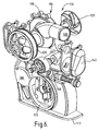
- FIGURE 4 is an isometric view of the front of the housing shown in Figures 1, 2 and 3;
- FIGURE 5 is an isometric view of an integral body forming the housing shown in Figure 4;
- FIGURE 6 is an exploded isometric view of a further embodiment of a housing according to the invention;
- FIGURE 7 is a schematic front elevation view of a pump housing comprising a lubricant filtration system according to the invention;
- FIGURE 8 is a schematic sectional side elevation view of the filter housing shown in Figure 7; and
- FIGURE 9 is a schematic side elevation view of the pump housing shown in Figure 7 comprising the filter housing shown in Figure 8.
-
- Referring to the drawings, there is shown a
housing 10 according to the invention comprising anintegral body 11 having anexternal face 12 and internal orcontact face 14 for mating with or mounting on an engine block.Housing 10 further comprises a water orcoolant pump 16, alubricant cooler 18 and a lubricant oroil pump 20. Thehousing 10 is adapted for mounting on to an engine block about a crankshaft and is provided with anaperture 13 defined by arim 15 for carrying a crankshaft seal.Housing 10 further comprises alower face 17 for abutting an oil sump casing for example, and abolt 19 for attachment of an idler pulley if so required. - Referring to Figure 1 in detail, there is shown a
recess 22 forming part ofwater pump 16. Thewater pump 16 is further defined by acentral bore 24 for a drive shaft, preferably having an integral bearing, from a pulley 25 (see Figures 2 and 4), and arecess 26 for a pump rotor comprising for example impeller blades (not shown). Aninlet 28 is provided for coolant such as water into thehousing 10, which coolant is communicated to thepump 16 via an opening 30proximal recess 26 for the pump rotor. The pump rotor can comprise radial impeller blades for example which cause coolant from opening 30 to be forced outwardly to first and second radiallyouter volutes second outlets second volutes -
Outlet 36 preferably leads directly to an inlet aperture within the engine block hence enabling circulation of coolant within the engine block. - However,
outlet 38 communicates with a passageway section ortube 40 forming part of a coolant flow passageway whichtube 40 connects to ashaped cover plate 42 which is mounted using co-operating flanges withbody 11 ofhousing 10.Plate 42 directs flow of coolant along the direction of arrow W towards a further section of the coolant flow passageway in the form ofcylindrical section 44 which is adapted to take an oil cooler as described later. Coolant or water continues to flow in the direction of arrows W towards a secondshaped cover plate 46 which directs water back intohousing body 11 through afurther passageway section 48 comprising a tubular section and bore defined withinbody 11 whichsection 48 leads to anoutlet 50. Again, coolant can communicate with an opening in an engine block viaoutlet 50. - Accordingly, the double volute is split into two volutes, 34 and 32, whereby volute 32 diverts flow into the engine block via
outlet 36. Volute 34 delivers flow throughtube 40 and into thecooler bore 44 before entering the block atoutlet 50 and merging with the flow fromorifice 36. - Preferably, the pressures at
outlets - Beneficially,
outlets housing 10. - Beneficially, a heat exchanger (not shown) can be provided for oil within the
pump housing 10. In a preferred form, a fin and plate cooler is provided which is connected withincylindrical section 44 to anoil inlet 52 and oil outlet 54 thereby enabling cooling of oil passing through the cooler due to the flow of coolant in the direction of arrows W throughcylindrical section 44, and hence over the fin and plate cooler.Section 44 can be defined in part by a wall which whenhousing 10 is mounted on the engine block defines a gallery into which oil is fed from the engine block through anaperture 52 therein. Outlet aperture 54 can be defined in the wall betweensection 44 and the gallery. The oil from outlet 54 can pass back into the engine block. However, the inlet or outlet could however, feed directly from or to theoil pump 20. - Referring now to the
oil pump 20 in more detail, it can be seen in Figure 1 that a recess orchamber 56 is provided for a pump (not shown) such as a rotor pump driven by a drive shaft (not shown) which shaft can be located within recess 58.Pump 20 comprises aninlet 60 which preferably mates with an outlet on the engine block to feed oil intopump 20 or an inlet pipe from a pump on the engine block for example. Oil is then pumped via anoutlet 62 back into the engine block. Acover plate 68 is used to enclosepump 20 as can be seen in Figures 2, 4 and 5 for example. Beneficially, afurther inlet 64 can be provided to re-circulate oil from apressure relief valve 66. The feed to therelief valve 66 can be direct to an oil passageway section in the engine block which is in fluid contact with achamber 65 in thehousing body 11 for example. - Referring to Figure 6 there is shown a second embodiment of a
pump housing 110 according to the invention which is substantially similar to thehousing 10. Accordingly, like components are given the same two digit reference numbers prefixed with the number 1.Housing 110 comprises acoolant inlet 128 which feeds to acoolant pump 116 which comprises arotor 123 having impeller blades for effecting movement of the coolant whenrotor 123 is caused to rotate due to the rotation ofpulley 125. A furtheridler pulley 127 is provided adjacent pulley 125 (if required) whilst a series ofapertured lugs 119 is provided to facilitate mounting ofhousing 110 onto an engine block. - Referring to Figures 7, 8 and 9, there is shown a modified
pump housing 10 comprising alubricant filtration system 80 having afilter housing 82 with acap 84. Thecap 84 can for example be screw mountable into the top ofcylindrical housing 82 thereby to locate a cylindrical filter cartridge within thefilter housing 82. Thefilter system 80 comprises anoil inlet aperture 86 abuttable against a feed passageway from the engine block. Preferably theinlet aperture 86 is surrounded by a seal such as an o-ring seal 88 mounted in the face of an annularflange surrounding aperture 86. Internally, thefilter housing 82 preferably comprises a outlet flange which projects upwardly into a cavity for containing acartridge filter 94. The upper end of theannular flange 90 preferably carries aseal 92 to prevent communication between the incoming unfiltered, and outgoing filtered lubricant. Accordingly,annulus 90 comprises an outlet aperture andpassageway 96 which preferably leads to alubricant cooler 98 such as a tubular cooler or fin and plate cooler as described earlier. - In an alternative form, the
filtration system 80 forms part of the engine casing or block and provides suitable inlet and outlet apertures for communication with the pump housing.
Claims (14)
- A pump housing for mounting on an internal combustion engine block comprising an integral body having a recess for a coolant pump and a passageway for communicating coolant between an inlet to and outlet from the coolant pump, and a recess for a lubricant pump and a passageway for communicating lubricant between an inlet to and outlet from the lubricant pump.
- A pump housing according to Claim 1 further comprising a heat exchanger for lubricant.
- A pump housing according to Claim 2 wherein the heat exchanger comprises a cooler such as a fin and plate cooler.
- A pump housing according to Claim 3 wherein the heat exchanger is cooled by coolant pumped by the coolant pump.
- A pump housing according to Claim 4 wherein a passageway for the coolant pump enables flow of coolant over the lubricant heat exchanger.
- A pump housing according to any preceding claim comprising two or more separate flow passageways for coolant within the housing.
- A pump housing according to Claim 6 comprising two outlets from the coolant pump enabling pumped coolant to be directed in two separate directions.
- A pump housing according to Claim 7 and Claim 2 wherein one of the outlets enables flow of coolant over the lubricant heat exchanger.
- A pump housing according to any preceding claim which further comprises a lubricant pressure relief valve and communicating passageway to enable re-circulation of lubricant from the relief valve back to the lubricant pump.
- A coolant pump housing having a body which defines a recess for a coolant pump and further defining two separate passageways to or from the pump to enable separate flow of coolant along two different paths within the housing.
- A coolant pump housing according to Claim 10 comprising two outlets from the coolant pump.
- A pump housing according to any preceding claim comprising an integral lubricant filtration system.
- A pump housing for mounting on an internal combustion engine block which housing comprises an integral lubricant filtration system.
- A pump housing according to Claim 12 or 13 wherein the oil filtration system comprises a filter housing integrally mounted within the pump housing and operably having suitable inlet and outlet passageways to direct oil into the filter housing.
Applications Claiming Priority (4)
| Application Number | Priority Date | Filing Date | Title |
|---|---|---|---|
| GB9914696 | 1999-06-23 | ||
| GBGB9914696.1A GB9914696D0 (en) | 1999-06-23 | 1999-06-23 | Improvements in pump housings for internal combustion engines |
| GB9917122 | 1999-07-21 | ||
| GBGB9917122.5A GB9917122D0 (en) | 1999-06-23 | 1999-07-21 | Improvements in pump housings for internal combustion engines |
Publications (2)
| Publication Number | Publication Date |
|---|---|
| EP1063397A2 true EP1063397A2 (en) | 2000-12-27 |
| EP1063397A3 EP1063397A3 (en) | 2002-04-10 |
Family
ID=26315696
Family Applications (1)
| Application Number | Title | Priority Date | Filing Date |
|---|---|---|---|
| EP00305246A Withdrawn EP1063397A3 (en) | 1999-06-23 | 2000-06-21 | Pump housing for internal combustion engine |
Country Status (10)
| Country | Link |
|---|---|
| EP (1) | EP1063397A3 (en) |
| JP (1) | JP2001020712A (en) |
| KR (1) | KR20010007490A (en) |
| CN (1) | CN1280246A (en) |
| AU (1) | AU4261500A (en) |
| BR (1) | BR0002860A (en) |
| CA (1) | CA2312604A1 (en) |
| GB (1) | GB2351322A (en) |
| ID (1) | ID26426A (en) |
| NO (1) | NO20003274L (en) |
Cited By (3)
| Publication number | Priority date | Publication date | Assignee | Title |
|---|---|---|---|---|
| EP1211391A1 (en) * | 2000-12-01 | 2002-06-05 | Honda Giken Kogyo Kabushiki Kaisha | Housing to be affixed to an engine |
| DE202004011114U1 (en) * | 2004-07-14 | 2005-11-24 | Hengst Gmbh & Co.Kg | Oil module with water pump and heat exchanger |
| DE202004018136U1 (en) * | 2004-07-14 | 2005-11-24 | Daimlerchrysler Ag | Oil-coolant module |
Families Citing this family (6)
| Publication number | Priority date | Publication date | Assignee | Title |
|---|---|---|---|---|
| DE102008013675B4 (en) * | 2008-03-11 | 2017-12-14 | Dr. Ing. H.C. F. Porsche Aktiengesellschaft | Internal design of the housing of a coolant pump with multiple outlet channels |
| DE112009000861T5 (en) * | 2008-04-17 | 2011-04-07 | Borgwarner Inc., Auburn Hills | Coolant pump |
| CN101592074B (en) * | 2009-06-30 | 2011-01-05 | 重庆海通投资集团有限公司 | Front end cover assembly for integrated lubrication cooling power pump of engine |
| US8601997B2 (en) | 2010-05-17 | 2013-12-10 | GM Global Technology Operations LLC | Water pump with integrated oil cooler |
| FR2965865B1 (en) * | 2010-10-12 | 2016-12-30 | Soc De Motorisations Aeronautiques | OIL FILTERING AND DISPENSING DEVICE FOR SUPPLYING TWO OIL PUMPS TO AN AIRCRAFT ENGINE |
| JP2014125930A (en) * | 2012-12-26 | 2014-07-07 | Honda Motor Co Ltd | Casing structure of water-cooled internal combustion engine |
Citations (4)
| Publication number | Priority date | Publication date | Assignee | Title |
|---|---|---|---|---|
| US3743011A (en) * | 1971-11-04 | 1973-07-03 | Modine Mfg Co | Heat exchanger |
| US4370957A (en) * | 1980-01-24 | 1983-02-01 | Hans List | Assembly of auxiliary equipment for a water-cooled internal combustion engine |
| US4977870A (en) * | 1989-02-17 | 1990-12-18 | Nissan Motor Co., Ltd. | Internal combustion engine |
| DE4211896A1 (en) * | 1992-04-09 | 1993-10-14 | Daimler Benz Ag | End cover plate for IC engine - has internal chamber for oil cooler with passages for connection to oil pump and coolant pump |
Family Cites Families (7)
| Publication number | Priority date | Publication date | Assignee | Title |
|---|---|---|---|---|
| DE3312490A1 (en) * | 1983-04-07 | 1984-10-11 | Flutec Fluidtechnische Geräte GmbH, 6603 Sulzbach | DEVICE FOR CONNECTING EVERY HOUSING OF A DRIVE MOTOR AND A PUMP |
| US4738584A (en) * | 1986-07-28 | 1988-04-19 | Carl Price | Multiple impeller pump |
| GB2205611B (en) * | 1987-06-09 | 1991-08-21 | Austin Rover Group | A pump assembly for a motor vehicle. |
| GB2239049B (en) * | 1989-11-30 | 1993-11-24 | Rover Group | A pump assembly |
| FR2665223B1 (en) * | 1990-07-26 | 1994-07-08 | Snecma | METHOD FOR SIMULTANEOUSLY DRIVING TWO DIFFERENT REGIMEN PUMPS AND TURBOPUMP FOR SIMULTANEOUSLY COMPRESSING TWO FLUIDS. |
| JP3286472B2 (en) * | 1994-09-02 | 2002-05-27 | ヤンマーディーゼル株式会社 | Internal combustion engine gear case |
| GB2322416B (en) * | 1997-02-22 | 2000-11-01 | Rover Group | A pump assembly |
-
2000
- 2000-06-13 GB GB0014238A patent/GB2351322A/en not_active Withdrawn
- 2000-06-21 EP EP00305246A patent/EP1063397A3/en not_active Withdrawn
- 2000-06-22 NO NO20003274A patent/NO20003274L/en not_active Application Discontinuation
- 2000-06-23 JP JP2000189830A patent/JP2001020712A/en active Pending
- 2000-06-23 CN CN00118738A patent/CN1280246A/en active Pending
- 2000-06-23 KR KR1020000034671A patent/KR20010007490A/en not_active Application Discontinuation
- 2000-06-23 BR BR0002860-6A patent/BR0002860A/en not_active Application Discontinuation
- 2000-06-23 ID IDP20000516D patent/ID26426A/en unknown
- 2000-06-23 CA CA002312604A patent/CA2312604A1/en not_active Abandoned
- 2000-06-23 AU AU42615/00A patent/AU4261500A/en not_active Abandoned
Patent Citations (4)
| Publication number | Priority date | Publication date | Assignee | Title |
|---|---|---|---|---|
| US3743011A (en) * | 1971-11-04 | 1973-07-03 | Modine Mfg Co | Heat exchanger |
| US4370957A (en) * | 1980-01-24 | 1983-02-01 | Hans List | Assembly of auxiliary equipment for a water-cooled internal combustion engine |
| US4977870A (en) * | 1989-02-17 | 1990-12-18 | Nissan Motor Co., Ltd. | Internal combustion engine |
| DE4211896A1 (en) * | 1992-04-09 | 1993-10-14 | Daimler Benz Ag | End cover plate for IC engine - has internal chamber for oil cooler with passages for connection to oil pump and coolant pump |
Cited By (4)
| Publication number | Priority date | Publication date | Assignee | Title |
|---|---|---|---|---|
| EP1211391A1 (en) * | 2000-12-01 | 2002-06-05 | Honda Giken Kogyo Kabushiki Kaisha | Housing to be affixed to an engine |
| DE202004011114U1 (en) * | 2004-07-14 | 2005-11-24 | Hengst Gmbh & Co.Kg | Oil module with water pump and heat exchanger |
| DE202004018136U1 (en) * | 2004-07-14 | 2005-11-24 | Daimlerchrysler Ag | Oil-coolant module |
| US8783216B2 (en) | 2004-07-14 | 2014-07-22 | Hengst Gmbh & Co. Kg | Oil/coolant module with coolant treatment system |
Also Published As
| Publication number | Publication date |
|---|---|
| KR20010007490A (en) | 2001-01-26 |
| JP2001020712A (en) | 2001-01-23 |
| BR0002860A (en) | 2001-01-30 |
| NO20003274L (en) | 2000-12-27 |
| NO20003274D0 (en) | 2000-06-22 |
| EP1063397A3 (en) | 2002-04-10 |
| ID26426A (en) | 2000-12-28 |
| AU4261500A (en) | 2001-01-04 |
| CA2312604A1 (en) | 2000-12-23 |
| GB0014238D0 (en) | 2000-08-02 |
| GB2351322A (en) | 2000-12-27 |
| CN1280246A (en) | 2001-01-17 |
Similar Documents
| Publication | Publication Date | Title |
|---|---|---|
| US5704761A (en) | Full-circumferential flow pump | |
| US4563124A (en) | Double suction, single stage volute pump | |
| US7219645B2 (en) | Oil pump for a motorcycle | |
| US7174998B2 (en) | Submerged electric fluid pump | |
| US20030012664A1 (en) | Multi-stage internal gear fuel pump | |
| EP1063397A2 (en) | Pump housing for internal combustion engine | |
| CN109469609B (en) | Oil pump and engine lubricating system | |
| US6478559B2 (en) | Balanced vane pump | |
| US6499964B2 (en) | Integrated vane pump and motor | |
| JPH10159525A (en) | Oil feeder for engine | |
| US4703726A (en) | Lubricating system for engine | |
| CN102628464A (en) | Integrated motor vane pump hydraulic power unit | |
| US4826410A (en) | Cooling systems for rotary piston engines | |
| US20040191092A1 (en) | Multiple pump housing | |
| KR20050114736A (en) | Radial piston pump | |
| US20060254860A1 (en) | Mounting structure of oil pump | |
| EP1310679B1 (en) | Pump having multiple volute passages and method of pumping fluid | |
| JPH081129B2 (en) | Engine oil cooling system for water-cooled 4-cycle engine | |
| EP2131032A1 (en) | Engine fluid pump and timing gear housing | |
| TW475965B (en) | Improvements in pump housing for internal combustion engines | |
| JPS63246482A (en) | Oil pump | |
| JPH11270489A (en) | Structure of double barrel multistage pump | |
| JPH0536110Y2 (en) | ||
| CA2549665C (en) | Coolant pump with axial output | |
| US6474965B2 (en) | Rotary piston engine having a cogwheel pump and an oil metering pump |
Legal Events
| Date | Code | Title | Description |
|---|---|---|---|
| PUAI | Public reference made under article 153(3) epc to a published international application that has entered the european phase |
Free format text: ORIGINAL CODE: 0009012 |
|
| AK | Designated contracting states |
Kind code of ref document: A2 Designated state(s): AT BE CH CY DE DK ES FI FR GB GR IE IT LI LU MC NL PT SE |
|
| AX | Request for extension of the european patent |
Free format text: AL;LT;LV;MK;RO;SI |
|
| PUAL | Search report despatched |
Free format text: ORIGINAL CODE: 0009013 |
|
| AK | Designated contracting states |
Kind code of ref document: A3 Designated state(s): AT BE CH CY DE DK ES FI FR GB GR IE IT LI LU MC NL PT SE |
|
| AX | Request for extension of the european patent |
Free format text: AL;LT;LV;MK;RO;SI |
|
| AKX | Designation fees paid | ||
| REG | Reference to a national code |
Ref country code: DE Ref legal event code: 8566 |
|
| STAA | Information on the status of an ep patent application or granted ep patent |
Free format text: STATUS: THE APPLICATION IS DEEMED TO BE WITHDRAWN |
|
| 18D | Application deemed to be withdrawn |
Effective date: 20021011 |