EP1211386B1 - Anneau d'étanchéité pour turbines et turbine associée - Google Patents
Anneau d'étanchéité pour turbines et turbine associée Download PDFInfo
- Publication number
- EP1211386B1 EP1211386B1 EP01310031A EP01310031A EP1211386B1 EP 1211386 B1 EP1211386 B1 EP 1211386B1 EP 01310031 A EP01310031 A EP 01310031A EP 01310031 A EP01310031 A EP 01310031A EP 1211386 B1 EP1211386 B1 EP 1211386B1
- Authority
- EP
- European Patent Office
- Prior art keywords
- turbine
- sealing ring
- disk
- arm
- interstage
- Prior art date
- Legal status (The legal status is an assumption and is not a legal conclusion. Google has not performed a legal analysis and makes no representation as to the accuracy of the status listed.)
- Expired - Lifetime
Links
Images


Classifications
-
- F—MECHANICAL ENGINEERING; LIGHTING; HEATING; WEAPONS; BLASTING
- F01—MACHINES OR ENGINES IN GENERAL; ENGINE PLANTS IN GENERAL; STEAM ENGINES
- F01D—NON-POSITIVE DISPLACEMENT MACHINES OR ENGINES, e.g. STEAM TURBINES
- F01D11/00—Preventing or minimising internal leakage of working-fluid, e.g. between stages
- F01D11/001—Preventing or minimising internal leakage of working-fluid, e.g. between stages for sealing space between stator blade and rotor
-
- F—MECHANICAL ENGINEERING; LIGHTING; HEATING; WEAPONS; BLASTING
- F01—MACHINES OR ENGINES IN GENERAL; ENGINE PLANTS IN GENERAL; STEAM ENGINES
- F01D—NON-POSITIVE DISPLACEMENT MACHINES OR ENGINES, e.g. STEAM TURBINES
- F01D5/00—Blades; Blade-carrying members; Heating, heat-insulating, cooling or antivibration means on the blades or the members
- F01D5/02—Blade-carrying members, e.g. rotors
- F01D5/08—Heating, heat-insulating or cooling means
- F01D5/081—Cooling fluid being directed on the side of the rotor disc or at the roots of the blades
-
- F—MECHANICAL ENGINEERING; LIGHTING; HEATING; WEAPONS; BLASTING
- F05—INDEXING SCHEMES RELATING TO ENGINES OR PUMPS IN VARIOUS SUBCLASSES OF CLASSES F01-F04
- F05D—INDEXING SCHEME FOR ASPECTS RELATING TO NON-POSITIVE-DISPLACEMENT MACHINES OR ENGINES, GAS-TURBINES OR JET-PROPULSION PLANTS
- F05D2240/00—Components
- F05D2240/55—Seals
-
- Y—GENERAL TAGGING OF NEW TECHNOLOGICAL DEVELOPMENTS; GENERAL TAGGING OF CROSS-SECTIONAL TECHNOLOGIES SPANNING OVER SEVERAL SECTIONS OF THE IPC; TECHNICAL SUBJECTS COVERED BY FORMER USPC CROSS-REFERENCE ART COLLECTIONS [XRACs] AND DIGESTS
- Y02—TECHNOLOGIES OR APPLICATIONS FOR MITIGATION OR ADAPTATION AGAINST CLIMATE CHANGE
- Y02T—CLIMATE CHANGE MITIGATION TECHNOLOGIES RELATED TO TRANSPORTATION
- Y02T50/00—Aeronautics or air transport
- Y02T50/60—Efficient propulsion technologies, e.g. for aircraft
Definitions
- the present invention relates to gas turbine engines having a multi-stage turbine. More particularly, the present invention relates to an interstage sealing and torque ring for disposition between adjacent stages in a gas turbine engine having a multi-stage turbine.
- Gas turbine engines having multiple turbine stages include sealing arrangements between adjacent stages for improved operating efficiency.
- the sealing arrangements are directed to confining the flow of hot combustion gases to flow in an annular path around and between the stationary turbine stator blades, or nozzles, and also around and between the adjacent rotor blades.
- such sealing arrangements also serve to confine and to direct cooling air that is provided to cool the turbine disks, the turbine blade roots, and also the interior of the rotor blades themselves.
- providing rotor blade cooling passages allows higher turbine inlet temperatures, which results in higher thermal efficiency of the engine and higher power or thrust output.
- the air for cooling the turbine rotor blades must be suitably confined and directed so that it is not dissipated by passing into the hot gas stream, but, instead, passes over and through the surfaces and structures intended to be cooled, and so that it also passes into the rotor blade internal passageways to provide the desired rotor blade cooling effect.
- the sealing arrangement be capable of accommodating axial and radial movements of the turbine stage elements during engine operation.
- the several elements are subjected to a range of different loadings and different rates of expansion based upon local part temperatures and also based upon engine and aircraft operating conditions.
- a turbine interstage sealing member that can provide an effective seal to confine combustion gases to flow in a desired annular channel, to separate combustion gases from cooling air flows, and to do so with a unitary structural arrangement that facilitates assembly of a multi-stage turbine and that is also capable of responding to thermally- and mechanically-induced size and orientation changes of the turbine structural elements.
- an interstage sealing ring is provided according to claim 1, as well as a multi-stage turbine according to claim 9.
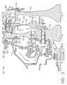
- Core engine 12 includes a generally tubular outer casing 16 that defines an annular core engine inlet 18 and that encloses and supports a low pressure booster 20 for raising the pressure of the air that enters core engine 12 to a first pressure level.
- a high pressure, multi-stage, axial-flow compressor 22 receives pressurized air from booster 20 and further increases the pressure of the air.
- the pressurized air flows to a combustor 24 in which fuel is injected into the pressurized air stream, and the fuel-air mixture is ignited to raise the temperature and energy level of the pressurized air.
- the high energy combustion products flow to a first turbine 26 for driving compressor 22 through a first drive shaft 28, and then to a second turbine 30 for driving booster 20 through a second drive shaft 32 that is coaxial with first drive shaft 28. After driving each of turbines 26 and 30, the combustion products leave core engine 12 through an exhaust nozzle 34 to provide propulsive jet thrust.
- Fan section 14 includes a rotatable, axial-flow fan rotor 36.
- An annular fan casing 38 surrounds fan rotor 36 and is supported from core engine 12 by a plurality of substantially radially-extending, circumferentially-spaced support struts 44.
- Fan rotor 36 carries a plurality of radially-extending, circumferentially spaced fan blades 42.
- Fan casing 38 extends rearwardly from fan rotor 36 over an outer portion of core engine 12 to define a secondary, or bypass airflow conduit.
- a casing element 39 that is downstream of and connected with fan casing 38 supports a plurality of fan stream outlet guide vanes 40. The air that passes through fan section 14 is propelled in a downstream direction by fan blades 42 to provide additional propulsive thrust to supplement the thrust provided by core engine 12.
- Turbine 50 includes a first stage turbine rotor that is defined by a rotor disk 52 that has an enlarged hub 54, and an outer periphery 56 that carries a plurality of circumferentially-spaced first stage rotor blades 58.
- a second stage turbine rotor Spaced axially downstream from and adjacent to first stage turbine disk 52 is a second stage turbine rotor that is defined by a rotor disk 60 that also includes an enlarged hub 62, and that has an outer periphery 64 on which are carried a plurality of circumferentially-spaced, second stage rotor blades 66.
- Second stage disk 60 includes an axially-forwardly-extending annular drive ring 68 that carries a radially-inwardly-directed flange 70 that includes a plurality of circularly-distributed bolt holes 72. Connecting bolts 74 extend through bolt holes 72 and through corresponding bolt holes 76 provided in first stage disk 52 for interconnecting first and second stage turbine disks 52, 60 so that they rotate together. Additionally, first stage disk 52 includes an integral, forwardly-extending, annular drive shaft 78 that is drivingly connected with the core engine compressor.
- first stage turbine nozzle 80 Positioned upstream of first stage turbine disk 52 and radially adjacent first stage rotor blades 58 is a first stage turbine nozzle 80.
- Nozzle 80 includes an annular inner ring 82 and an annular outer ring (not shown) between which are positioned a plurality of radially-extending, circumferentially-spaced, stationary first stage nozzle vanes 84.
- First stage nozzle inner ring 82 is suitably connected with a generally radially-inwardly-extending ring 86 that carries an annular abradable seal 88 on its inner periphery for sealing engagement with a labyrinth seal 90 forming part of an axially-extending, outer sealing ring 92.
- An inner sealing ring 91 that is radially-inwardly spaced from outer sealing ring 92 includes a labyrinth seal 93 that is in sealing engagement with an annular abradable seal 95. Sealing rings 91 and 92 are each connected with and rotate with first stage turbine disk 52.
- Nozzle 94 includes an inner annular ring 96 and an outer annular ring (not shown) between which are carried a plurality of radially-extending, circumferentially-spaced, stationary second stage nozzle vanes 98.
- first stage turbine nozzle 80 which directs the gases against first stage turbine blades 58 to rotate first stage turbine disk 52.
- the gases that exit from first stage turbine blades 58 enter second stage turbine nozzle 94, which directs the gasses against second stage turbine blades 66 to rotate second stage turbine disk 60.
- first stage nozzle 80 includes an axially-rearwardly-extending sealing lip 100.
- Lip 100 is positioned adjacent to and forward of a cooperating, forwardly-extending sealing lip 102 carried by first stage disk 52.
- Sealing lip 102 is defined by forward extensions of the blade platforms of each of first stage turbine rotor blades 58, and also by forwardly-extending elements of damper seals (not shown) carried by first stage disk 52 in the spaces between adjacent blades and the disk outer periphery.
- Each of nozzle sealing lip 100 and rotor forward sealing lip 102 define annular sealing rings that overlap each other in a radial direction so that combustion gases pass through the flow channel defined between the overlapped sealing lips and the turbine outer casing.
- Similar annular sealing rings are provided between first stage turbine rotor blades 58 and second stage nozzle 94.
- a pair-of sealing rings are defined by a plurality of radially-spaced, rearwardly-extending sealing lips 104, 106 on first stage rotor blades 58. Sealing lips 104, 106 cooperate with an annular second stage nozzle forward sealing lip 108 that extends into the space between sealing lips 104, 106 to block the inward flow of combustion gases.
- second stage nozzle 94 and second stage turbine blades 66 a similar sealing arrangement is provided by second stage nozzle aft sealing lip 110 and second stage turbine blade forward sealing lip 117, which are also in overlapped relationship in a radial direction.
- Ring 112 extends between and is in contact with the aft face of first stage turbine disk 52 and with the forward face of second stage turbine disk 60.
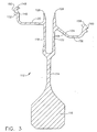
- Sealing ring 112 is a substantially "T"-shaped member in cross section and includes a disk-shaped, radially-extending body member 114 that is positioned between an enlarged hub 116 and an outer section that is defined by a forward radial arm 118, from which a forward axial arm 120 extends is an upstream direction, and an aft radial arm 122, from which an aft, generally axial arm 124 extends in a downstream direction.
- Forward radial arm 118 and aft radial arm 122 are spaced from each other in an axial direction, relative to the engine longitudinal axis, and they can be parallel to each other as shown and have a relatively thin cross section. Forward and aft radial arms 118, 122 can independently deflect, relative to body 114, in a fore and aft direction of the turbine, in the manner of cantilever beams supported by body 114, to respond movement of the turbine parts relative to each other resulting from thermal and mechanical loads imposed upon the respective turbine stages during engine operation.
- the outer periphery of forward radial arm 118 includes a circumferentially-extending seal tooth 126 and the outer periphery of aft radial arm 122 includes a similar circumferentially-extending seal tooth 128.
- Each of seal teeth 126, 128 is adapted to engage with an annular abradable seal member 130 carried on inner nozzle ring 96 of second stage turbine nozzle 94 to provide an outer interstage seal.
- First stage turbine disk 52 includes a plurality of circularly-disposed, axially-extending cooling air passageways 132 that pass completely through disk 52. Passageways 132 are positioned radially outwardly of connecting bolt holes 76 and between sealing rings 91 and 92. A plurality of openings 134 are provided in and extend through radial connecting leg 136 of sealing ring 92, which is clamped against the forward face of first stage turbine disk 52 by a radially-extending leg of inner sealing ring 91.
- annular cooling air duct 138 Positioned immediately upstream of openings 134 is an annular cooling air duct 138 defined by an outer annular ring 140 and radially-inwardly-spaced inner annular ring 142, and to which bleed air from the compressor (see Figure 1 ) is conveyed.
- the relatively cool bleed air passes through openings 134 in sealing ring 92 and through cooling air passageways 132 in first stage disk 52, into cooling air chamber 144 that is defined by the volume between first and second stage turbine disks 52, 60 and arms 120, 124 of interstage sealing ring 112.
- cooler compressor bleed air enters cooling air chamber 144 and can be utilized for cooling turbine rotor disks 52, 60, as well as turbine rotor blades 58, 66, as will be explained hereinafter.
- forward axial arm 120 of interstage sealing ring 112 is substantially perpendicular to forward radial arm 118.
- axial arm 120 can be oriented at an acute angle that is defined by the included angle between axial arm 120 and radial arm 118.
- axial arm 120 can be curved, if desired.
- axial arm 120 is preferably such that its outer end can deflect radially and axially, relative to the turbine longitudinal axis, in response to thermal and mechanical loads imposed on sealing ring 112 and on turbine disk 52, so that the outer end of arm 120 is maintained in contact with the downstream surface of turbine disk 52.
- forward axial arm 120 includes a substantially radially-extending flange 146 that carries a forward disk engagement member 148.
- Engagement member 148 includes an annular, substantially radially-extending disk engagement surface 150, and a plurality of axially-forwardly-extending and circularly-disposed projections 152 with intervening slots. The projections on engagement member 148 contact axial projections (not shown) carried by rotor blades 58 to limit relative rotation between first stage disk 52 and interstage sealing ring 112.
- Aft arm 124 extends outwardly from aft radial arm 122 at a radial position that is spaced inwardly, relative to hub 116, as compared with the radial position at which forward axial arm 120 extends from forward radial arm 118.
- Aft arm 124 includes an inclined section 154 and a generally-axially-extending section 156. Inclined section 154 can be disposed relative to radial arm 122 at an included acute angle of about 45°, although the precise angle of inclination can be varied, if desired.
- Aft disk engagement member 158 carried at the outermost end of aft arm 124 is positioned opposite and in contact with the second stage disk and the shank areas of the second stage rotor blades.
- Aft disk engagement member 158 includes an annular, substantially radially-extending disk engagement surface 160 for engagement with the forward face of second stage turbine disk 60 and the second stage rotor blade shanks.
- the included obtuse angle between inclined section 154 and generally-axially-extending section 156 can be of the order of about 140°. Again, however, the precise angle of inclination can be varied, if desired, and is generally based upon the radial point of contact of aft arm 124 with turbine disk 60. In that regard, the point of connection between inclined section 154 and radial arm 122, the angle of inclination of inclined section 154 relative to radial arm 122, and the relative lengths and thicknesses of arm sections 154 and 156 are selected to allow aft arm 124 to deflect radially and axially, relative to the turbine longitudinal axis.
- aft disk engagement member 158 remains in contact with the forward surface of disk 60, and also with the shanks of the rotor blades carried thereby, in response to relative movement of the turbine parts that occurs as a result of changes in thermal and mechanical loads imposed on the turbine during engine operation.
- interstage sealing ring 112 is such as to provide tight engagement of the respective disk engagement surfaces 150, 160 with the first and second turbine disks and blades, to substantially seal cooling air chamber 144 between turbine disks 52 and 60.
- Forward radial arm 118 and aft radial arm 122 are each thinner in an axial direction than is body member 114, to allow deflection of the outer portions of radial arms 118, 122 in an axial direction of the turbine, to respond to dimensional changes between first and second stage turbine disks 52, 60 as a result of expansion and contraction of the turbine parts resulting from changing thermal and mechanical loading conditions on the turbine over the operating range of the engine.
- sufficient preload is preferably provided between annular engagement surfaces 150, 160 and the respective turbine disks so that contact therebetween is maintained even if the axial spacing between the opposed surfaces of the turbine disks increases during engine operation.
- the flexural characteristics of forward and aft radial arms 118, 122, respectively allow deflection of those arms to occur to accommodate such spacing decreases.
- radial arms 118, 122 act as cantilever beams that are subjected to a concentrated load.
- each of forward disk engagement member 148 and aft disk engagement member 158 is capable of radial movement, relative to the turbine longitudinal axis, as a result of deflection of arms 120 and 124, again, to respond to expansion or contraction of the turbine parts in a radial direction caused by thermal and mechanical loading effects.
- forward axial arm 120 and forward radial arm 118 can deflect under load to allow combined radial and axial movement of forward disk engagement member 148
- aft arm 124 and aft radial arm 122 can deflect under load to allow both radial and axial movement of aft disk engagement member 158.
- first stage rotor blades 58 are positioned on a blade platform 164, the axially-extending outermost ends of which define forward sealing lip 102 and aft sealing lips 104, 106.
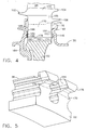
- a blade shank 166 which is of a generally dovetail-shaped configuration in axial cross section, to allow it to be axially slidably received within a correspondingly-shaped dovetail slot 168 provided in first stage first stage disk 52 (see Figure 5 ).
- Dovetail slot 168 is defined by the peripheral spaces between adjacent, circumferentially-spaced disk posts 170.
- Blade shanks 166 each also include an axially-extending projection 172 that is carried on the aft face 174 of blade shank 166 and that is received in a respective gap between adjacent axial projections 152 carried on forward disk engagement member 148 of interstage ring 112.
- the contact between projections 172 carried by the blade shanks and projections 152 carried by interstage sealing ring 112 serve to limit relative rotation between the first stage rotor and sealing ring 112.
- Blade shanks 166 are held against movement in a peripheral direction relative to first stage disk 52 by respective adjacent disk posts 170, each of which includes an axially-rearwardly-extending post extension 176.
- Blade shanks 166 have a depth in a radial direction, relative to first stage disk 52, that is less than the radial depth of dovetail slot 168, to provide an axially-extending cooling air passageway 178 therebetween.
- Cooling air passageway 178 extends between blade shank bottom face 180 and dovetail slot bottom wall 182 and receives cooling air that flows from cooling air chamber 144 (see Figure 2 ).
- the cooling air can pass through radially-extending channels (not shown) provided in blade shank 166 and into the airfoil portion of first stage rotor blade 58 to provide cooling air to the first stage blades.
- annular engagement surface 150 of forward disk engagement member 148 of the interstage sealing ring bears against the aft faces 174 of blade shanks 166, and also against the aft faces of disk posts 170.
- disk engagement member 148 provides a blade retention function to block rearward movement blade shanks 166.
- the uppermost annular surface of forward disk engagement member 148 bears against the lower annular face of post extension 176 to limit radial outward movement interstage sealing ring 112.
- a forward blade retainer 184 is provided in the form of an annular disk that lies against the forward face of first stage disk 52.
- Forward blade retainer 184 includes a plurality of axially-extending, radially-spaced engaging ridges 186 that engage with the forward faces 188 of blade shanks 166 and the forward faces of adjacent disk posts 170.
- a seal wire 189 is carried in the annular space between engaging ridges 186 to maintain an air seal, to prevent cooling air from passing between blade retainer 184 and blade shanks 166.
- cooling air flows in the directions shown by the several arrows in Figure 2 , from interstage cooling air chamber 144 into cooling air passageway 178, and then into cooling passageways (not shown) within the shanks and the airfoil portions of each of first stage blades 58.
- forward blade retainer 184 is held in position by a split ring 190 that is positioned between forward blade retainer 184 and a radial lip 192 carried by disk 52. Lip 192 is spaced axially forwardly of and extends radially relative to first stage turbine disk 52.
- second stage rotor blades 66 are positioned on a blade platform 194, the axially-extending forward end of which defines forward sealing lip 117.
- a blade shank 196 which is of a generally dovetail-shaped configuration in axial cross section to allow it to be axially slidably received within a correspondingly-shaped dovetail slot 198 provided in second stage rotor disk 60 (see Figure 7 ).
- Dovetail slot 198 is defined by the peripheral spaces between adjacent, circumferentially-spaced disk posts 200.
- Blade shanks 196 are held against movement in a peripheral direction relative to rotor disk 60 by respective adjacent disk posts 200, each of which includes an axially-forwardly-extending post extension 206.
- Blade shanks 196 have a depth in a radial direction, relative to rotor disk 60, that is less than the radial depth of dovetail slot 198, to provide an axially-extending cooling air passageway 208 therebetween.
- Cooling air passageway 208 extends between blade shank bottom face 210 and dovetail slot bottom wall 212 and receives cooling air that flows from cooling air chamber 144 (see Figure 2 ).
- the cooling air can pass through radially-extending passageways (not shown) provided in blade shanks 196 and into the airfoil portions of second stage rotor blade 66 to provide cooling air to the second stage blades.
- annular engagement surface 160 of aft disk engagement member 158 of the interstage sealing ring bears against the forward faces 204 of blade shanks 196, and also against the forward faces of disk posts 200.
- disk engagement member 158 provides a blade retention function to block forward movement of blade shanks 196.
- the uppermost annular surface of aft disk engagement member 158 bears against the lower annular face of post extension 206 to limit radial outward movement interstage sealing ring 112.
- An aft blade retainer 214 is provided in the form of an annular disk that lies against the aft face of rotor disk 60.
- Aft blade retainer 214 includes a plurality of annular, axially-extending, radially-spaced engaging ridges 216 that engage with the aft faces 218 of blade shanks 196 and the forward faces of adjacent disk posts 200.
- a seal wire 217 is carried in the annular spaces between each of two pairs of adjacent engaging ridges 216, to maintain an air seal, to prevent cooling air from passing between blade retainer 214 and blade shanks 196.
- cooling air thus flows from interstage cooling air chamber 144, into cooling air passageway 208, and then into cooling passageways (not shown) within the shanks and the airfoil portions of each of second stage rotor blades 66.
- Aft blade retainer 214 is held in position against the downstream face of second stage disk 60 by a split ring 220 that is positioned between aft blade retainer 214 and a radial lip 222 carried by disk 60. Lip 222 is spaced axially rearwardly of and extends radially relative to second stage turbine disk 60.
- interstage sealing ring 112 defines an annular outer wall to confine cooling air to cooling air chamber 144 between first and second stage rotor disks 52, 60, respectively, so that the cooling air enters the respective cooling channels below the rotor blades and flows into and through the rotor blades for cooling purposes.
- the provision of rotor blade cooling air allows higher turbine inlet temperatures, which results in higher engine thermal efficiency and higher thrust output.
- Figures 7 and 8 show another embodiment of a turbine interstage sealing and torque ring.
- Ring 230 is generally similar in overall structure to ring 112, except that ring 230 does not include the teeth 152 that are provided on forward axial arm 120 of ring 112.
- forward arm 232 is merely in surface-to-surface contact with the aft face 231 of the shank 235 of first stage blade 233 and with the aft face of first stage disk 52.
- Blade shank 235 of blade 233 also does not include an axially-extending tooth, as in the embodiment shown in Figures 2 and 4 .
- connection between the turbine and the sealing ring to minimize relative rotation therebetween is provided on aft arm 234.
- Four such projections can be provided on sealing ring 230 at 90° intervals to maintain symmetry of the ring structure and thereby prevent an unbalance condition of the ring.
- an interstage sealing ring as a unitary structure of the type herein illustrated and described facilitates turbine assembly operations.
- the need to provide and to properly orient separate annular blade retainers to contact the aft side of the first stage disk and to contact the forward side of the second stage disk is eliminated.
- annular blade retainers also results in improved rotor blade cooling. Because such annular blade retainers overlie the blade shanks, cooling air apertures must be provided in the retainers to allow the cooling air to enter the blade shank cooling air passageways. Cooling air that flows through such apertures in the blade retainers undergoes a pressure drop, thereby causing the temperature of the cooling air to increase. Utilizing an interstage sealing ring of the type described and illustrated herein, however, provides an additional advantage in that its use avoids the need to use annular blade retainers with cooling air apertures, and it allows direct flow of cooling air into the passageways between the blade dovetails and the slots in the rotor disk, thereby avoiding the cooling air pressure drop associated with annular blade retainers.
- the cooling air that is supplied to the turbine blades is at a lower temperature, which permits either higher turbine inlet temperatures, for higher thermal efficiency and higher thrust output, or, alternatively, a reduction in the cooling air flow rate.
Claims (10)
- Bague d'étanchéité (112, 230) inter-étages pour sceller un espace entre une paire de rotors de turbine (52, 60) adjacents d'une turbine (50) à plusieurs étages, ladite bague d'étanchéité comprenant :un élément de corps (114) sensiblement en forme de disque ayant des premier et deuxième bras (118, 122) espacés de manière radiale, s'étendant sensiblement radialement vers l'extérieur ;un bras avant (120) sensiblement axial porté par le premier bras radial (118), le bras avant (120) comprenant un élément de mise en prise (148) de disque avant qui comprend une surface de contact (150) de disque avant et une pluralité de dents (152) s'étendant sensiblement de manière axiale pour s'engrener avec un premier rotor de turbine (52) ; etun bras arrière (124) sensiblement axial porté par le deuxième bras radial (122), le bras arrière ayant un élément de mise en prise (158) de disque arrière qui comprend une surface de contact (160) arrière pour entrer en contact avec un deuxième rotor de turbine (60) qui est espacé de manière axiale du premier rotor de turbine (52), la bague d'étanchéité (112, 230) inter-étages définissant un élément de raccordement entre des disques de rotor de turbine (52, 60) adjacents pour confiner l'air de refroidissement qui est fourni dans un espace (144) entre les rotors de turbine (52, 60) adjacents de sorte que l'air de refroidissement s'écoule dans les passages d'air de refroidissement à l'intérieur des pales (58, 66) de rotor de turbine portées par les rotors de turbine (52, 60), dans lequel au moins un des bras avant (120) et des bras arrière (124) comprend au moins une saillie (152, 236) pour entrer en contact avec un rotor de turbine (52, 60) adjacent pour limiter une rotation relative entre la bague d'étanchéité (112, 230) et le rotor de turbine (52, 60) adjacent.
- Bague d'étanchéité (112, 230) inter-étages selon la revendication 1, dans laquelle les bras (118, 122) s'étendant de manière radiale à l'extérieur se terminent par des dents d'étanchéité (126, 128) pour sceller le contact avec une bague d'étanchéité (130) annulaire fixe.
- Bague d'étanchéité (112, 230) inter-étages selon la revendication 1, dans laquelle l'au moins une saillie (152) est portée par le bras avant.
- Bague d'étanchéité (112, 230) inter-étages selon la revendication 1 dans laquelle le premier rotor de turbine (52) comprend des saillies (172) s'étendant de manière axiale vers l'arrière pour coopérer par contact avec l'au moins une saillie (152) portée par le bras avant (120) axial.
- Bague d'étanchéité (112, 230) inter-étages selon la revendication 1, dans laquelle l'au moins une saillie (236) est portée par le bras arrière (234).
- Bague d'étanchéité (112, 230) inter-étages selon la revendication 1, dans laquelle l'élément de mise en prise (148) de disque avant peut être pivoté par rapport au bras avant (120).
- Bague d'étanchéité (112, 230) inter-étages selon la revendication 1, dans laquelle le bras arrière (124) comprend une partie (154) s'étendant angulairement qui est inclinée par rapport au deuxième bras radial (122).
- Bague d'étanchéité (112, 230) inter-étages selon la revendication 1, dans laquelle les extrémités extérieures des premier et deuxième bras radiaux (118, 122) sont indépendamment fléchies les unes par rapport aux autres.
- Turbine à plusieurs étages comprenant en outre un système de refroidissement de turbine dans lequel les rotors de turbine adjacents sont espacés des premier et deuxième rotors de turbine (52, 60) et comprenant une bague de raccord (68, 70) de disque de rotor annulaire positionnée adjacente à un moyeu (54, 62) de chaque rotor de turbine et reliée au rotor adjacent pour une rotation commune, comprenant une turbine à plusieurs étages, l'élément d'étanchéité (112, 230) inter-étages est positionné de manière radiale vers l'extérieur de la bague de raccord (68, 70) du disque et une pluralité de passages (132) d'air de refroidissement s'étendant dans le premier rotor de turbine (52) pour transporter l'air de refroidissement dans le rotor (52) et dans la chambre de refroidissement (144) inter-étages.
- Turbine à plusieurs étages selon la revendication 9 dans laquelle au moins un rotor de turbine (52) porte une pluralité de pales (58) qui comprend des pieds de pale (166) ayant une saillie (172) s'étendant de manière axiale qui s'étend dans l'espace (144) et dans laquelle au moins une saillie (152, 236) portée par l'élément d'étanchéité (112) inter-étages entre en contact avec une saillie (172) de pied de pale pour limiter la rotation relative entre l'élément d'étanchéité (112) inter-étages et le rotor de turbine (52).
Applications Claiming Priority (2)
| Application Number | Priority Date | Filing Date | Title |
|---|---|---|---|
| US09/729,370 US6464453B2 (en) | 2000-12-04 | 2000-12-04 | Turbine interstage sealing ring |
| US729370 | 2000-12-04 |
Publications (3)
| Publication Number | Publication Date |
|---|---|
| EP1211386A2 EP1211386A2 (fr) | 2002-06-05 |
| EP1211386A3 EP1211386A3 (fr) | 2004-01-21 |
| EP1211386B1 true EP1211386B1 (fr) | 2008-07-02 |
Family
ID=24930729
Family Applications (1)
| Application Number | Title | Priority Date | Filing Date |
|---|---|---|---|
| EP01310031A Expired - Lifetime EP1211386B1 (fr) | 2000-12-04 | 2001-11-30 | Anneau d'étanchéité pour turbines et turbine associée |
Country Status (6)
| Country | Link |
|---|---|
| US (1) | US6464453B2 (fr) |
| EP (1) | EP1211386B1 (fr) |
| JP (1) | JP4108323B2 (fr) |
| BR (1) | BR0105891B1 (fr) |
| CA (1) | CA2363669C (fr) |
| DE (1) | DE60134614D1 (fr) |
Families Citing this family (70)
| Publication number | Priority date | Publication date | Assignee | Title |
|---|---|---|---|---|
| ITMI20012584A1 (it) * | 2001-12-10 | 2003-06-10 | Nuovo Pignone Spa | Struttura di separazione dei turboespansori diaalta e bassa pressionedi una turbina a gas |
| US6832892B2 (en) * | 2002-12-11 | 2004-12-21 | General Electric Company | Sealing of steam turbine bucket hook leakages using a braided rope seal |
| US6939106B2 (en) * | 2002-12-11 | 2005-09-06 | General Electric Company | Sealing of steam turbine nozzle hook leakages using a braided rope seal |
| US6899520B2 (en) * | 2003-09-02 | 2005-05-31 | General Electric Company | Methods and apparatus to reduce seal rubbing within gas turbine engines |
| US7001145B2 (en) * | 2003-11-20 | 2006-02-21 | General Electric Company | Seal assembly for turbine, bucket/turbine including same, method for sealing interface between rotating and stationary components of a turbine |
| JP2006097585A (ja) * | 2004-09-29 | 2006-04-13 | Mitsubishi Heavy Ind Ltd | エアセパレータの取付構造及びそれを備えたガスタービン |
| GB2420155B (en) * | 2004-11-12 | 2008-08-27 | Rolls Royce Plc | Turbine blade cooling system |
| US7448221B2 (en) * | 2004-12-17 | 2008-11-11 | United Technologies Corporation | Turbine engine rotor stack |
| US7836591B2 (en) * | 2005-03-17 | 2010-11-23 | Siemens Energy, Inc. | Method for forming turbine seal by cold spray process |
| US7836593B2 (en) | 2005-03-17 | 2010-11-23 | Siemens Energy, Inc. | Cold spray method for producing gas turbine blade tip |
| US7520718B2 (en) * | 2005-07-18 | 2009-04-21 | Siemens Energy, Inc. | Seal and locking plate for turbine rotor assembly between turbine blade and turbine vane |
| FR2889249B1 (fr) * | 2005-07-29 | 2007-10-19 | Snecma | Montage d'un support de joint a labyrinthe sur un rotor de turbomachine |
| CA2619730A1 (fr) * | 2005-08-23 | 2007-03-01 | Alstom Technology Ltd | Dispositif de verrouillage et de fixation d'un element faisant ecran thermique sur le rotor d'une turbomachine |
| US7331763B2 (en) * | 2005-12-20 | 2008-02-19 | General Electric Company | Turbine disk |
| GB0603030D0 (en) | 2006-02-15 | 2006-03-29 | Rolls Royce Plc | Gas turbine engine rotor ventilation arrangement |
| US7722314B2 (en) * | 2006-06-22 | 2010-05-25 | General Electric Company | Methods and systems for assembling a turbine |
| JP5036240B2 (ja) * | 2006-07-21 | 2012-09-26 | 株式会社リコー | 帯電ローラ軸受部材、プロセスカートリッジ及び画像形成装置 |
| JP4616869B2 (ja) * | 2007-08-24 | 2011-01-19 | 三菱重工業株式会社 | ガスタービン |
| US8128349B2 (en) * | 2007-10-17 | 2012-03-06 | United Technologies Corp. | Gas turbine engines and related systems involving blade outer air seals |
| US8469656B1 (en) | 2008-01-15 | 2013-06-25 | Siemens Energy, Inc. | Airfoil seal system for gas turbine engine |
| US8534993B2 (en) | 2008-02-13 | 2013-09-17 | United Technologies Corp. | Gas turbine engines and related systems involving blade outer air seals |
| US8221083B2 (en) * | 2008-04-15 | 2012-07-17 | United Technologies Corporation | Asymmetrical rotor blade fir-tree attachment |
| JP2010077868A (ja) * | 2008-09-25 | 2010-04-08 | Mitsubishi Heavy Ind Ltd | ガスタービンのリムシール構造 |
| US8137067B2 (en) * | 2008-11-05 | 2012-03-20 | General Electric Company | Turbine with interrupted purge flow |
| US8221062B2 (en) * | 2009-01-14 | 2012-07-17 | General Electric Company | Device and system for reducing secondary air flow in a gas turbine |
| US8235656B2 (en) * | 2009-02-13 | 2012-08-07 | General Electric Company | Catenary turbine seal systems |
| US8177495B2 (en) * | 2009-03-24 | 2012-05-15 | General Electric Company | Method and apparatus for turbine interstage seal ring |
| US8348603B2 (en) * | 2009-04-02 | 2013-01-08 | General Electric Company | Gas turbine inner flowpath coverpiece |
| GB2477736B (en) * | 2010-02-10 | 2014-04-09 | Rolls Royce Plc | A seal arrangement |
| DE102010015211B4 (de) * | 2010-04-16 | 2013-06-20 | Mtu Aero Engines Gmbh | Dämpfungselement zur Dämpfung von Laufschaufelschwingungen, Laufschaufel sowie Rotor |
| US8845284B2 (en) | 2010-07-02 | 2014-09-30 | General Electric Company | Apparatus and system for sealing a turbine rotor |
| US9145771B2 (en) | 2010-07-28 | 2015-09-29 | United Technologies Corporation | Rotor assembly disk spacer for a gas turbine engine |
| US8534673B2 (en) * | 2010-08-20 | 2013-09-17 | Mitsubishi Power Systems Americas, Inc. | Inter stage seal housing having a replaceable wear strip |
| US8608436B2 (en) * | 2010-08-31 | 2013-12-17 | General Electric Company | Tapered collet connection of rotor components |
| US20120067054A1 (en) * | 2010-09-21 | 2012-03-22 | Palmer Labs, Llc | High efficiency power production methods, assemblies, and systems |
| US9133855B2 (en) * | 2010-11-15 | 2015-09-15 | Mtu Aero Engines Gmbh | Rotor for a turbo machine |
| US9200527B2 (en) | 2011-01-04 | 2015-12-01 | General Electric Company | Systems, methods, and apparatus for a turbine interstage rim seal |
| US9074609B2 (en) * | 2011-02-15 | 2015-07-07 | Siemens Energy, Inc. | Gas turbine engine |
| FR2973829B1 (fr) * | 2011-04-05 | 2013-05-24 | Snecma | Flasque d'etancheite pour etage de turbine de turbomachine d'aeronef, comprenant |
| US20130025290A1 (en) * | 2011-07-29 | 2013-01-31 | United Technologies Corporation | Ingestion-tolerant low leakage low pressure turbine |
| US9080456B2 (en) * | 2012-01-20 | 2015-07-14 | General Electric Company | Near flow path seal with axially flexible arms |
| US8864453B2 (en) | 2012-01-20 | 2014-10-21 | General Electric Company | Near flow path seal for a turbomachine |
| US9091173B2 (en) * | 2012-05-31 | 2015-07-28 | United Technologies Corporation | Turbine coolant supply system |
| US10094389B2 (en) * | 2012-12-29 | 2018-10-09 | United Technologies Corporation | Flow diverter to redirect secondary flow |
| EP3027855B1 (fr) | 2013-07-30 | 2020-09-09 | United Technologies Corporation | Turbine à gaz avec un agencement de bague d'aubes fixes |
| FR3011032B1 (fr) * | 2013-09-25 | 2017-12-29 | Snecma | Ensemble rotatif pour turbomachine |
| RU2536652C1 (ru) * | 2013-10-04 | 2014-12-27 | Открытое акционерное общество "Авиадвигатель" | Ротор турбины низкого давления |
| US9404376B2 (en) * | 2013-10-28 | 2016-08-02 | General Electric Company | Sealing component for reducing secondary airflow in a turbine system |
| US9719363B2 (en) * | 2014-06-06 | 2017-08-01 | United Technologies Corporation | Segmented rim seal spacer for a gas turbine engine |
| FR3022944B1 (fr) * | 2014-06-26 | 2020-02-14 | Safran Aircraft Engines | Ensemble rotatif pour turbomachine |
| FR3026430B1 (fr) * | 2014-09-29 | 2020-07-10 | Safran Aircraft Engines | Roue de turbine dans une turbomachine |
| US20170226861A1 (en) * | 2014-10-15 | 2017-08-10 | Safran Aircraft Engines | Rotary assembly for a turbine engine comprising a self-supported rotor collar |
| US10125722B2 (en) | 2015-02-13 | 2018-11-13 | United Technologies Corporation | Turbine engine with a turbo-compressor |
| US10337401B2 (en) | 2015-02-13 | 2019-07-02 | United Technologies Corporation | Turbine engine with a turbo-compressor |
| US10100731B2 (en) * | 2015-02-13 | 2018-10-16 | United Technologies Corporation | Turbine engine with a turbo-compressor |
| WO2021073786A1 (fr) * | 2019-10-18 | 2021-04-22 | Siemens Energy Global GmbH & Co. KG | Rotor comprenant un composant de rotor disposé entre deux disques de rotor |
| CN106523037A (zh) * | 2016-12-12 | 2017-03-22 | 中国燃气涡轮研究院 | 一种带高位预旋流路的涡轮挡板结构 |
| US10539035B2 (en) | 2017-06-29 | 2020-01-21 | General Electric Company | Compliant rotatable inter-stage turbine seal |
| KR102000360B1 (ko) * | 2017-11-02 | 2019-07-15 | 두산중공업 주식회사 | 압축기 및 이를 포함하는 가스 터빈 |
| US10704400B2 (en) * | 2018-10-17 | 2020-07-07 | Pratt & Whitney Canada Corp. | Rotor assembly with rotor disc lip |
| CN109356662B (zh) * | 2018-11-27 | 2021-06-18 | 中国航发沈阳黎明航空发动机有限责任公司 | 一种航空发动机低压涡轮转子装配的工艺方法 |
| FR3092609B1 (fr) * | 2019-02-12 | 2021-02-12 | Safran Aircraft Engines | Ensemble de turbine pour turbomachine d’aeronef a circuit de refroidissement de disque ameliore |
| GB2581964A (en) | 2019-03-04 | 2020-09-09 | Rolls Royce Plc | A turbomachine for a gas turbine engine |
| KR102127429B1 (ko) * | 2019-06-05 | 2020-06-26 | 두산중공업 주식회사 | 터빈 로터 디스크와 인터스테이지 디스크 사이의 실링 구조 |
| CN112129476B (zh) * | 2019-06-24 | 2022-08-02 | 中国航发商用航空发动机有限责任公司 | 级间封严盘试验夹具 |
| FR3101374B1 (fr) * | 2019-09-30 | 2021-09-17 | Safran Aircraft Engines | Structure de refroidissement d’une turbine avec coopération radiale entre anneau d’étanchéité et disque de roue mobile |
| FR3108661B1 (fr) * | 2020-03-25 | 2022-09-02 | Safran Aircraft Engines | Couronne d’injecteurs de turbine |
| CN114607468A (zh) * | 2020-12-09 | 2022-06-10 | 中国航发商用航空发动机有限责任公司 | 冷却气供给结构、冷却方法、涡轮以及燃气涡轮发动机 |
| FR3126022A1 (fr) * | 2021-08-05 | 2023-02-10 | Safran Aircraft Engines | Ensemble pour turbomachine d’aeronef comprenant une anneau de recouvrement pour l’isolement d’organes de fixation mecanique vis-a-vis d’un flux d’air |
| CN114973902B (zh) * | 2022-04-14 | 2023-06-23 | 西北工业大学 | 一种教学用航空发动机低压涡轮模型及装配方法 |
Family Cites Families (14)
| Publication number | Priority date | Publication date | Assignee | Title |
|---|---|---|---|---|
| NL103792C (fr) * | 1954-12-16 | |||
| US3842595A (en) * | 1972-12-26 | 1974-10-22 | Gen Electric | Modular gas turbine engine |
| US4088422A (en) | 1976-10-01 | 1978-05-09 | General Electric Company | Flexible interstage turbine spacer |
| US4309147A (en) * | 1979-05-21 | 1982-01-05 | General Electric Company | Foreign particle separator |
| US4882902A (en) | 1986-04-30 | 1989-11-28 | General Electric Company | Turbine cooling air transferring apparatus |
| US4820116A (en) | 1987-09-18 | 1989-04-11 | United Technologies Corporation | Turbine cooling for gas turbine engine |
| US4884950A (en) | 1988-09-06 | 1989-12-05 | United Technologies Corporation | Segmented interstage seal assembly |
| US5288210A (en) | 1991-10-30 | 1994-02-22 | General Electric Company | Turbine disk attachment system |
| US5318405A (en) | 1993-03-17 | 1994-06-07 | General Electric Company | Turbine disk interstage seal anti-rotation key through disk dovetail slot |
| US5338154A (en) | 1993-03-17 | 1994-08-16 | General Electric Company | Turbine disk interstage seal axial retaining ring |
| US5555721A (en) | 1994-09-28 | 1996-09-17 | General Electric Company | Gas turbine engine cooling supply circuit |
| US5630703A (en) | 1995-12-15 | 1997-05-20 | General Electric Company | Rotor disk post cooling system |
| FR2744761B1 (fr) * | 1996-02-08 | 1998-03-13 | Snecma | Disque labyrinthe avec raidisseur incorpore pour rotor de turbomachine |
| US5749701A (en) | 1996-10-28 | 1998-05-12 | General Electric Company | Interstage seal assembly for a turbine |
-
2000
- 2000-12-04 US US09/729,370 patent/US6464453B2/en not_active Expired - Lifetime
-
2001
- 2001-11-22 CA CA002363669A patent/CA2363669C/fr not_active Expired - Fee Related
- 2001-11-30 DE DE60134614T patent/DE60134614D1/de not_active Expired - Lifetime
- 2001-11-30 EP EP01310031A patent/EP1211386B1/fr not_active Expired - Lifetime
- 2001-12-03 BR BRPI0105891-6A patent/BR0105891B1/pt not_active IP Right Cessation
- 2001-12-04 JP JP2001369439A patent/JP4108323B2/ja not_active Expired - Fee Related
Also Published As
| Publication number | Publication date |
|---|---|
| DE60134614D1 (de) | 2008-08-14 |
| CA2363669A1 (fr) | 2002-06-04 |
| EP1211386A3 (fr) | 2004-01-21 |
| CA2363669C (fr) | 2008-06-17 |
| US20020067987A1 (en) | 2002-06-06 |
| JP4108323B2 (ja) | 2008-06-25 |
| US6464453B2 (en) | 2002-10-15 |
| EP1211386A2 (fr) | 2002-06-05 |
| BR0105891B1 (pt) | 2011-12-27 |
| JP2002201915A (ja) | 2002-07-19 |
| BR0105891A (pt) | 2002-08-13 |
Similar Documents
| Publication | Publication Date | Title |
|---|---|---|
| EP1211386B1 (fr) | Anneau d'étanchéité pour turbines et turbine associée | |
| US4425079A (en) | Air sealing for turbomachines | |
| US5215435A (en) | Angled cooling air bypass slots in honeycomb seals | |
| US7238008B2 (en) | Turbine blade retainer seal | |
| EP1780380B1 (fr) | Joint d'étanchéité de turbine à gaz entre les aubes mobiles et statoriques | |
| US6375429B1 (en) | Turbomachine blade-to-rotor sealing arrangement | |
| CA2728958C (fr) | Joint de bordure a circuit de refroidissement pour turbine | |
| EP1398474B1 (fr) | Bôitier de soutirage d'un compresseur | |
| EP1764484B1 (fr) | Garniture d'étanchéité de l'air de refroidissement avec une turbine associée et procédé de reconfiguration d'une turbine | |
| CA1259497A (fr) | Systeme pretourbillonneur radial incorpore | |
| US6331097B1 (en) | Method and apparatus for purging turbine wheel cavities | |
| US7048496B2 (en) | Turbine cooling, purge, and sealing system | |
| EP1731717A2 (fr) | Agencement de garniture d'étanchéité entre un stator et un rotor dans une turbine à gaz | |
| US4747750A (en) | Transition duct seal | |
| US8312729B2 (en) | Flow discouraging systems and gas turbine engines | |
| EP1731718A2 (fr) | Joint d'étanchéité couvrant l'espace entre les aubes de guidage et le rotor | |
| US20190284946A1 (en) | Inter-stage cavity purge ducts | |
| JP2013015137A (ja) | ロータ組立体及びそのためのリバーシブルタービンブレードリテーナ | |
| GB2057573A (en) | Turbine rotor assembly | |
| EP0952309B1 (fr) | Joint d'étanchéité | |
| US11248485B1 (en) | Systems and apparatus to control deflection mismatch between static and rotating structures | |
| CN114718656A (zh) | 用于控制燃气涡轮发动机内的叶片间隙的系统 |
Legal Events
| Date | Code | Title | Description |
|---|---|---|---|
| PUAI | Public reference made under article 153(3) epc to a published international application that has entered the european phase |
Free format text: ORIGINAL CODE: 0009012 |
|
| AK | Designated contracting states |
Kind code of ref document: A2 Designated state(s): AT BE CH CY DE DK ES FI FR GB GR IE IT LI LU MC NL PT SE TR |
|
| AX | Request for extension of the european patent |
Free format text: AL;LT;LV;MK;RO;SI |
|
| PUAL | Search report despatched |
Free format text: ORIGINAL CODE: 0009013 |
|
| AK | Designated contracting states |
Kind code of ref document: A3 Designated state(s): AT BE CH CY DE DK ES FI FR GB GR IE IT LI LU MC NL PT SE TR |
|
| AX | Request for extension of the european patent |
Extension state: AL LT LV MK RO SI |
|
| RIC1 | Information provided on ipc code assigned before grant |
Ipc: 7F 01D 5/30 B Ipc: 7F 01D 11/00 A |
|
| 17P | Request for examination filed |
Effective date: 20040721 |
|
| AKX | Designation fees paid |
Designated state(s): DE FR GB IT |
|
| GRAP | Despatch of communication of intention to grant a patent |
Free format text: ORIGINAL CODE: EPIDOSNIGR1 |
|
| RTI1 | Title (correction) |
Free format text: TURBINE INTERSTAGE SEALING RING AND CORRESPONDING TURBINE |
|
| GRAS | Grant fee paid |
Free format text: ORIGINAL CODE: EPIDOSNIGR3 |
|
| GRAA | (expected) grant |
Free format text: ORIGINAL CODE: 0009210 |
|
| AK | Designated contracting states |
Kind code of ref document: B1 Designated state(s): DE FR GB IT |
|
| REG | Reference to a national code |
Ref country code: GB Ref legal event code: FG4D |
|
| REF | Corresponds to: |
Ref document number: 60134614 Country of ref document: DE Date of ref document: 20080814 Kind code of ref document: P |
|
| PLBE | No opposition filed within time limit |
Free format text: ORIGINAL CODE: 0009261 |
|
| STAA | Information on the status of an ep patent application or granted ep patent |
Free format text: STATUS: NO OPPOSITION FILED WITHIN TIME LIMIT |
|
| 26N | No opposition filed |
Effective date: 20090403 |
|
| REG | Reference to a national code |
Ref country code: FR Ref legal event code: PLFP Year of fee payment: 15 |
|
| PGFP | Annual fee paid to national office [announced via postgrant information from national office to epo] |
Ref country code: IT Payment date: 20151124 Year of fee payment: 15 Ref country code: DE Payment date: 20151127 Year of fee payment: 15 Ref country code: GB Payment date: 20151127 Year of fee payment: 15 |
|
| PGFP | Annual fee paid to national office [announced via postgrant information from national office to epo] |
Ref country code: FR Payment date: 20151117 Year of fee payment: 15 |
|
| REG | Reference to a national code |
Ref country code: DE Ref legal event code: R119 Ref document number: 60134614 Country of ref document: DE |
|
| GBPC | Gb: european patent ceased through non-payment of renewal fee |
Effective date: 20161130 |
|
| REG | Reference to a national code |
Ref country code: FR Ref legal event code: ST Effective date: 20170731 |
|
| PG25 | Lapsed in a contracting state [announced via postgrant information from national office to epo] |
Ref country code: FR Free format text: LAPSE BECAUSE OF NON-PAYMENT OF DUE FEES Effective date: 20161130 Ref country code: IT Free format text: LAPSE BECAUSE OF NON-PAYMENT OF DUE FEES Effective date: 20161130 |
|
| PG25 | Lapsed in a contracting state [announced via postgrant information from national office to epo] |
Ref country code: DE Free format text: LAPSE BECAUSE OF NON-PAYMENT OF DUE FEES Effective date: 20170601 Ref country code: GB Free format text: LAPSE BECAUSE OF NON-PAYMENT OF DUE FEES Effective date: 20161130 |