EP1398474B1 - Bôitier de soutirage d'un compresseur - Google Patents
Bôitier de soutirage d'un compresseur Download PDFInfo
- Publication number
- EP1398474B1 EP1398474B1 EP03253582A EP03253582A EP1398474B1 EP 1398474 B1 EP1398474 B1 EP 1398474B1 EP 03253582 A EP03253582 A EP 03253582A EP 03253582 A EP03253582 A EP 03253582A EP 1398474 B1 EP1398474 B1 EP 1398474B1
- Authority
- EP
- European Patent Office
- Prior art keywords
- case
- annular
- aft
- shroud portion
- radially
- Prior art date
- Legal status (The legal status is an assumption and is not a legal conclusion. Google has not performed a legal analysis and makes no representation as to the accuracy of the status listed.)
- Expired - Fee Related
Links
Images

Classifications
-
- F—MECHANICAL ENGINEERING; LIGHTING; HEATING; WEAPONS; BLASTING
- F02—COMBUSTION ENGINES; HOT-GAS OR COMBUSTION-PRODUCT ENGINE PLANTS
- F02C—GAS-TURBINE PLANTS; AIR INTAKES FOR JET-PROPULSION PLANTS; CONTROLLING FUEL SUPPLY IN AIR-BREATHING JET-PROPULSION PLANTS
- F02C7/00—Features, components parts, details or accessories, not provided for in, or of interest apart form groups F02C1/00 - F02C6/00; Air intakes for jet-propulsion plants
- F02C7/12—Cooling of plants
- F02C7/16—Cooling of plants characterised by cooling medium
- F02C7/18—Cooling of plants characterised by cooling medium the medium being gaseous, e.g. air
- F02C7/185—Cooling means for reducing the temperature of the cooling air or gas
-
- F—MECHANICAL ENGINEERING; LIGHTING; HEATING; WEAPONS; BLASTING
- F01—MACHINES OR ENGINES IN GENERAL; ENGINE PLANTS IN GENERAL; STEAM ENGINES
- F01D—NON-POSITIVE DISPLACEMENT MACHINES OR ENGINES, e.g. STEAM TURBINES
- F01D25/00—Component parts, details, or accessories, not provided for in, or of interest apart from, other groups
- F01D25/24—Casings; Casing parts, e.g. diaphragms, casing fastenings
- F01D25/246—Fastening of diaphragms or stator-rings
-
- F—MECHANICAL ENGINEERING; LIGHTING; HEATING; WEAPONS; BLASTING
- F04—POSITIVE - DISPLACEMENT MACHINES FOR LIQUIDS; PUMPS FOR LIQUIDS OR ELASTIC FLUIDS
- F04D—NON-POSITIVE-DISPLACEMENT PUMPS
- F04D27/00—Control, e.g. regulation, of pumps, pumping installations or pumping systems specially adapted for elastic fluids
- F04D27/02—Surge control
- F04D27/0207—Surge control by bleeding, bypassing or recycling fluids
- F04D27/023—Details or means for fluid extraction
-
- F—MECHANICAL ENGINEERING; LIGHTING; HEATING; WEAPONS; BLASTING
- F04—POSITIVE - DISPLACEMENT MACHINES FOR LIQUIDS; PUMPS FOR LIQUIDS OR ELASTIC FLUIDS
- F04D—NON-POSITIVE-DISPLACEMENT PUMPS
- F04D29/00—Details, component parts, or accessories
- F04D29/40—Casings; Connections of working fluid
- F04D29/52—Casings; Connections of working fluid for axial pumps
- F04D29/54—Fluid-guiding means, e.g. diffusers
- F04D29/541—Specially adapted for elastic fluid pumps
- F04D29/545—Ducts
-
- Y—GENERAL TAGGING OF NEW TECHNOLOGICAL DEVELOPMENTS; GENERAL TAGGING OF CROSS-SECTIONAL TECHNOLOGIES SPANNING OVER SEVERAL SECTIONS OF THE IPC; TECHNICAL SUBJECTS COVERED BY FORMER USPC CROSS-REFERENCE ART COLLECTIONS [XRACs] AND DIGESTS
- Y02—TECHNOLOGIES OR APPLICATIONS FOR MITIGATION OR ADAPTATION AGAINST CLIMATE CHANGE
- Y02T—CLIMATE CHANGE MITIGATION TECHNOLOGIES RELATED TO TRANSPORTATION
- Y02T50/00—Aeronautics or air transport
- Y02T50/60—Efficient propulsion technologies, e.g. for aircraft
Definitions
- This invention relates generally to case structures for turbomachinery and more particularly to cases which include bleed flow provisions.
- a gas turbine engine includes a compressor that provides pressurized air to a combustor wherein the air is mixed with fuel and ignited for generating hot combustion gases. These gases flow downstream to one or more turbines that extract energy therefrom to power the compressor and provide useful work such as powering an aircraft in flight.
- the compressor typically includes multiple stages, each of which comprises a row of stationary stator vanes and an adjacent row of compressor blades attached to a rotor. A portion of compressed air from one or more stages may be extracted for turbine section cooling, airframe pressurization, anti-icing, or other uses.
- a case assembly comprising inner and outer cases surrounds the compressor rotor.
- an annular bleed slot is defined between the outer case and the inner case.
- the inner case is less massive than the rotor and is bathed in compressed, heated air. Accordingly, the inner case has a rapid thermal response, that is, it expands or contracts more rapidly than the rotor as the temperature of the air flow changes. This results in phenomena known as thrust droops and rubs, which cause loss of efficiency and possible engine damage.
- Prior art solutions have attempted to tie the inner and outer cases together to provide better support of the inner case.
- the prior art designs include cantilevered shroud sections that allow undesired radial movement in the portions of the inner case surrounding one or more blade stages.
- US-A-6 109 868 discloses an air extraction system for a gas turbine engine
- US-A-3 142 438 discloses a multi-stage axial compressor
- US-A-4 844 689 discloses an air bleed system for a compressor.
- a compressor assembly comprising:
- the flange is attached to the outer case so as to reduce the thermal response of the inner case.
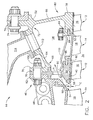
- FIG. 1 shows a prior art compressor assembly 10.
- the compressor assembly 10 includes a number of axially alternating rotor and stator stages 12 and 14.
- Each rotor stage 12 comprises a circumferential array of compressor blades 16 attached to a rotating disk or spool (not shown).
- Each stator stage 14 comprises a circumferential array of stationary stator vanes 18 which are attached to a case assembly 20.
- the case assembly 20 surrounds the rotor stages 12 of the compressor assembly 10.
- the case assembly 20 includes an annular outer case 22 and an annular inner case 24 which are connected together by an annular, radially extending portion 26.
- An annular bleed slot 28 is defined between a rearward-facing wall 30 of the outer case 22 and a forward-facing wall 32 of the inner case 24.
- the bleed slot 28 serves to receive a portion of the compressed air flow from the working gas flowpath 34 and channel it to a plenum 36.
- the inner case 24 has a radially inner flowpath surface 38 which forms the outer boundary of the working gas flowpath 34 and provides a sealing surface for the tips 40 of the compressor blades 16.
- case assembly 20 is designed in a known manner to create uniformly small radial clearance, denoted C in Figure 1, between the tips 40 of the compressor blades 16 and the flowpath surface 38 of the inner case 24.
- the relative size of the radial clearance C is exaggerated for illustration purposes.
- the portion of the inner case 24 that is directly aft of the bleed slot 28 is supported in a cantilevered fashion from the radially extending portion 26 of the case assembly 20.
- the inner case 24 expands more rapidly than the rotor 12, increasing the radial clearance C between the flowpath surface 38 and the tips 40 of the compressor blades 16. This allows backflow of higher-pressure air from downstream of the compressor blades 16, decreasing efficiency and stall margin of the compressor 10.
- FIG. 2 illustrates a compressor assembly 44 that incorporates an exemplary compressor bleed case assembly 46 constructed in accordance with the present invention.
- the basic components of the bleed case assembly 46 are an outer case 48, an inner case 50, and an aft case 52.
- the inner case 50 is axially spaced away from the outer case 48 so that an annular bleed slot 54 is defined between an aft wall 56 of the outer case 48 and a forward wall 58 of a first shroud portion 60 of the inner case 50.
- the outer case 48 is an annular structure, similar to the prior art outer case 22, that surrounds a portion of the compressor stages 12 and forms an attachment point for a plurality of stages 14 of stator vanes 18.
- the outer case 48 differs from the prior art outer case 22 in that is it shorter in the axial direction, having an aft flange 62 that is approximately aligned with the axial position of the bleed slot 54.
- the aft case 52 is an annular component having an axially extending arm 64 and a radially extending arm 66 which are joined to form a generally L-shaped cross section.
- the forward end 68 of the axially extending arm 64 has a first radially extending flange 70 attached thereto, and the aft end 72 of the axially extending arm 64 has a second radially extending flange 74 attached thereto.
- Each of the flanges 70 and 74 includes a plurality of bolt holes 76.
- An annular, axially extending second shroud portion 78 is disposed at the radially inner end 80 of the radially extending arm 66.
- a circumferential mounting groove 82 or other similar structure may be formed in the forward end 84 of the second shroud portion 78 for receiving a mounting rail 86 of an adjacent stator vane 18.
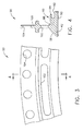
- FIGs 3 and 4 illustrate the inner case 50 in more detail.
- the inner case 50 is an annular component which includes a generally cylindrical first shroud portion 60 having a radially facing outer surface 88 opposite a radially facing inner surface 90.
- the inner case 50 is a continuous circular ring, a small segment of which is shown in Figure 3.
- the inner case 50 could also comprise a plurality of arcuate segments.
- the inner surface 90 of the first shroud portion 50 forms a portion of the outer boundary of the working gas flowpath 34 and provides a sealing surface for the tips 40 of the compressor blades 16.
- a known type of abradable material 42 may be disposed on the inner surface 90.
- a circumferential mounting groove 92 or other similar structure may be formed in the aft end 94 of the first shroud portion 60 for receiving a mounting rail 96 of an adjacent stator vane 18 (see Figure 2).
- a forward wall 58 connects the inner surface 90 and the outer surface 88. The forward wall 58 is disposed at an acute angle to the inner surface 90 so as to define a flow scoop 98.
- a generally planar flange 100 extends radially outwardly from the outer surface 88.
- a circumferential array of bleed openings 102 are formed through the flange 100 radially adjacent the first shroud portion 60.
- a circumferential array of mounting holes 104 are formed through the flange 100 radially outward of the bleed openings 102.
- the bleed case assembly 46 is assembled by placing the flange 100 of the inner case 50 between the aft flange 62 of the outer case 48 and the first flange 70 of the aft case 52.
- the three flanges are secured together with a plurality of fasteners 106 such as the illustrated bolts.
- the flange 100 of the inner case 60 is aligned with the axial position of the blade row immediately aft of the bleed slot 54.
- aligned with the axial position of the blade row it is meant that the axial position of flange 100 falls between the forward and aft edges of the blades 16.
- the flange 100 need not be directly aligned with any particular location along the axial extent of the blades 16, so long as it is placed so that any radial expansion or contraction of the first shroud portion 60 will be transmitted the flange 100 substantially in direct tension or compression.
- the outer, inner and aft cases, along with a row of stator vanes 18, cooperate to define an annular plenum 108.
- An annular seal 110 may be disposed around the stator vane row 14 to prevent leakage between the working gas flowpath 34 and the plenum 108.
- One or more ports 112 are formed in the axial arm 64 of the aft case 52.
- a bleed air manifold 114 may be connected to the ports 112 to receive the bleed air flow from the plenum 114 and duct it to the needed location.
- compressed, heated air flows through the working gas flowpath 34.
- a portion of the flow is diverted into the bleed slot 54, the bleed openings 102, and into the plenum 108, as shown by the arrows labeled A in Figure 2.
- the inner case 50 tends to expand or contract faster than the rotor 12, increasing or decreasing the radial clearance C between the inner surface 90 and the tips 40 of the compressor blades 16, as described above with respect to the prior art compressor case.
- the inner case 50 is mechanically tied to the relative more massive and stable outer case 48 by the flange 100 that extends directly radially outboard of the shroud portion 60.
- This structural arrangement greatly reduces the amount of radial movement of the inner case 50. Because the flange 100 is directly loaded in tension or compression, there is little or no flexing of the shroud portion 60 that would be associated with a cantilevered support. This reduced thermal response decreases the variation of the radial clearance C in changing operating conditions, which improves the efficiency of the compressor and allows closer design tolerances to be implemented.
- a bleed case assembly comprising an annular outer case and an inner case.
- the inner case comprises an annular shroud portion having a radially outer surface opposite a radially inner surface, and a generally planar flange extending radially outwardly from the radially outer surface.
- the flange includes a circumferential array of bleed openings formed therethrough. The flange is attached to the outer case so as to reduce the thermal response of the inner case.
Claims (7)
- Ensemble (44) de compresseur comprenant :un rotor (12) ayant une pluralité d'aubes (16) s'étendant radialement vers l'extérieur fixées à celui-ci ;un carter annulaire extérieur (48) ayant une paroi arrière ; etun carter annulaire intérieur (50) comprenant :caractérisé par une bride (100) qui s'étend radialement vers l'extérieur à partir de ladite surface extérieure, ladite bride étant raccordée audit carter extérieur, alignée sur la position axiale desdites aubes et ayant une pluralité d'ouvertures (102) de purge formées à travers elles.une première partie (60) d'enveloppe entourant lesdites aubes, ladite première partie d'enveloppe ayant une surface intérieure orientée radialement à l'opposé d'une surface extérieure orientée radialement (88), lesdites surfaces intérieure et extérieure étant raccordées par une paroi avant (58) ; et,dans lequel ledit carter intérieur (50) est agencé dans une relation espacée dudit carter extérieur de sorte qu'une fente (54) de purge annulaire soit définie entre ladite paroi arrière (56) dudit carter extérieur et ladite paroi avant (58) de ladite première partie (60) d'enveloppe dudit carter intérieur ;
- Ensemble de compresseur selon la revendication 1 comprenant en outre :une rangée (14) de stator comprenant une pluralité de pales (18) de stator s'étendant radialement vers l'intérieur, chacune desdites pales de stator comprenant une bande annulaire ayant des extrémités avant et arrière (96, 86) ; etun carter arrière annulaire (52) comprenant un bras (64) s'étendant axialement vers l'avant raccordé à un bras (66) s'étendant radialement vers l'intérieur, ledit bras s'étendant radialement vers l'intérieur comprenant une deuxième partie (78) d'enveloppe annulaire dans laquelle ladite rangée de stator est agencée entre ladite première partie (60) d'enveloppe dudit carter intérieur et ladite deuxième partie (78) d'enveloppe dudit carter arrière (52).
- Ensemble de compresseur selon la revendication 2 dans lequel chacune desdites bandes annulaire de la rangée de stator comprend :un rail avant (96) disposé au niveau de ladite extrémité avant de ladite bande annulaire, ledit rail avant étant reçu dans une rainure circonférentielle (92) formée dans ladite première partie (60) d'enveloppe ; et,un rail arrière (86) disposé au niveau de l'extrémité arrière de ladite bande annulaire, ledit rail arrière étant reçu dans une rainure circonférentielle (82) formée dans ladite deuxième partie (78) d'enveloppe.
- Ensemble de compresseur selon la revendication 1, comprenant en outre un joint annulaire (110) disposé autour de ladite rangée de stator.
- Ensemble annulaire selon la revendication 1, comprenant en outre un matériau abrasable disposé sur ladite surface radialement intérieure de ladite première partie d'enveloppe.
- Ensemble de compresseur selon la revendication 1 dans lequel ladite paroi avant (58) est disposée à un angle aigu de ladite surface intérieure.
- Ensemble de compresseur selon la revendication 1 dans lequel la bride comprend en outre un réseau circonférentiel de trous (104) de montage formés à travers celui-ci, radialement extérieur desdites ouvertures de purge.
Applications Claiming Priority (2)
| Application Number | Priority Date | Filing Date | Title |
|---|---|---|---|
| US219961 | 1994-03-30 | ||
| US10/219,961 US6783324B2 (en) | 2002-08-15 | 2002-08-15 | Compressor bleed case |
Publications (3)
| Publication Number | Publication Date |
|---|---|
| EP1398474A2 EP1398474A2 (fr) | 2004-03-17 |
| EP1398474A3 EP1398474A3 (fr) | 2005-01-26 |
| EP1398474B1 true EP1398474B1 (fr) | 2008-01-23 |
Family
ID=31714836
Family Applications (1)
| Application Number | Title | Priority Date | Filing Date |
|---|---|---|---|
| EP03253582A Expired - Fee Related EP1398474B1 (fr) | 2002-08-15 | 2003-06-06 | Bôitier de soutirage d'un compresseur |
Country Status (5)
| Country | Link |
|---|---|
| US (1) | US6783324B2 (fr) |
| EP (1) | EP1398474B1 (fr) |
| JP (1) | JP4393797B2 (fr) |
| DE (1) | DE60318792T2 (fr) |
| ES (1) | ES2300544T3 (fr) |
Families Citing this family (42)
| Publication number | Priority date | Publication date | Assignee | Title |
|---|---|---|---|---|
| US7094029B2 (en) * | 2003-05-06 | 2006-08-22 | General Electric Company | Methods and apparatus for controlling gas turbine engine rotor tip clearances |
| FR2860041B1 (fr) * | 2003-09-22 | 2005-11-25 | Snecma Moteurs | Realisation de l'etancheite dans un turboreacteur pour le prelevement cabine par tube a double rotule |
| FR2875851B1 (fr) * | 2004-09-28 | 2006-12-29 | Snecma Moteurs Sa | Dispositif d'etancheite dispose entre un compresseur haute-pression et un diffuseur de turbomachine |
| FR2878293B1 (fr) * | 2004-11-24 | 2009-08-21 | Snecma Moteurs Sa | Montage de secteurs de distributeur dans un compresseur axial |
| WO2006091138A1 (fr) * | 2005-02-25 | 2006-08-31 | Volvo Aero Corporation | Structure de purge pour passage de purge dans un moteur a turbine a gaz |
| US7374396B2 (en) * | 2005-02-28 | 2008-05-20 | General Electric Company | Bolt-on radial bleed manifold |
| US7704038B2 (en) * | 2006-11-28 | 2010-04-27 | General Electric Company | Method and apparatus to facilitate reducing losses in turbine engines |
| US8388308B2 (en) * | 2007-10-30 | 2013-03-05 | General Electric Company | Asymmetric flow extraction system |
| FR2925130B1 (fr) * | 2007-12-14 | 2012-07-27 | Snecma | Dispositif de prelevement d'air dans un compresseur de turbomachine |
| FR2925109B1 (fr) * | 2007-12-14 | 2015-05-15 | Snecma | Module de turbomachine muni d'un dispositif d'amelioration des jeux radiaux |
| EP2078837A1 (fr) * | 2008-01-11 | 2009-07-15 | Siemens Aktiengesellschaft | Dispositif de prélèvement d'air pour un compresseur d'un moteur à turbine à gaz |
| US8100633B2 (en) * | 2008-03-11 | 2012-01-24 | United Technologies Corp. | Cooling air manifold splash plates and gas turbines engine systems involving such splash plates |
| DE102010036071A1 (de) * | 2010-09-01 | 2012-03-01 | Mtu Aero Engines Gmbh | Gehäuseseitige Struktur einer Turbomaschine |
| US8734091B2 (en) * | 2011-04-27 | 2014-05-27 | General Electric Company | Axial compressor with arrangement for bleeding air from variable stator vane stages |
| FR2978732B1 (fr) * | 2011-08-05 | 2013-09-06 | Airbus Operations Sas | Dispositif de liaison plus particulierement adapte pour assurer la liaison entre une entree d'air et une motorisation d'une nacelle d'aeronef |
| FR2978735A1 (fr) * | 2011-08-05 | 2013-02-08 | Airbus Operations Sas | Dispositif de liaison plus particulierement adapte pour assurer la liaison entre une entree d'air et une motorisation d'une nacelle d'aeronef |
| US9322337B2 (en) * | 2012-06-20 | 2016-04-26 | United Technologies Corporation | Aerodynamic intercompressor bleed ports |
| US9528391B2 (en) * | 2012-07-17 | 2016-12-27 | United Technologies Corporation | Gas turbine engine outer case with contoured bleed boss |
| WO2014098936A1 (fr) | 2012-12-18 | 2014-06-26 | United Technologies Corporation | Carter interne de moteur à turbine à gaz comprenant des fentes de purge non symétriques |
| JP6092613B2 (ja) | 2012-12-26 | 2017-03-08 | 三菱日立パワーシステムズ株式会社 | 軸流圧縮機及び軸流圧縮機の運転方法 |
| US9845695B2 (en) | 2012-12-29 | 2017-12-19 | United Technologies Corporation | Gas turbine seal assembly and seal support |
| WO2014105803A1 (fr) | 2012-12-29 | 2014-07-03 | United Technologies Corporation | Ensemble de joint d'étanchéité de turbine à gaz et support de joint d'étanchéité |
| US9810157B2 (en) | 2013-03-04 | 2017-11-07 | Pratt & Whitney Canada Corp. | Compressor shroud reverse bleed holes |
| US9726084B2 (en) | 2013-03-14 | 2017-08-08 | Pratt & Whitney Canada Corp. | Compressor bleed self-recirculating system |
| EP2803822B1 (fr) * | 2013-05-13 | 2019-12-04 | Safran Aero Boosters SA | Système de prélèvement d'air de turbomachine axiale |
| US10184354B2 (en) * | 2013-06-19 | 2019-01-22 | United Technologies Corporation | Windback heat shield |
| DE102013017713B4 (de) * | 2013-10-24 | 2022-10-27 | Man Energy Solutions Se | Turbomaschine |
| EP2871368B1 (fr) | 2013-11-12 | 2018-09-12 | MTU Aero Engines GmbH | Compresseur de turbine à gaz |
| EP2977590B1 (fr) * | 2014-07-25 | 2018-01-31 | Ansaldo Energia Switzerland AG | Ensemble compresseur pour turbine à gaz |
| GB201518448D0 (en) * | 2015-10-19 | 2015-12-02 | Rolls Royce | Compressor |
| JP6563312B2 (ja) * | 2015-11-05 | 2019-08-21 | 川崎重工業株式会社 | ガスタービンエンジンの抽気構造 |
| FR3048017B1 (fr) * | 2016-02-24 | 2019-05-31 | Safran Aircraft Engines | Redresseur pour compresseur de turbomachine d'aeronef, comprenant des orifices de prelevement d'air de forme etiree selon la direction circonferentielle |
| US10302019B2 (en) | 2016-03-03 | 2019-05-28 | General Electric Company | High pressure compressor augmented bleed with autonomously actuated valve |
| US10227930B2 (en) | 2016-03-28 | 2019-03-12 | General Electric Company | Compressor bleed systems in turbomachines and methods of extracting compressor airflow |
| US10539153B2 (en) | 2017-03-14 | 2020-01-21 | General Electric Company | Clipped heat shield assembly |
| EP3385506B1 (fr) * | 2017-04-07 | 2019-10-30 | MTU Aero Engines GmbH | Agencement d'étanchéité pour turbine à gaz |
| US20180313364A1 (en) * | 2017-04-27 | 2018-11-01 | General Electric Company | Compressor apparatus with bleed slot including turning vanes |
| US10934943B2 (en) * | 2017-04-27 | 2021-03-02 | General Electric Company | Compressor apparatus with bleed slot and supplemental flange |
| EP4108884A4 (fr) * | 2020-02-20 | 2023-11-29 | Kawasaki Jukogyo Kabushiki Kaisha | Structure d'assemblage pour compresseur de moteur à turbine à gaz |
| FR3109792B1 (fr) * | 2020-04-30 | 2022-04-29 | Safran Aircraft Engines | Montage d’un anneau d’étanchéité sur une turbomachine aéronautique |
| US20230003141A1 (en) * | 2021-06-30 | 2023-01-05 | Pratt & Whitney Canada Corp. | Outside fit flange for aircraft engine |
| US11828226B2 (en) * | 2022-04-13 | 2023-11-28 | General Electric Company | Compressor bleed air channels having a pattern of vortex generators |
Family Cites Families (23)
| Publication number | Priority date | Publication date | Assignee | Title |
|---|---|---|---|---|
| US593277A (en) * | 1897-11-09 | Herbert l | ||
| BE463344A (fr) * | 1945-01-23 | |||
| BE551816A (fr) * | 1955-11-10 | |||
| US3142438A (en) * | 1961-04-21 | 1964-07-28 | Rolls Royce | Multi-stage axial compressor |
| US3945759A (en) * | 1974-10-29 | 1976-03-23 | General Electric Company | Bleed air manifold |
| US3966354A (en) * | 1974-12-19 | 1976-06-29 | General Electric Company | Thermal actuated valve for clearance control |
| GB1501916A (en) | 1975-06-20 | 1978-02-22 | Rolls Royce | Matching thermal expansions of components of turbo-machines |
| DE3316535A1 (de) * | 1983-05-06 | 1984-11-08 | MTU Motoren- und Turbinen-Union München GmbH, 8000 München | Turboverdichter mit einlaufbelag |
| JPS62153504A (ja) * | 1985-12-26 | 1987-07-08 | Toshiba Corp | シユラウドセグメント |
| GB2192229B (en) | 1986-07-04 | 1990-05-02 | Rolls Royce Plc | A compressor and air bleed system |
| US5059093A (en) | 1990-06-07 | 1991-10-22 | United Technologies Corporation | Compressor bleed port |
| US5203162A (en) | 1990-09-12 | 1993-04-20 | United Technologies Corporation | Compressor bleed manifold for a gas turbine engine |
| US5118253A (en) | 1990-09-12 | 1992-06-02 | United Technologies Corporation | Compressor case construction with backbone |
| US5209633A (en) | 1990-11-19 | 1993-05-11 | General Electric Company | High pressure compressor flowpath bleed valve extraction slot |
| US5181826A (en) * | 1990-11-23 | 1993-01-26 | General Electric Company | Attenuating shroud support |
| US5351478A (en) | 1992-05-29 | 1994-10-04 | General Electric Company | Compressor casing assembly |
| US5327716A (en) | 1992-06-10 | 1994-07-12 | General Electric Company | System and method for tailoring rotor tip bleed air |
| US5593276A (en) * | 1995-06-06 | 1997-01-14 | General Electric Company | Turbine shroud hanger |
| US5593277A (en) * | 1995-06-06 | 1997-01-14 | General Electric Company | Smart turbine shroud |
| FR2780443B1 (fr) * | 1998-06-25 | 2000-08-04 | Snecma | Anneau de stator de turbine haute pression d'une turbomachine |
| US6109868A (en) | 1998-12-07 | 2000-08-29 | General Electric Company | Reduced-length high flow interstage air extraction |
| DE19919654A1 (de) * | 1999-04-29 | 2000-11-02 | Abb Alstom Power Ch Ag | Hitzeschild für eine Gasturbine |
| US6325595B1 (en) | 2000-03-24 | 2001-12-04 | General Electric Company | High recovery multi-use bleed |
-
2002
- 2002-08-15 US US10/219,961 patent/US6783324B2/en not_active Expired - Lifetime
-
2003
- 2003-06-06 EP EP03253582A patent/EP1398474B1/fr not_active Expired - Fee Related
- 2003-06-06 ES ES03253582T patent/ES2300544T3/es not_active Expired - Lifetime
- 2003-06-06 DE DE60318792T patent/DE60318792T2/de not_active Expired - Lifetime
- 2003-06-13 JP JP2003168571A patent/JP4393797B2/ja not_active Expired - Fee Related
Also Published As
| Publication number | Publication date |
|---|---|
| EP1398474A2 (fr) | 2004-03-17 |
| EP1398474A3 (fr) | 2005-01-26 |
| DE60318792D1 (de) | 2008-03-13 |
| JP4393797B2 (ja) | 2010-01-06 |
| DE60318792T2 (de) | 2009-01-22 |
| ES2300544T3 (es) | 2008-06-16 |
| US6783324B2 (en) | 2004-08-31 |
| US20040033133A1 (en) | 2004-02-19 |
| JP2004076726A (ja) | 2004-03-11 |
Similar Documents
| Publication | Publication Date | Title |
|---|---|---|
| EP1398474B1 (fr) | Bôitier de soutirage d'un compresseur | |
| US6290459B1 (en) | Stationary flowpath components for gas turbine engines | |
| US5215435A (en) | Angled cooling air bypass slots in honeycomb seals | |
| EP0578460B1 (fr) | Turbine à gaz | |
| EP1211386B1 (fr) | Anneau d'étanchéité pour turbines et turbine associée | |
| EP1780380B1 (fr) | Joint d'étanchéité de turbine à gaz entre les aubes mobiles et statoriques | |
| US5211533A (en) | Flow diverter for turbomachinery seals | |
| US4425079A (en) | Air sealing for turbomachines | |
| US11293304B2 (en) | Gas turbine engines including channel-cooled hooks for retaining a part relative to an engine casing structure | |
| US6935836B2 (en) | Compressor casing with passive tip clearance control and endwall ovalization control | |
| CA2712113C (fr) | Scellement et refroidissement au joint entre les segments annulaires d'enveloppe de turbine | |
| US8177492B2 (en) | Passage obstruction for improved inlet coolant filling | |
| EP2952689B1 (fr) | Espaceur de joint de bordure segmentée pour un moteur à turbine à gaz | |
| EP0578461A1 (fr) | Support de tuyère de turbine | |
| GB2033020A (en) | Gas turbine working fluid seal | |
| US4747750A (en) | Transition duct seal | |
| WO2014081517A1 (fr) | Agencement de montage et d'étanchéité de carénage de turbine | |
| EP3090140B1 (fr) | Joint à air extérieur de pale avec jointement d'air secondaire | |
| EP0877149A2 (fr) | Refroidissement du carter d'une turbine à gaz | |
| US20180142564A1 (en) | Combined turbine nozzle and shroud deflection limiter | |
| EP2447475B1 (fr) | Agencement de fixation d'une aube | |
| US10815884B2 (en) | Gas turbine engine de-icing system | |
| US10753222B2 (en) | Gas turbine engine blade outer air seal | |
| US6129513A (en) | Fluid seal | |
| US10746033B2 (en) | Gas turbine engine component |
Legal Events
| Date | Code | Title | Description |
|---|---|---|---|
| PUAI | Public reference made under article 153(3) epc to a published international application that has entered the european phase |
Free format text: ORIGINAL CODE: 0009012 |
|
| AK | Designated contracting states |
Kind code of ref document: A2 Designated state(s): AT BE BG CH CY CZ DE DK EE ES FI FR GB GR HU IE IT LI LU MC NL PT RO SE SI SK TR |
|
| AX | Request for extension of the european patent |
Extension state: AL LT LV MK |
|
| PUAL | Search report despatched |
Free format text: ORIGINAL CODE: 0009013 |
|
| AK | Designated contracting states |
Kind code of ref document: A3 Designated state(s): AT BE BG CH CY CZ DE DK EE ES FI FR GB GR HU IE IT LI LU MC NL PT RO SE SI SK TR |
|
| AX | Request for extension of the european patent |
Extension state: AL LT LV MK |
|
| 17P | Request for examination filed |
Effective date: 20050726 |
|
| AKX | Designation fees paid |
Designated state(s): DE ES FR GB IT SE |
|
| 17Q | First examination report despatched |
Effective date: 20051103 |
|
| GRAP | Despatch of communication of intention to grant a patent |
Free format text: ORIGINAL CODE: EPIDOSNIGR1 |
|
| GRAS | Grant fee paid |
Free format text: ORIGINAL CODE: EPIDOSNIGR3 |
|
| GRAA | (expected) grant |
Free format text: ORIGINAL CODE: 0009210 |
|
| AK | Designated contracting states |
Kind code of ref document: B1 Designated state(s): DE ES FR GB IT SE |
|
| REG | Reference to a national code |
Ref country code: GB Ref legal event code: FG4D |
|
| REF | Corresponds to: |
Ref document number: 60318792 Country of ref document: DE Date of ref document: 20080313 Kind code of ref document: P |
|
| REG | Reference to a national code |
Ref country code: SE Ref legal event code: TRGR |
|
| REG | Reference to a national code |
Ref country code: ES Ref legal event code: FG2A Ref document number: 2300544 Country of ref document: ES Kind code of ref document: T3 |
|
| PLBE | No opposition filed within time limit |
Free format text: ORIGINAL CODE: 0009261 |
|
| STAA | Information on the status of an ep patent application or granted ep patent |
Free format text: STATUS: NO OPPOSITION FILED WITHIN TIME LIMIT |
|
| 26N | No opposition filed |
Effective date: 20081024 |
|
| REG | Reference to a national code |
Ref country code: FR Ref legal event code: PLFP Year of fee payment: 14 |
|
| REG | Reference to a national code |
Ref country code: FR Ref legal event code: PLFP Year of fee payment: 15 |
|
| PGFP | Annual fee paid to national office [announced via postgrant information from national office to epo] |
Ref country code: GB Payment date: 20170627 Year of fee payment: 15 Ref country code: FR Payment date: 20170627 Year of fee payment: 15 |
|
| PGFP | Annual fee paid to national office [announced via postgrant information from national office to epo] |
Ref country code: SE Payment date: 20170628 Year of fee payment: 15 Ref country code: IT Payment date: 20170622 Year of fee payment: 15 |
|
| PGFP | Annual fee paid to national office [announced via postgrant information from national office to epo] |
Ref country code: DE Payment date: 20170628 Year of fee payment: 15 Ref country code: ES Payment date: 20170705 Year of fee payment: 15 |
|
| REG | Reference to a national code |
Ref country code: DE Ref legal event code: R119 Ref document number: 60318792 Country of ref document: DE |
|
| REG | Reference to a national code |
Ref country code: SE Ref legal event code: EUG |
|
| PG25 | Lapsed in a contracting state [announced via postgrant information from national office to epo] |
Ref country code: SE Free format text: LAPSE BECAUSE OF NON-PAYMENT OF DUE FEES Effective date: 20180607 |
|
| GBPC | Gb: european patent ceased through non-payment of renewal fee |
Effective date: 20180606 |
|
| PG25 | Lapsed in a contracting state [announced via postgrant information from national office to epo] |
Ref country code: GB Free format text: LAPSE BECAUSE OF NON-PAYMENT OF DUE FEES Effective date: 20180606 Ref country code: DE Free format text: LAPSE BECAUSE OF NON-PAYMENT OF DUE FEES Effective date: 20190101 Ref country code: IT Free format text: LAPSE BECAUSE OF NON-PAYMENT OF DUE FEES Effective date: 20180606 Ref country code: FR Free format text: LAPSE BECAUSE OF NON-PAYMENT OF DUE FEES Effective date: 20180630 |
|
| REG | Reference to a national code |
Ref country code: ES Ref legal event code: FD2A Effective date: 20190916 |
|
| PG25 | Lapsed in a contracting state [announced via postgrant information from national office to epo] |
Ref country code: ES Free format text: LAPSE BECAUSE OF NON-PAYMENT OF DUE FEES Effective date: 20180607 |