EP1210220B1 - Verfahren zum führen einer materialbahn - Google Patents
Verfahren zum führen einer materialbahn Download PDFInfo
- Publication number
- EP1210220B1 EP1210220B1 EP00949476A EP00949476A EP1210220B1 EP 1210220 B1 EP1210220 B1 EP 1210220B1 EP 00949476 A EP00949476 A EP 00949476A EP 00949476 A EP00949476 A EP 00949476A EP 1210220 B1 EP1210220 B1 EP 1210220B1
- Authority
- EP
- European Patent Office
- Prior art keywords
- material web
- web
- spreader roller
- spreader
- roller
- Prior art date
- Legal status (The legal status is an assumption and is not a legal conclusion. Google has not performed a legal analysis and makes no representation as to the accuracy of the status listed.)
- Expired - Lifetime
Links
- 239000000463 material Substances 0.000 title claims abstract description 89
- 238000000034 method Methods 0.000 title claims abstract description 38
- 230000002093 peripheral effect Effects 0.000 claims abstract description 17
- 230000001276 controlling effect Effects 0.000 claims description 5
- 229920001169 thermoplastic Polymers 0.000 claims description 5
- -1 polyethylene Polymers 0.000 claims description 4
- 238000003892 spreading Methods 0.000 claims description 4
- 230000001105 regulatory effect Effects 0.000 claims description 3
- 239000004698 Polyethylene Substances 0.000 claims description 2
- 239000004743 Polypropylene Substances 0.000 claims description 2
- 239000004417 polycarbonate Substances 0.000 claims description 2
- 229920000515 polycarbonate Polymers 0.000 claims description 2
- 229920000728 polyester Polymers 0.000 claims description 2
- 229920000573 polyethylene Polymers 0.000 claims description 2
- 229920001155 polypropylene Polymers 0.000 claims description 2
- 239000004416 thermosoftening plastic Substances 0.000 claims description 2
- 229920000089 Cyclic olefin copolymer Polymers 0.000 claims 1
- 238000004519 manufacturing process Methods 0.000 description 8
- 230000037303 wrinkles Effects 0.000 description 6
- 238000007654 immersion Methods 0.000 description 4
- 238000005259 measurement Methods 0.000 description 2
- 239000007921 spray Substances 0.000 description 2
- 238000004804 winding Methods 0.000 description 2
- 240000005561 Musa balbisiana Species 0.000 description 1
- 235000018290 Musa x paradisiaca Nutrition 0.000 description 1
- 239000004952 Polyamide Substances 0.000 description 1
- 230000009286 beneficial effect Effects 0.000 description 1
- 230000005540 biological transmission Effects 0.000 description 1
- 239000002131 composite material Substances 0.000 description 1
- 239000011243 crosslinked material Substances 0.000 description 1
- 150000001925 cycloalkenes Chemical class 0.000 description 1
- 230000003247 decreasing effect Effects 0.000 description 1
- 230000001419 dependent effect Effects 0.000 description 1
- 230000010339 dilation Effects 0.000 description 1
- 239000013013 elastic material Substances 0.000 description 1
- 239000004744 fabric Substances 0.000 description 1
- 239000011888 foil Substances 0.000 description 1
- 238000012423 maintenance Methods 0.000 description 1
- 238000011089 mechanical engineering Methods 0.000 description 1
- 239000002184 metal Substances 0.000 description 1
- 239000000123 paper Substances 0.000 description 1
- 239000004033 plastic Substances 0.000 description 1
- 229920003023 plastic Polymers 0.000 description 1
- 239000002985 plastic film Substances 0.000 description 1
- 229920002647 polyamide Polymers 0.000 description 1
- 229920000098 polyolefin Polymers 0.000 description 1
- 238000003825 pressing Methods 0.000 description 1
- 238000003672 processing method Methods 0.000 description 1
- 238000005096 rolling process Methods 0.000 description 1
- 230000003068 static effect Effects 0.000 description 1
- 238000004381 surface treatment Methods 0.000 description 1
- 239000012815 thermoplastic material Substances 0.000 description 1
Images


Classifications
-
- B—PERFORMING OPERATIONS; TRANSPORTING
- B65—CONVEYING; PACKING; STORING; HANDLING THIN OR FILAMENTARY MATERIAL
- B65H—HANDLING THIN OR FILAMENTARY MATERIAL, e.g. SHEETS, WEBS, CABLES
- B65H23/00—Registering, tensioning, smoothing or guiding webs
- B65H23/02—Registering, tensioning, smoothing or guiding webs transversely
- B65H23/022—Registering, tensioning, smoothing or guiding webs transversely by tentering devices
- B65H23/025—Registering, tensioning, smoothing or guiding webs transversely by tentering devices by rollers
-
- B—PERFORMING OPERATIONS; TRANSPORTING
- B65—CONVEYING; PACKING; STORING; HANDLING THIN OR FILAMENTARY MATERIAL
- B65H—HANDLING THIN OR FILAMENTARY MATERIAL, e.g. SHEETS, WEBS, CABLES
- B65H2301/00—Handling processes for sheets or webs
- B65H2301/50—Auxiliary process performed during handling process
- B65H2301/51—Modifying a characteristic of handled material
- B65H2301/512—Changing form of handled material
- B65H2301/5124—Stretching; Tentering
- B65H2301/51242—Stretching transversely; Tentering
- B65H2301/512422—Stretching transversely; Tentering involving roller pair acting on edge of web
-
- B—PERFORMING OPERATIONS; TRANSPORTING
- B65—CONVEYING; PACKING; STORING; HANDLING THIN OR FILAMENTARY MATERIAL
- B65H—HANDLING THIN OR FILAMENTARY MATERIAL, e.g. SHEETS, WEBS, CABLES
- B65H2404/00—Parts for transporting or guiding the handled material
- B65H2404/10—Rollers
- B65H2404/13—Details of longitudinal profile
- B65H2404/131—Details of longitudinal profile shape
- B65H2404/1314—Details of longitudinal profile shape convex
-
- B—PERFORMING OPERATIONS; TRANSPORTING
- B65—CONVEYING; PACKING; STORING; HANDLING THIN OR FILAMENTARY MATERIAL
- B65H—HANDLING THIN OR FILAMENTARY MATERIAL, e.g. SHEETS, WEBS, CABLES
- B65H2511/00—Dimensions; Position; Numbers; Identification; Occurrences
- B65H2511/20—Location in space
- B65H2511/21—Angle
- B65H2511/216—Orientation, e.g. with respect to direction of movement
-
- B—PERFORMING OPERATIONS; TRANSPORTING
- B65—CONVEYING; PACKING; STORING; HANDLING THIN OR FILAMENTARY MATERIAL
- B65H—HANDLING THIN OR FILAMENTARY MATERIAL, e.g. SHEETS, WEBS, CABLES
- B65H2513/00—Dynamic entities; Timing aspects
- B65H2513/10—Speed
-
- B—PERFORMING OPERATIONS; TRANSPORTING
- B65—CONVEYING; PACKING; STORING; HANDLING THIN OR FILAMENTARY MATERIAL
- B65H—HANDLING THIN OR FILAMENTARY MATERIAL, e.g. SHEETS, WEBS, CABLES
- B65H2515/00—Physical entities not provided for in groups B65H2511/00 or B65H2513/00
- B65H2515/30—Forces; Stresses
- B65H2515/31—Tensile forces
Definitions
- the present invention relates to a method for guiding a material web (1) which is guided and transported between rotating rollers. becomes.
- the US 22 89 196 describes the so-called banana roll. These cylindrical roller is at least on the surface of a rubber-elastic Material and specially shaped. The roller is over her entire Length bent and pressed against the running web. The shape the roller causes when pressing the roller in running web a Breitiens in the transverse direction. The thereby generated power transmission of lateral forces and the achievable transverse movement but is extremely low and therefore useless for many applications.
- EP 0 009 294 a method for drawing a web of material is disclosed described from a crosslinked material. After the process, the material web seized and guided by the side of the sling, which is the desired Wide reach. The clips are controlled so that the web is stretched to a predetermined width. In case of deviations from the given width, the angles of the clips are adjusted.
- the present invention is based on the object, a method and a device for spreading a sheet-like material web (1), the be guided over rollers and transported to provide.
- the procedure should ensure that the material web (1) without wrinkles and free from distortion can be guided and transported in the longitudinal and transverse directions.
- the method can be adapted i.e. the method should at different speeds of the web (1), as well as successfully used for different materials become.
- the device should be low maintenance and less susceptible to repair be.
- the longitudinal direction in the sense of the present invention is the direction in which the material web (1) is running; this direction is also called machine direction designated.
- the transverse direction is the one in the sense of the present invention Direction that is at an angle of 90 °, i. transverse to the machine direction runs.
- the method according to the invention eliminates the disadvantages caused by the in Longitudinally introduced tensile stress arise.
- the procedure is for different sheet-like material webs suitable and can be advantageous everywhere be used, where there are wrinkles and / or distortions in the longitudinal direction of the material web when passing over and between rotating Rolling comes.
- the method has been particularly suitable for films made of plastics, especially made of thermoplastic materials, proven. Slides off Thermoplastic plastics are, for example, films of polyester and Polyolefins, such as polyethylenes, polypropylenes, cycloolefins, polycarbonate, Polyamides etc. Such films can be constructed as single-layered or multilayered be.
- the process can also be used for webs of other materials be applied, such as fabric, paper or metal webs. Likewise, the process is beneficial when it comes to the production of laminates goes or while guiding the laminate itself. Also for the laminates are different materials possible. The method is especially for webs with a thickness of 0.5 to 500 ⁇ m, preferably 2 to 200 ⁇ m, suitable.
- the web speed v F of the web is determined by the desired rate of production or processing. Usual web speeds are depending on the type of material between 1 to 2500 m / min, preferably 5 to 1000 m / min. For films of thermoplastic polymers speeds of 100 to 1000 m / min are common.
- the tension in the longitudinal direction to be introduced into the material web depends on the one hand on the material properties (eg type of material) and their thickness or the purpose of the following devices (eg thickness measurement, surface treatment, Wikkelstation), which are integrated or connected in the roller assembly, and on the other hang the Web speed v F itself and the applied tension in the running direction from each other.
- the process according to the invention is particularly advantageous for high-speed productions or processing.
- the material web (1) is inventively guided in its edge region over one or more spreader rollers (2).
- the edge region of a material web (1) is generally narrow in relation to the total width of the web. The exact width of such an edge region will depend on the nature of the material and the overall width of the web. In general, an edge region is understood to be the outer regions of the web, which together can make up to 30% of the total width. In general, each edge region is in each case 1 to 10% of the total width of the material web. It goes without saying that each endless web of material has two edges which run parallel to the running direction. The following information about "the edge area" of course apply in the same way for the opposite edge.
- the material web (1) is guided in the edge region via a spreader roll (2).
- This spreader roller (2) is dimensioned so that its diameter is generally greater than its width b g , so that the term “role” more aptly characterizes the element than the term “roller”.
- appropriately sized rollers can fulfill an equivalent purpose.
- the person skilled in the art will select the size of the element as a function of the material web (1), the web speed and the width of the edge region.
- the spreader roller (2) has a width b g of 1 to 500 mm, preferably 1 to 150 mm, in particular 1 to 50 mm.
- the diameter of the Breithaltrolle (2) is generally 1 to 10% of the web width (1).
- the material web width depends on the type of material and the given machine dimensions and can therefore vary within a wide range.
- films made of thermoplastics are conventional web widths in the production of the film before cross-stretching between 0.2 to 2 m, preferably 0.5 to 1 m, but after the transverse stretching at 0.5 to 30 m, preferably 1 to 20 m. Accordingly, the absolute values of the roll diameter can vary within wide limits.
- the spreader roller (2) can in principle be made of any material or composite material be manufactured that meets the requirements.
- the surface should be designed so that a positive connection between the material web (1) and the roller surface (5) is conveyed. In a special Embodiment, it is necessary to apply the surface to electrical Zero potential.
- the roll is bevelled or rounded at the edges so that the lateral surface b M narrow, so that the contact surface (3) between the material web (1) and the roller surface (5) ideally to a point or on a line is reduced.
- the lateral surface b M for bevelled or rounded embodiments will have a width of 0 to 400 mm, preferably 1 to 200 mm.
- Such chamfered or rounded rollers are particularly advantageous since the relative movement between lateral surface b M and material web (1) is always lower with decreasing lateral surface.
- beveled or rounded rollers provide some protection against damage to the web (1).
- the spreader roller (2) does not necessarily need an independent drive. It can be driven via the moving material web (1) and then has a peripheral speed v R which corresponds to the web speed v F of the material web (1) taking into account the angle of attack ⁇ .
- the spreader roller (2) is provided with a drive, by means of which the peripheral speed of the roller V R can be controlled or regulated. Such driven Breithalterollen are preferred.
- the drive makes it possible to control or regulate the peripheral speed of the roller and also to control the transversely generated tension.
- the peripheral speed v R is adjusted so that the peripheral speed v R is at least as great, preferably greater than the web speed v F of the material web (1).
- the lead of the peripheral speed v R of the roller is generally adjusted so that there is no relative movement between the roller surface (5) and the material web (1).
- the spreader roller (2) has a electrically conductive surface, which switched to a zero electrical potential is.
- This surface allows a particularly advantageous embodiment the inventive method in which a non-positive Connection between the contact surface of the spreader roller (2) and the Material web (1) by an electrostatic charge of the material web (1) is achieved. This embodiment of the method will be detailed below explained.
- the spreader rollers (2) are positioned in the two edge regions of the material web (1).
- the positioning of the spreader rollers (2) on the moving material web (1) is chosen from a mechanical engineering and ergonomic point of view.
- Powered Breithalterollen (2) are driven so that they rotate in the running direction of the web (1).
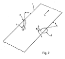
- an angle of attack ⁇ is set (see Fig. 7). This angle must be> 0 ° and ⁇ 90 °. In general, one will set an angle of attack in the range of 2 to 50 °, preferably 5 to 30 °.
- the roller speed v R is controlled or regulated.
- the role must be as far as the Material web (1) are brought, that the roller surface (5) in the web (1) dips. This positioning is below also as immersion depth h (see Fig. 6). About the immersion depths of the spreader roller (2) in the moving web (1) is determined how far the web (1) wraps around the spreader roll (2). The higher the wrap angle ⁇ the more contact surface (3) arises between the roller surface (5) and the material web (1).
- the non-positive winding of the role by an electrostatic charge the material web (1) supported in a further, particularly advantageous embodiment of the invention.
- a spray electrode (4) attached (see Fig. 6 and 7).
- this spray electrode (4) is in a small area, an electric Charge applied to the web (1). Does the material web loaded in this way run? (1) then via an electrically conductive and at electrical zero potential switched Breithalterolle (2), the web (1) of the Surface of the spreader roller (5) tightened. This leads to a special good, non-positive connection between the material web (1) and the Contact surface (3), possibly also to a larger wrap angle ⁇ .
- the invention provides a simple way of tension in the transverse direction to bring in a running material web. This procedure is special advantageous because it offers different possibilities, this tension to control in the transverse direction.
- the tension can be controlled by controlling the Roll diameter, by the angle of attack ⁇ , by the immersion depth h, by the configuration of the roller surface, by the peripheral speed, by the positioning of the spreader roll to the web through which static charge can be controlled. This is a very fine dosage of acting in the transverse direction forces on various specifications possible.
- the inventive method is extremely flexible and for a variety of Materials and production or processing methods advantageously used. It allows webs to be wrinkle free between rotating rollers lead and build a controlled tension in the transverse direction, so that dislocations or other disturbances caused by tensions in Longitudinal, can be safely avoided.
Landscapes
- Registering, Tensioning, Guiding Webs, And Rollers Therefor (AREA)
- Replacement Of Web Rolls (AREA)
- Train Traffic Observation, Control, And Security (AREA)
- Hydraulic Turbines (AREA)
- Transplanting Machines (AREA)
Description
Die Materialbahn (1) wird erfindungsgemäß in ihrem Randbereich über eine oder mehrere Breithalterollen (2) geführt. Der Randbereich einer Materialbahn (1) ist in der Regel schmal im Verhältnis zur Gesamtbreite der Bahn. Die genaue Breite eines solchen Randbereichs wird von der Art des Materials und der Gesamtbreite der Bahn abhängen. Im allgemeinen versteht man unter einem Randbereich die äußeren Bereiche der Bahn, welche zusammen bis zu 30% der Gesamtbreite ausmachen können. Im allgemeinen beträgt jeder Randbereich jeweils 1 bis 10% der Gesamtbreite der Materialbahn. Es versteht sich von selbst, daß jede endlose Materialbahn zwei Ränder hat, die parallel zur Laufrichtung verlaufen. Nachstehende Angaben über "den Randbereich" gelten selbstverständlich in gleicher Weise auch für den jeweils gegenüberliegenden Rand.
Claims (12)
- Verfahren zum Breithalten beim Führen einer flächenförmigen Materialbahn (1), bei welchem die Materialbahn (1) in einer Anordnung von rotierende Walzen mit einer Bahngeschwindigkeit vF läuft, die Materialbahn (1) in ihrem Randbereich über eine Breithalterolle (2) geführt wird, welche eine Zugspannung in Querrichtung, d.h. quer zur Laufrichtung der Materialbahn (1) erzeugt, dadurch gekennzeichnet, daß diese Spannung in Querrichtung durch Regelung der Umfangsgeschwindigkeit vR der Breithatterolle (2) und durch Steuerung des Anstellwinkels α und des Umschlingungswinkels β gesteuert wird und wobei die Umfangsgeschwindigkeit vR > Bahngeschwindigkeit vF ist.
- Verfahren nach Anspruch 1 dadurch gekennzeichnet, daß die Materialbahn (1) eine Materialbahn aus einem thermoplastischen Kunststoff, vorzugsweise Polyester, Polyethylen, Polycarbonat, Polypropylen oder ein Cycloolefinpolymer ist.
- Verfahren nach Anspruch 1 und/oder 2 dadurch gekennzeichnet, daß die Materialbahn (1) eine Dicke von 0,5 bis 500 µm, vorzugsweise 2 bis 200µm hat.
- Verfahren nach einem oder mehreren der Ansprüche 1 bis 3, dadurch gekennzeichnet, daß die Bahngeschwindigkeit vF der Materialbahn (1) 1 bis 2000 m/min beträgt.
- Verfahren nach einem oder mehreren der Ansprüche 1 bis 3, dadurch gekennzeichnet, daß jeder Randbereich jeweils 1 bis 10% der Gesamtbreite der Materialbahn (1) ist.
- Verfahren nach einem oder mehreren der Ansprüche 1 bis 5, dadurch gekennzeichnet, daß die Breithalterolle (2) einen Durchmesser im Bereich von 1 bis 500 mm und der Durchmesser größer als die Breite der Breithalterolle (2) ist.
- Verfahren nach einem oder mehreren der Ansprüche 1 bis 6, dadurch gekennzeichnet, daß die Oberfläche der Breithalterolle (5) aus einer metallischen, leitenden Oberfläche besteht und ein elektrisches Nullpotential aufgeschaltet ist.
- Verfahren nach einem oder mehreren der Ansprüche 1 bis 7, dadurch gekennzeichnet, daß die Breithalterolle (2) abgeschrägte oder abgerundete Kanten aufweist.
- Verfahren nach einem oder mehreren der Ansprüche 1 bis 8, dadurch gekennzeichnet, daß die Breithalterolle (2) mit einem Antrieb verbunden ist, der eine Regelung der Umfangsgeschwindigkeit VR der Breithalterolle (2) ermöglicht.
- Verfahren nach einem oder mehreren der Ansprüche 1 bis 9, dadurch gekennzeichnet, daß mindestens zwei Breithalterollen (2) in den beiden gegenüberliegenden Randbereichen der Materialbahn (1) positioniert werden und einen Winkel zum Rand der Materialbahn (1) bilden, welcher > 0° und < 90°, vorzugsweise 2 bis 50°, beträgt.
- Verfahren nach einem oder mehreren der Ansprüche 1 bis 10 dadurch gekennzeichnet, daß die Breithalterolle (2) derart in die Materialbahn (1) eingetaucht wird, daß die Materialbahn (1) die Breithalterolle (2) mindestens teilweise umschlingt.
- Verfahren nach einem oder mehreren der Ansprüche 1 bis 11, dadurch gekennzeichnet, im Bereich des Auftreffpunktes auf die Breithalterolle (2) eine Sprühelektrode (4) derart angeordnet ist, daß die Materialbahn (1) mit einer Ladung beaufschlagt wird und die Breithalterolle (2) eine leitende Oberfläche (5) aufweist.
Applications Claiming Priority (3)
| Application Number | Priority Date | Filing Date | Title |
|---|---|---|---|
| DE19938165 | 1999-08-16 | ||
| DE19938165A DE19938165A1 (de) | 1999-08-16 | 1999-08-16 | Verfahren und Vorrichtung zum Führen einer Materialbahn |
| PCT/EP2000/007721 WO2001012418A1 (de) | 1999-08-16 | 2000-08-09 | Verfahren und vorrichtung zum führen einer materialbahn |
Publications (2)
| Publication Number | Publication Date |
|---|---|
| EP1210220A1 EP1210220A1 (de) | 2002-06-05 |
| EP1210220B1 true EP1210220B1 (de) | 2005-04-13 |
Family
ID=7918127
Family Applications (1)
| Application Number | Title | Priority Date | Filing Date |
|---|---|---|---|
| EP00949476A Expired - Lifetime EP1210220B1 (de) | 1999-08-16 | 2000-08-09 | Verfahren zum führen einer materialbahn |
Country Status (8)
| Country | Link |
|---|---|
| US (1) | US6704978B1 (de) |
| EP (1) | EP1210220B1 (de) |
| AT (1) | ATE293036T1 (de) |
| AU (1) | AU771910B2 (de) |
| DE (2) | DE19938165A1 (de) |
| MX (1) | MXPA02001673A (de) |
| WO (1) | WO2001012418A1 (de) |
| ZA (1) | ZA200202138B (de) |
Families Citing this family (6)
| Publication number | Priority date | Publication date | Assignee | Title |
|---|---|---|---|---|
| KR100907237B1 (ko) * | 2008-09-12 | 2009-07-10 | 차성희 | 측방펼침장치가 설치된 자동 연단기 |
| JP5785174B2 (ja) * | 2009-10-13 | 2015-09-24 | スリーエム イノベイティブ プロパティズ カンパニー | 波形縁ニップ |
| DE202010018332U1 (de) * | 2010-06-18 | 2015-09-01 | Texmag Gmbh Vertriebsgesellschaft | Vorrichtung zum Schneiden einer laufenden Warenbahn |
| KR101000505B1 (ko) | 2010-09-07 | 2010-12-14 | (주)세명정밀 | 연단기의 커팅 수단 승강 장치 |
| CN108439012A (zh) * | 2018-03-06 | 2018-08-24 | 林华 | 膜料牵引平展装置 |
| CN110950140B (zh) * | 2019-11-27 | 2022-04-08 | 北京木真了时装有限公司 | 一种电眼对边机的增压卷布机构 |
Family Cites Families (17)
| Publication number | Priority date | Publication date | Assignee | Title |
|---|---|---|---|---|
| US2096087A (en) * | 1936-02-03 | 1937-10-19 | Curtis & Marble Machine Compan | Cloth spreading and guiding device |
| US3156396A (en) * | 1962-10-08 | 1964-11-10 | Ind Ovens Inc | Web guiding means |
| JPS4944155B1 (de) * | 1967-07-26 | 1974-11-26 | ||
| DE1803860A1 (de) * | 1968-10-18 | 1970-05-27 | Kalle Ag | Verfahren und Vorrichtung zum Breitspannen von Materialbahnen |
| US3637121A (en) * | 1969-06-26 | 1972-01-25 | Alexeff Snyder Ets | Web guiding and spreading apparatus |
| US3650000A (en) * | 1970-04-06 | 1972-03-21 | Alexeff Snyder Ets | Web guiding and expanding apparatus |
| ES391123A1 (es) * | 1970-05-19 | 1974-05-01 | Hoechst Ag | Procedimiento y aparato para el estiramiento de laminas de material sintetico termoplastico. |
| US3673647A (en) * | 1971-01-07 | 1972-07-04 | Mount Hope Machinery Ltd | Sheet guiding and opening apparatus |
| US3838481A (en) * | 1971-07-21 | 1974-10-01 | M Kuroda | Apparatus for laterally stretching textile fabric and the like |
| BE791861R (fr) * | 1971-11-24 | 1973-05-24 | Hoechst Ag | Procede et dispositif d'etirage de feuilles en matiere |
| US4140574A (en) * | 1978-03-24 | 1979-02-20 | Beloit Corporation | Web spreader and guide |
| ES484355A1 (es) * | 1978-09-23 | 1980-05-16 | Stamicarbon | Un dispositivo para el estirado lateral continuo de una ban-da de material reticulado a anchura constante |
| JPS5658831A (en) * | 1979-10-19 | 1981-05-22 | Polymer Processing Res Inst | Biaxial stretching apparatus of tubular film |
| JPS57160614A (en) * | 1981-03-30 | 1982-10-04 | Kataoka Kikai Seisakusho:Kk | Tentering apparatus of running sheet |
| US4726501A (en) * | 1985-12-12 | 1988-02-23 | Tex-Nology Systems, Inc. | Edge steerage apparatus |
| CA2125807A1 (en) * | 1994-03-14 | 1995-09-15 | Edward Heerman Ruscher | Apparatus and method for stretching an elastomeric material in a cross machine direction |
| TW384327B (en) * | 1996-08-26 | 2000-03-11 | Nippon Petrochemicals Co Ltd | Web expansion apparatus |
-
1999
- 1999-08-16 DE DE19938165A patent/DE19938165A1/de not_active Withdrawn
-
2000
- 2000-08-09 US US10/049,457 patent/US6704978B1/en not_active Expired - Fee Related
- 2000-08-09 EP EP00949476A patent/EP1210220B1/de not_active Expired - Lifetime
- 2000-08-09 AU AU62814/00A patent/AU771910B2/en not_active Ceased
- 2000-08-09 DE DE50010054T patent/DE50010054D1/de not_active Expired - Lifetime
- 2000-08-09 MX MXPA02001673A patent/MXPA02001673A/es active IP Right Grant
- 2000-08-09 AT AT00949476T patent/ATE293036T1/de not_active IP Right Cessation
- 2000-08-09 WO PCT/EP2000/007721 patent/WO2001012418A1/de not_active Ceased
-
2002
- 2002-03-15 ZA ZA200202138A patent/ZA200202138B/en unknown
Also Published As
| Publication number | Publication date |
|---|---|
| MXPA02001673A (es) | 2002-08-06 |
| US6704978B1 (en) | 2004-03-16 |
| WO2001012418A1 (de) | 2001-02-22 |
| ZA200202138B (en) | 2002-12-24 |
| AU6281400A (en) | 2001-03-13 |
| ATE293036T1 (de) | 2005-04-15 |
| DE19938165A1 (de) | 2001-02-22 |
| DE50010054D1 (de) | 2005-05-19 |
| AU771910B2 (en) | 2004-04-08 |
| EP1210220A1 (de) | 2002-06-05 |
Similar Documents
| Publication | Publication Date | Title |
|---|---|---|
| EP0212232B1 (de) | Verfahren und Vorrichtung zum kontinuierlichen Herstellen thermoplastischer Kunststoffbahnen | |
| EP3119583B1 (de) | Winkelverstellbare anpress- oder nipwalze | |
| EP0582678B1 (de) | Breitdehnvorrichtung | |
| DE69121236T2 (de) | Vorrichtung zur Herstellung von porösen Filmen | |
| DE4024922A1 (de) | Verfahren und einrichtung zum doppelseitigen laminieren eines gegenstandes | |
| DE2344450B2 (de) | Verfahren und vorrichtung zum vorbereiten einer bahn aus thermoplastischen kunststoffen zum querrecken | |
| DE1704728B2 (de) | Vorrichtung zum waermefixieren einer molekularorientierten folienbahn | |
| CH646884A5 (de) | Anlage zur beschichtung und ausruestung von flaechenfoermigen materialbahnen. | |
| DE2423208A1 (de) | Verfahren und vorrichtung zum raendeln der kanten einer thermoplastischen bahn | |
| DE1574379C3 (de) | Verfahren und Vorrichtung zum Speichern einer laufenden Bahn aus dünnem Werkstoff | |
| DE1635150B2 (de) | Vorrichtung zum mechanischen stauchen einer bewegten materialbahn | |
| EP1210220A1 (de) | Verfahren und vorrichtung zum führen einer materialbahn | |
| EP1711331A1 (de) | Verfahren und vorrichtung zum längsstrecken einer folienbahn | |
| DE68920804T2 (de) | Verfahren zum Herstellen von Blasenverpackungen. | |
| EP1744835B1 (de) | Verfahren zum auftragen eines films auf ein flächiges substrat, umlenkelement und vorrichtung zum auftragen eines films auf ein flächiges substrat | |
| DE3212176A1 (de) | Bahnfuehrungsvorrichtung | |
| DE19838581A1 (de) | Verfahren und eine Vorrichtung zum Kaschieren von plattenförmigen Werkstücken | |
| DE2055104C3 (de) | Verfahren zum elektrostatischen Anfheften einer Folie | |
| AT311666B (de) | Vorrichtung zum Verstrecken von Folienbahnen aus thermoplastischem Material | |
| DE2027836B2 (de) | Schichtkörper aus thermoplastischem Kunststoff, Verfahren zu dessen Herstellung und Vorrichtung zur Durchführung des Herstellungsverfahrens | |
| DE2165524A1 (de) | Verfahren und Vorrichtung zum thermischen Verschweißen eines Bandes, Streifens od. dgl. mit einem Film oder einer Folie | |
| DE3821025C2 (de) | ||
| DE2044759C3 (de) | Verfahren zum Entfernen von Gaseinschlüssen beim Kalandrieren von Folien oder Platten und Vorrichtung zur Durchführung des Verfahrens | |
| DE2024308C3 (de) | Verfahren und Vorrichtung zum Strecken einer Folienbahn aus thermoplastischem Kunststoff | |
| DE1774596C3 (de) | Vorrichtung zum Geradeführen von dünnem Bahnmaterial |
Legal Events
| Date | Code | Title | Description |
|---|---|---|---|
| PUAI | Public reference made under article 153(3) epc to a published international application that has entered the european phase |
Free format text: ORIGINAL CODE: 0009012 |
|
| 17P | Request for examination filed |
Effective date: 20020318 |
|
| AK | Designated contracting states |
Kind code of ref document: A1 Designated state(s): AT BE CH CY DE DK ES FI FR GB GR IE IT LI LU MC NL PT SE |
|
| AX | Request for extension of the european patent |
Free format text: AL;LT;LV;MK;RO;SI |
|
| 17Q | First examination report despatched |
Effective date: 20020625 |
|
| RIN1 | Information on inventor provided before grant (corrected) |
Inventor name: RASP, WOLFGANG Inventor name: MATHIEU, DIETER |
|
| RAP1 | Party data changed (applicant data changed or rights of an application transferred) |
Owner name: TRESPAPHAN GMBH & CO. KG |
|
| GRAP | Despatch of communication of intention to grant a patent |
Free format text: ORIGINAL CODE: EPIDOSNIGR1 |
|
| RAP1 | Party data changed (applicant data changed or rights of an application transferred) |
Owner name: TREOFAN GERMANY GMBH & CO.KG |
|
| RIN1 | Information on inventor provided before grant (corrected) |
Inventor name: MATHIEU, DIETER Inventor name: RASP, WOLFGANG |
|
| RTI1 | Title (correction) |
Free format text: METHOD FOR GUIDING A WEB OF MATERIAL |
|
| GRAA | (expected) grant |
Free format text: ORIGINAL CODE: 0009210 |
|
| GRAS | Grant fee paid |
Free format text: ORIGINAL CODE: EPIDOSNIGR3 |
|
| AK | Designated contracting states |
Kind code of ref document: B1 Designated state(s): AT BE CH CY DE DK ES FI FR GB GR IE IT LI LU MC NL PT SE |
|
| PG25 | Lapsed in a contracting state [announced via postgrant information from national office to epo] |
Ref country code: IT Free format text: LAPSE BECAUSE OF FAILURE TO SUBMIT A TRANSLATION OF THE DESCRIPTION OR TO PAY THE FEE WITHIN THE PRESCRIBED TIME-LIMIT;WARNING: LAPSES OF ITALIAN PATENTS WITH EFFECTIVE DATE BEFORE 2007 MAY HAVE OCCURRED AT ANY TIME BEFORE 2007. THE CORRECT EFFECTIVE DATE MAY BE DIFFERENT FROM THE ONE RECORDED. Effective date: 20050413 Ref country code: FI Free format text: LAPSE BECAUSE OF FAILURE TO SUBMIT A TRANSLATION OF THE DESCRIPTION OR TO PAY THE FEE WITHIN THE PRESCRIBED TIME-LIMIT Effective date: 20050413 Ref country code: GB Free format text: LAPSE BECAUSE OF FAILURE TO SUBMIT A TRANSLATION OF THE DESCRIPTION OR TO PAY THE FEE WITHIN THE PRESCRIBED TIME-LIMIT Effective date: 20050413 Ref country code: IE Free format text: LAPSE BECAUSE OF FAILURE TO SUBMIT A TRANSLATION OF THE DESCRIPTION OR TO PAY THE FEE WITHIN THE PRESCRIBED TIME-LIMIT Effective date: 20050413 Ref country code: NL Free format text: LAPSE BECAUSE OF FAILURE TO SUBMIT A TRANSLATION OF THE DESCRIPTION OR TO PAY THE FEE WITHIN THE PRESCRIBED TIME-LIMIT Effective date: 20050413 |
|
| REG | Reference to a national code |
Ref country code: GB Ref legal event code: FG4D Free format text: NOT ENGLISH |
|
| REG | Reference to a national code |
Ref country code: CH Ref legal event code: EP |
|
| REG | Reference to a national code |
Ref country code: IE Ref legal event code: FG4D Free format text: LANGUAGE OF EP DOCUMENT: GERMAN |
|
| REF | Corresponds to: |
Ref document number: 50010054 Country of ref document: DE Date of ref document: 20050519 Kind code of ref document: P |
|
| PG25 | Lapsed in a contracting state [announced via postgrant information from national office to epo] |
Ref country code: SE Free format text: LAPSE BECAUSE OF FAILURE TO SUBMIT A TRANSLATION OF THE DESCRIPTION OR TO PAY THE FEE WITHIN THE PRESCRIBED TIME-LIMIT Effective date: 20050713 Ref country code: DK Free format text: LAPSE BECAUSE OF FAILURE TO SUBMIT A TRANSLATION OF THE DESCRIPTION OR TO PAY THE FEE WITHIN THE PRESCRIBED TIME-LIMIT Effective date: 20050713 Ref country code: GR Free format text: LAPSE BECAUSE OF FAILURE TO SUBMIT A TRANSLATION OF THE DESCRIPTION OR TO PAY THE FEE WITHIN THE PRESCRIBED TIME-LIMIT Effective date: 20050713 |
|
| PG25 | Lapsed in a contracting state [announced via postgrant information from national office to epo] |
Ref country code: ES Free format text: LAPSE BECAUSE OF FAILURE TO SUBMIT A TRANSLATION OF THE DESCRIPTION OR TO PAY THE FEE WITHIN THE PRESCRIBED TIME-LIMIT Effective date: 20050724 |
|
| PG25 | Lapsed in a contracting state [announced via postgrant information from national office to epo] |
Ref country code: LU Free format text: LAPSE BECAUSE OF NON-PAYMENT OF DUE FEES Effective date: 20050809 Ref country code: CY Free format text: LAPSE BECAUSE OF FAILURE TO SUBMIT A TRANSLATION OF THE DESCRIPTION OR TO PAY THE FEE WITHIN THE PRESCRIBED TIME-LIMIT Effective date: 20050809 Ref country code: AT Free format text: LAPSE BECAUSE OF NON-PAYMENT OF DUE FEES Effective date: 20050809 |
|
| PG25 | Lapsed in a contracting state [announced via postgrant information from national office to epo] |
Ref country code: BE Free format text: LAPSE BECAUSE OF NON-PAYMENT OF DUE FEES Effective date: 20050831 Ref country code: MC Free format text: LAPSE BECAUSE OF NON-PAYMENT OF DUE FEES Effective date: 20050831 Ref country code: CH Free format text: LAPSE BECAUSE OF NON-PAYMENT OF DUE FEES Effective date: 20050831 Ref country code: LI Free format text: LAPSE BECAUSE OF NON-PAYMENT OF DUE FEES Effective date: 20050831 |
|
| PG25 | Lapsed in a contracting state [announced via postgrant information from national office to epo] |
Ref country code: PT Free format text: LAPSE BECAUSE OF FAILURE TO SUBMIT A TRANSLATION OF THE DESCRIPTION OR TO PAY THE FEE WITHIN THE PRESCRIBED TIME-LIMIT Effective date: 20050913 |
|
| NLV1 | Nl: lapsed or annulled due to failure to fulfill the requirements of art. 29p and 29m of the patents act | ||
| GBV | Gb: ep patent (uk) treated as always having been void in accordance with gb section 77(7)/1977 [no translation filed] |
Effective date: 20050413 |
|
| REG | Reference to a national code |
Ref country code: IE Ref legal event code: FD4D |
|
| PLBE | No opposition filed within time limit |
Free format text: ORIGINAL CODE: 0009261 |
|
| STAA | Information on the status of an ep patent application or granted ep patent |
Free format text: STATUS: NO OPPOSITION FILED WITHIN TIME LIMIT |
|
| ET | Fr: translation filed | ||
| 26N | No opposition filed |
Effective date: 20060116 |
|
| REG | Reference to a national code |
Ref country code: CH Ref legal event code: PL |
|
| BERE | Be: lapsed |
Owner name: TREOFAN GERMANY G.M.B.H. & CO.KG Effective date: 20050831 |
|
| PGFP | Annual fee paid to national office [announced via postgrant information from national office to epo] |
Ref country code: FR Payment date: 20100901 Year of fee payment: 11 |
|
| PGFP | Annual fee paid to national office [announced via postgrant information from national office to epo] |
Ref country code: DE Payment date: 20101028 Year of fee payment: 11 |
|
| REG | Reference to a national code |
Ref country code: FR Ref legal event code: ST Effective date: 20120430 |
|
| REG | Reference to a national code |
Ref country code: DE Ref legal event code: R119 Ref document number: 50010054 Country of ref document: DE Effective date: 20120301 |
|
| PG25 | Lapsed in a contracting state [announced via postgrant information from national office to epo] |
Ref country code: FR Free format text: LAPSE BECAUSE OF NON-PAYMENT OF DUE FEES Effective date: 20110831 |
|
| PG25 | Lapsed in a contracting state [announced via postgrant information from national office to epo] |
Ref country code: DE Free format text: LAPSE BECAUSE OF NON-PAYMENT OF DUE FEES Effective date: 20120301 |