EP1209433A2 - Nichtkontinuierlicher Verbrennungsofen, insbesondere für Keramikteile - Google Patents
Nichtkontinuierlicher Verbrennungsofen, insbesondere für Keramikteile Download PDFInfo
- Publication number
- EP1209433A2 EP1209433A2 EP01127369A EP01127369A EP1209433A2 EP 1209433 A2 EP1209433 A2 EP 1209433A2 EP 01127369 A EP01127369 A EP 01127369A EP 01127369 A EP01127369 A EP 01127369A EP 1209433 A2 EP1209433 A2 EP 1209433A2
- Authority
- EP
- European Patent Office
- Prior art keywords
- chamber
- regenerative
- exhaust gases
- burners
- exchanger
- Prior art date
- Legal status (The legal status is an assumption and is not a legal conclusion. Google has not performed a legal analysis and makes no representation as to the accuracy of the status listed.)
- Withdrawn
Links
Images
Classifications
-
- F—MECHANICAL ENGINEERING; LIGHTING; HEATING; WEAPONS; BLASTING
- F27—FURNACES; KILNS; OVENS; RETORTS
- F27D—DETAILS OR ACCESSORIES OF FURNACES, KILNS, OVENS OR RETORTS, IN SO FAR AS THEY ARE OF KINDS OCCURRING IN MORE THAN ONE KIND OF FURNACE
- F27D99/00—Subject matter not provided for in other groups of this subclass
- F27D99/0001—Heating elements or systems
- F27D99/0033—Heating elements or systems using burners
-
- F—MECHANICAL ENGINEERING; LIGHTING; HEATING; WEAPONS; BLASTING
- F27—FURNACES; KILNS; OVENS; RETORTS
- F27D—DETAILS OR ACCESSORIES OF FURNACES, KILNS, OVENS OR RETORTS, IN SO FAR AS THEY ARE OF KINDS OCCURRING IN MORE THAN ONE KIND OF FURNACE
- F27D17/00—Arrangements for using waste heat; Arrangements for using, or disposing of, waste gases
- F27D17/10—Arrangements for using waste heat
- F27D17/12—Arrangements for using waste heat using heat storage
- F27D17/13—Arrangements for using waste heat using heat storage using regenerative heat exchangers
-
- F—MECHANICAL ENGINEERING; LIGHTING; HEATING; WEAPONS; BLASTING
- F27—FURNACES; KILNS; OVENS; RETORTS
- F27B—FURNACES, KILNS, OVENS OR RETORTS IN GENERAL; OPEN SINTERING OR LIKE APPARATUS
- F27B17/00—Furnaces of a kind not covered by any of groups F27B1/00 - F27B15/00
- F27B17/0016—Chamber type furnaces
- F27B17/0041—Chamber type furnaces specially adapted for burning bricks or pottery
- F27B17/0075—Heating devices therefor
Definitions
- the present invention relates to an intermittent combustion kiln, particularly for ceramic articles.
- Intermittent combustion kilns also termed “discontinuous” or “periodic” kilns, are known; their operation is, in other words, interrupted in order to perform loading and unloading of the articles to be subjected to a same thermal treatment and in which all the articles placed in the kiln are affected simultaneously by the same treatment stage.
- Known intermittent kilns are constituted by a supporting box-like structure that internally supports refractory walls, which delimit a chamber in which the thermal treatment of the loaded articles is performed.
- the chamber has lateral openings through which the articles, arranged on movable trucks, are inserted and extracted; such openings are closed by hermetic doors, and the chamber is provided with a plurality of burners, which are distributed on its end and/or side walls, and with a system for aspirating and evacuating the combustion products by means of a stack.
- the burners currently in use include those with premixing of fuel and comburent air, which is aspirated, and those of the forced-draft type, which include the so-called "high-speed" ones.
- Premixing burners are substantially composed of a nozzle for introducing the fuel, an opening for introducing the comburent air, a duct for mixing the fuel and the air and an outlet beyond which the mixture ignites and the flame is generated; the incoming fuel generates a negative pressure, which draws the air.
- the air is not aspirated but blown; said burners have a mixing duct, in which the fuel and the comburent air are injected and forced under pressure, and a combustion chamber, in which the mixture burns: the combustion gases produced in the combustion chamber exit from the burner through a nozzle, which introduces them directly in the kiln chamber.
- the exhaust gases are aspirated and evacuated from the chamber of the kiln by means of a suitable stack; the gases discharged into the atmosphere are still hot, and therefore a considerable amount of energy is lost with them.
- These burners comprise a combustion chamber into which a cylinder leads; the cylinder is designed to guide the incoming air and is arranged coaxially and internally with respect to a pipe for the outflow of the exhaust gases; the annular chamber formed between the cylinder and the pipe is divided by a heat exchanger into an outer chamber, through which the exhaust gases of the kiln flow, and an inner chamber, through which the incoming air flows; the two separate fluids flow continuously and in countercurrent, striking the opposite walls of the exchanger through which they exchange heat.
- Such burners are further provided with a fuel intake duct, which is arranged coaxially inside the air guiding cylinder and leads into the combustion chamber.
- the aim of the present invention is to eliminate the above noted drawbacks of known types of intermittent kiln by providing an intermittent combustion kiln, particularly for ceramic articles, which allows to increase the utilization of the heat of the combustion gases of the burners, to reduce the volumes of gas to be discharged through the stack, and to contain energy consumption.
- an object of the present invention is to provide a structure that is simple, relatively easy to provide in practice, safe in use, effective in operation, and relatively low in cost.
- the present intermittent combustion kiln particularly for ceramic articles, comprising a chamber for thermal treatment of articles, which is provided with a plurality of first burners and with a circuit for aspirating and evacuating the exhaust gases generated during the thermal treatment, characterized in that it comprises at least one second regenerative-type burner with heat recovery of the exhaust gases of said chamber, which is adapted to introduce in said chamber hot combustion gases and to aspirate from said chamber said exhaust gases, recovering their residual heat, said second regenerative-type burner being provided with at least one regenerative exchanger which is connected to said chamber, which is associable with at least one intake for comburent air and with at least one outlet for the cold exhaust gases and is adapted to be crossed alternately by the exhaust gases of said chamber, accumulating their residual heat, and by the incoming comburent air, transferring thereto the accumulated heat.
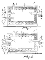
- the reference numeral 1 generally designates an intermittent combustion kiln, particularly for ceramic articles.
- the kiln 1 comprises a chamber C made of refractory material, inside which the ceramic articles loaded therein, arranged on appropriate trucks, not shown because they are of the conventional type, are subjected to thermal treatment.
- a generic operating cycle of the kiln 1 provides for the following steps: loading of the unfired articles, preheating, high-temperature firing, cooling and unloading of the fired articles.
- first burners 2 of the type traditionally used in the ceramics sector and at least one second burner 3 of the regenerative type with heat recovery of the exhaust gases of the chamber C.
- the chamber C is further provided with a circuit for aspirating and evacuating the exhaust gases generated during the thermal treatment, which leads into a stack D.
- the first burners 2, of the aspirated or forced-draught type have a duct 4 for supplying the comburent air and a duct 5 for supplying the fuel.
- Each regenerative burner 3 comprises multiple regenerative exchangers with periodically complementary operation, which are distributed radially around the body of said burner 3, are connected to the chamber C and are associable with an intake for comburent air and with an outlet for the cold exhaust gases.
- Each regenerative exchanger is constituted by stacked lamination packs, between which channels remain; the hot exhaust gases that arrive from the chamber C and the incoming cold comburent air alternately flow through said channels.
- the hot exhaust gases that arrive from the chamber C flow between the laminations, and heat accumulates in the exchanger; then the exchanger is crossed by the incoming cold air, to which the accumulated heat is transferred; the exhaust gases are therefore cold when they exit from the regenerative burner 3, while the incoming comburent air is preheated.
- the regenerative exchangers with which the individual regenerative burner 3 is provided have a periodically complementary operation, i.e., while some of them are being crossed by the hot exhaust gases that arrive from the chamber C, the remaining exchangers are crossed by the incoming cold comburent air, and vice versa.
- the reference numeral 6 designates the fuel supply duct
- the reference numeral 7 designates the comburent air supply duct
- the reference numeral 8 designates the duct for the discharge of the cold exhaust gases of the regenerative burners 3.
- each regenerative burner 3 is provided with a single regenerative exchanger with alternating operation: in a first step, the exchanger is crossed by the hot exhaust gases that arrive from the chamber C and recovers and accumulates their residual heat; in a second step, the exchanger is crossed by the incoming cold comburent air, to which it transfers the previously accumulated heat.
- the kiln 1 is provided with pairs of regenerative burners 3, the burners of each pair having a periodically complementary operation: one burner introduces in the chamber C the hot combustion gases, and its respective regenerative exchanger is crossed by the incoming comburent air, to which it transfers heat, while the other burner draws the exhaust gases from the chamber C and its respective regenerative exchanger is crossed by the exhaust gases, from which it removes heat, accumulating it, and vice versa.
- Figure 1 illustrates a kiln 1 provided with a regenerative burner 3 of the type that comprises a plurality of regenerative heat exchangers with periodically complementary operation; accordingly, the burner 3 has an independent and autonomous operation.
- Figure 2 illustrates a kiln 1 provided with two regenerative burners 3 (designated by the reference numerals 3a, 3b) of the type with a single regenerative exchanger.
- the regenerative burners 3 (3a, 3b) are opposite one another and operate in an alternately complementary manner: the burner 3a introduces in the chamber C the hot combustion gases, the respective exchanger being crossed by the incoming comburent air, while the other burner 3b aspirates from the chamber C the exhaust gases, the respective exchanger being crossed by the exhaust gases, the heat of which it recovers and accumulates, and vice versa.
- the regenerative burners 3 operate efficiently at temperatures above a minimum temperature between 800 and 1300°C; this interval corresponds to the stage for firing at high temperature of the entire thermal treatment to which the articles are subjected.
- the first burners 2 are shut down, while the regenerative burners 3 enter the active operating step; the regenerative burners 3 are therefore active when the first burners 2 are passive, and vice versa.
- the regenerative burners 3 are active during the step for the so-called firing of the articles loaded in the kiln 1, when the articles are kept, for a preset time interval, at the highest temperatures provided by the thermal treatment.
- the stack D is disconnected from the chamber C ( Figure 2); the exhaust gases are in fact aspirated and evacuated by means of the regenerative burners 3.
- the burners 2 and the regenerative burners 3 can be incorporated in a single block.
- the described invention achieves the proposed aim and objects, i.e., to provide an intermittent combustion kiln that allows to utilize fully the residual heat of the combustion gases and allows to limit consumption and energy costs.
Landscapes
- Engineering & Computer Science (AREA)
- Mechanical Engineering (AREA)
- General Engineering & Computer Science (AREA)
- Environmental & Geological Engineering (AREA)
- Waste-Gas Treatment And Other Accessory Devices For Furnaces (AREA)
- Tunnel Furnaces (AREA)
- Baking, Grill, Roasting (AREA)
Applications Claiming Priority (2)
| Application Number | Priority Date | Filing Date | Title |
|---|---|---|---|
| IT2000MO000251A IT1316951B1 (it) | 2000-11-23 | 2000-11-23 | Forno intermittente a combustione, particolarmente per manufatticeramici. |
| ITMO000251 | 2000-11-23 |
Publications (2)
| Publication Number | Publication Date |
|---|---|
| EP1209433A2 true EP1209433A2 (de) | 2002-05-29 |
| EP1209433A3 EP1209433A3 (de) | 2003-04-16 |
Family
ID=11450617
Family Applications (1)
| Application Number | Title | Priority Date | Filing Date |
|---|---|---|---|
| EP01127369A Withdrawn EP1209433A3 (de) | 2000-11-23 | 2001-11-21 | Nichtkontinuierlicher Verbrennungsofen, insbesondere für Keramikteile |
Country Status (2)
| Country | Link |
|---|---|
| EP (1) | EP1209433A3 (de) |
| IT (1) | IT1316951B1 (de) |
Cited By (1)
| Publication number | Priority date | Publication date | Assignee | Title |
|---|---|---|---|---|
| CN113432427A (zh) * | 2021-06-04 | 2021-09-24 | 成都日进冶金锻造有限公司 | 一种高效节能的蓄热式加热炉 |
Family Cites Families (2)
| Publication number | Priority date | Publication date | Assignee | Title |
|---|---|---|---|---|
| JPH1194239A (ja) * | 1997-09-26 | 1999-04-09 | Nippon Furnace Kogyo Kaisha Ltd | 交互切換蓄熱再生バーナシステム及びその燃焼制御方法 |
| JPH11223467A (ja) * | 1998-02-10 | 1999-08-17 | Ngk Insulators Ltd | セラミック焼成炉 |
-
2000
- 2000-11-23 IT IT2000MO000251A patent/IT1316951B1/it active
-
2001
- 2001-11-21 EP EP01127369A patent/EP1209433A3/de not_active Withdrawn
Cited By (1)
| Publication number | Priority date | Publication date | Assignee | Title |
|---|---|---|---|---|
| CN113432427A (zh) * | 2021-06-04 | 2021-09-24 | 成都日进冶金锻造有限公司 | 一种高效节能的蓄热式加热炉 |
Also Published As
| Publication number | Publication date |
|---|---|
| EP1209433A3 (de) | 2003-04-16 |
| ITMO20000251A0 (it) | 2000-11-23 |
| ITMO20000251A1 (it) | 2002-05-23 |
| IT1316951B1 (it) | 2003-05-13 |
Similar Documents
| Publication | Publication Date | Title |
|---|---|---|
| KR101581172B1 (ko) | 축열로 버너 | |
| KR100293836B1 (ko) | 기류로 | |
| GB2176583A (en) | Method of calcining solid materials and single column kiln therefor | |
| EP1209433A2 (de) | Nichtkontinuierlicher Verbrennungsofen, insbesondere für Keramikteile | |
| EP1209432A2 (de) | Durchlaufofen insbesondere für Keramikteile | |
| JP2909367B2 (ja) | 取鍋の乾燥および加熱方法 | |
| JP6086313B2 (ja) | 蓄熱式燃焼装置及び熱分解処理方法 | |
| JP5398686B2 (ja) | 加熱炉 | |
| KR100897734B1 (ko) | 도자기 소성로 | |
| JPH06228632A (ja) | 加熱設備およびそれを使用した加熱方法 | |
| EP0836066B1 (de) | Betrieb eines Ofens für Verfahren und Behandlungen in unterstoechiometrischen Atmosphären | |
| CN213955959U (zh) | 一种隧道窑热能循环利用系统 | |
| JP2004131515A (ja) | 蓄熱式室式コークス炉の端フリュー加熱システム | |
| KR101020358B1 (ko) | 재가열로의 배열회수장치 | |
| JPH10259996A (ja) | ローラハースキルンおよびその運転方法 | |
| JP2004003712A (ja) | 高温気体発生用バーナおよび高温気体発生方法 | |
| JP3414942B2 (ja) | 加熱炉 | |
| CN213955958U (zh) | 一种陶瓷烧制通风控制系统 | |
| JPH0320405A (ja) | 多帯式連続加熱炉の炉内温度変更方法 | |
| JPS60233490A (ja) | 竪型焼成炉 | |
| CN115654517A (zh) | 有机颗粒物废气的处理方法及处理设备 | |
| JPH11223467A (ja) | セラミック焼成炉 | |
| JP2001173917A (ja) | リジェネバーナ | |
| CN114838588A (zh) | 一种双炉腔窑炉 | |
| JPH1030887A (ja) | 炉頂予熱装置におけるスクラップの予熱方法 |
Legal Events
| Date | Code | Title | Description |
|---|---|---|---|
| PUAI | Public reference made under article 153(3) epc to a published international application that has entered the european phase |
Free format text: ORIGINAL CODE: 0009012 |
|
| AK | Designated contracting states |
Kind code of ref document: A2 Designated state(s): AT BE CH CY DE DK ES FI FR GB GR IE IT LI LU MC NL PT SE TR |
|
| AX | Request for extension of the european patent |
Free format text: AL;LT;LV;MK;RO;SI |
|
| PUAL | Search report despatched |
Free format text: ORIGINAL CODE: 0009013 |
|
| AK | Designated contracting states |
Designated state(s): AT BE CH CY DE DK ES FI FR GB GR IE IT LI LU MC NL PT SE TR |
|
| AX | Request for extension of the european patent |
Extension state: AL LT LV MK RO SI |
|
| RIC1 | Information provided on ipc code assigned before grant |
Ipc: 7F 23L 15/02 B Ipc: 7F 27B 17/00 B Ipc: 7F 27D 17/00 A |
|
| 17P | Request for examination filed |
Effective date: 20030919 |
|
| AKX | Designation fees paid |
Designated state(s): AT BE CH CY DE DK ES FI FR GB GR IE IT LI LU MC NL PT SE TR |
|
| 17Q | First examination report despatched |
Effective date: 20050426 |
|
| STAA | Information on the status of an ep patent application or granted ep patent |
Free format text: STATUS: THE APPLICATION IS DEEMED TO BE WITHDRAWN |
|
| 18D | Application deemed to be withdrawn |
Effective date: 20051108 |