EP1207658A2 - Blinde Kanalschätzung - Google Patents
Blinde Kanalschätzung Download PDFInfo
- Publication number
- EP1207658A2 EP1207658A2 EP01127073A EP01127073A EP1207658A2 EP 1207658 A2 EP1207658 A2 EP 1207658A2 EP 01127073 A EP01127073 A EP 01127073A EP 01127073 A EP01127073 A EP 01127073A EP 1207658 A2 EP1207658 A2 EP 1207658A2
- Authority
- EP
- European Patent Office
- Prior art keywords
- data coefficients
- data
- coefficients
- sequence
- transmission channel
- Prior art date
- Legal status (The legal status is an assumption and is not a legal conclusion. Google has not performed a legal analysis and makes no representation as to the accuracy of the status listed.)
- Withdrawn
Links
Images


Classifications
-
- H—ELECTRICITY
- H04—ELECTRIC COMMUNICATION TECHNIQUE
- H04L—TRANSMISSION OF DIGITAL INFORMATION, e.g. TELEGRAPHIC COMMUNICATION
- H04L25/00—Baseband systems
- H04L25/02—Details ; arrangements for supplying electrical power along data transmission lines
- H04L25/0202—Channel estimation
- H04L25/0238—Channel estimation using blind estimation
Definitions
- the present invention relates to data transmission via variable channels and especially on receivers and methods and apparatus for estimating a transmission channel.
- Transmission channels occur in particular if the transmission channels are free space transmission channels, such as they are present, for example, in mobile communications.
- the channel estimate is necessary for this, for example any channel equalization at the receiving end using a Undo equalizer.
- channel estimation methods are used in modern receivers used. These channel estimation methods are based insist that a known broadcast sequence from the broadcaster via the Transmission channel is transmitted to the receiver, and that the Receive sequence evaluated with knowledge of the send sequence to the transmission channel transfer function determine.
- FIG. 5 shows a general transmission system with a transmission filter 200, a transmission channel 300 and a reception filter 400.
- An input signal is fed into the transmission filter x (t) fed, which leads to an output signal y (t) leads at the output of the reception filter 400.
- the transmission filter determine the transmission channel and the receive filter the actual transmission channel or the actual one Transmission system, which are denoted by h (t) can.
- an input signal carries x (t) into the transmission channel 500 to an output signal y (t).
- the transmission system 500 can be in the time domain can be described by its impulse response h (t), which the convolution of the impulse response of the transmission filter with the impulse response of the channel and the impulse response of the Receiving filter corresponds.
- the output signal corresponds to y (t) in the time period of folding the impulse response of the Transmission channel h (t) with the input signal x (t).
- y (t) in the time period of folding the impulse response of the Transmission channel h (t) with the input signal x (t).
- the Fourier transform Y (f) as System transfer function S (f) multiplied by the Fourier transform the input sequence X (f).
- Channel estimation methods are based on the channel impulse response h (t) or the channel transfer function H (f) using a known input signal and the received one To calculate output signal.
- the input signal is the same as the output signal and the channel impulse response is a discrete sequence.
- An exact determination of the channel transfer function is theoretically only possible if an infinitely long known Input sequence is sent and then with an infinity long reception sequence is combined to the channel impulse response to calculate. In practice, however, must follow finite length can be used.
- the lengths are known Significant input sequences to a good one Channel estimate.
- the channel estimate therefore leads to a loss of transmission capacity.
- channel estimation method with known broadcast sequences to one considerable limitation of the useful capacity of a Transmission system lead when high quality of Channel estimation is to be achieved. Will the consequences on the other hand, chosen short to limit the overhead, so will only result in lower quality channel estimation results achieved.
- DE 19523327 C2 discloses a method for improved Estimate the impulse response of a transmission channel, where the signal is a training signal of a training sequence contains known information content.
- the course of the Training signal is at the receiver end of the transmission system sampled at certain times and saved.
- the training signal also becomes a estimated impulse response of the transmission system or a estimated transfer function determined.
- the transfer function can in a receiver-side equalizer be used.
- the object of the present invention is a Concept for better estimation of a transmission channel as well a receiver in which this concept is implemented create.
- This task is accomplished by a device for estimating a Transmission channel according to claim 1, a method for Estimating a transmission channel according to claim 13 or solved by a receiver according to claim 15.
- the present invention is based on the finding that that gone from the channel estimation with known broadcast sequences must be, and that the user data or any any receive data at the output of the transmission channel channel estimation must be used to get a good one Channel estimation on the one hand and no loss of transmission capacity on the other hand.
- the invention Concept for estimating a transmission channel includes an iterative procedure, in which the channel estimation with every iteration step is qualitatively better. The procedure is characterized by high convergence, such that only a limited number of iteration steps are required is to get a high quality channel estimate.
- the device according to the invention for estimating a transmission channel comprises a detection device for detection a sequence of data coefficients at the output of the transmission channel. Each of the data coefficients is marked with a Sign applied to that selected from the data coefficients is. Then the with this sign loaded data coefficient stored. The first This ends the iteration step. In the second iteration step a new sequence of data coefficients is acquired, again with one selected from these data coefficients Sign applied and then to the stored charged Data coefficients that are the result of the first Iteration step were obtained, added. Already after the second iteration step can be added from the Data coefficients an estimate for the system autocorrelation function or system auto-correlated of the transmission channel be derived.
- the iteration can be repeated any number of times.
- one Third step for example, is a new sequence of data coefficients detected at the output of the transmission channel, after which each data coefficient of this further sequence with a Sign of a data coefficient of this sequence is applied becomes.
- the set of applied data coefficients then becomes the accumulated data coefficients held in memory added.
- the data coefficients result then again an improved estimate for the system autocorrelation function of the transmission channel.
- the concept according to the invention is based on the system autocorrelation matrix of the transmission channel a number of rows and columns, this number being equal the number of channel coefficients. Every line or every System autocorrelation matrix column includes all information the system auto-correlated. So it has to be valued the system autocorrelation did not correlate the entire system autocorrelation matrix be calculated, but just any Row or any column of the same. Which Row or column of the system autocorrelation matrix calculated depends on which data coefficient the sign of the recorded sequence of data coefficients is used to add all other data coefficients to it apply. Becomes the sign of the first data coefficient is taken, then the first column of the system autocorrelation matrix estimated.
- the sign of the last data coefficient a data sequence is used for loading, the last column of the system autocorrelation matrix calculated.
- the applied data coefficients be re-sorted accordingly before adding. This possibility is due to the higher circuit complexity for example using a hardwired Resorting device not preferred, but can then make sense if there is uncertainty about the quality of a received data coefficient, and thus there are also uncertainties regarding the sign, although the inventive concept for estimating the transfer function is very robust against such errors.
- the concept according to the invention is advantageous in that that just simple iterative estimation operations the system autocorrelation function are required, namely applying a data coefficient to one certain signs, just a change of sign, if the sign is negative, or none at all Operation if the sign is positive. Furthermore is just a simple addition operation that can be implemented quickly to add up the data coefficients needed. There are no divisions or multiplications required.
- Another advantage of the present invention is that the added data coefficients are already qualitative System autocorrelation function without Play further arithmetic operations.
- To the system autocorrelation function to quantify only a simple scaling operation can be performed which as input value only the power of the input signal needed.
- the power of the input signal or the However, the square of the standard deviation of the same is special already known in digital transmission systems, without having to know the input sequence itself. Such digital If possible, transmission systems are always operated that the power of the transmitted signal is essentially is constant over time.
- Another advantage of the present invention is that continuous on-line monitoring of the transmission channel so to speak as a "waste product" of the reception process is possible, so that no transmission of user data must be interrupted to get a channel estimate however, as is required when a known input data sequence should be used.
- Another advantage of the present invention is that with continuous monitoring of the channel any number Iteration steps are performed so that the estimate will be as accurate if the channel is not too strong changes. Because of the high convergence of the invention However, a concept also applies to continuous channel monitoring rapid changes in the channel very quickly in the Channel estimation come to light. This is a procedure not possible for channel estimation with known user data sequence, because nobody knows when a channel change took place has, so that it is not possible at the exact time send a known user data sequence to a channel change, in order to be able to determine the changed channel exactly then.
- Another advantage of the present invention is that the system autocorrelation function easily for example using a fast Fourier transform can be transformed into the frequency domain in order to to maintain the spectral power density of the channel. Becomes the root is formed from the spectral power density of the channel, so the amount transfer function is easily obtained over the frequency of the channel such that a Channel equalizers can be controlled directly with this data can be a fast and effective adaptive channel equalization with regard to the amplitude response without to be able to carry out significant circuitry.
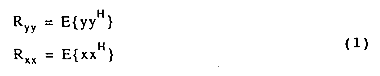
- R yy is the autocorrelation matrix of the output signal
- R xx is the autocorrelation matrix of the input signal.
- E ⁇ ... ⁇ denotes the expected value. There are several ways of calculating an expected value, for example simply by averaging over time or other measures known in the art in order to eliminate the noise processes.
- H represents the Hermitian operator, which is known to include a transposition and a conjugation.
- T means transposition.
- the autocorrelation sequence r yy [r yy (0) ... r yy (N)] represents the basis for the formation of the autocorrelation matrix R yy of the following form:
- the indices i and k here mean time indices or the number of an input data coefficient in the sequence of input data coefficients.
- the following expression results for the variance ⁇ : E ⁇ xx H ⁇ ⁇ 2 ⁇ I
- I means the unit matrix of the dimension (n + 1, n + 1).
- the matrix R hh can be brought to the required dimension simply by filling with zeros.
- the index p denotes the highest coefficient of the system autocorrelation function and that the index 0 denotes the first coefficient of the system autocorrelation function, so that the system autocorrelation function has a total of (p + 1) coefficients.
- the expression (p + 1) represents the degree of Channel, ie the length of the channel's system autocorrelation function.
- the number of data coefficients of the sequence of data coefficients is selected so that it is equal to the number of system autocorrelation function coefficients of the channel, d. H. that the number of data coefficients of a detected sequence equal to the degree of the channel is.
- y 0 is a scalar coefficient. It should also be noted that the system auto-correlated according to equation (9) is estimated in its conjugated form, which does not matter, however, since another conjugation can be used to switch from the conjugated form back to the unconjugated form.
- equation (11) means that the signal power of the input signal is evenly distributed over the real and the imaginary part of the transmission sequence x.
- r hh (0) denotes the system energy, ie the first coefficient of r hh (see equation (8)).
- Equation (17) specifies the multiplication-free algorithm for estimating the system's auto-correlation function.
- Equation (7) the concept of the invention to estimate a transmission channel, albeit the same above based on the determination of the first column of the system autocorrelation matrix (Equation (7)) has been explained, using all elements of the matrix in equation (7) can be carried out, so that cases are conceivable where only certain parts of the system autocorrelation matrix are determined become.
- equation (17) can be simplified to equation (19).
- E ⁇ sign (real (y 0 )) ⁇ Y ⁇ E ⁇
- Equation (19) represents an iterative process, although the iteration rule is only implicitly present in equation (19).
- E the expected value of the sign of the real part of the first received coefficient of a data sequence multiplied by the received data sequence
- Fig. 1 for a device for estimating a transmission channel according to the present To represent invention.
- the transmission channel that is in Fig. 1 is generally shown at 10, receives on the input side an input data sequence x to an output data sequence on the output side output y.
- the input data sequence x must not be known in the inventive concept.
- the Output sequence y is fed into a detection device 12, which is always a sequence of data coefficients detected. Having a sequence of data coefficients, for example with 20 data coefficients this sequence is supplied to an application device 14, around as expressed in Equation (19) and Equation (20) with the sign of a data coefficient, for example the sign of the real part of the first data coefficient to be charged.
- the set of applied data coefficients is then fed to a memory 16, the memory 16 furthermore has an output 18 through which the memory content is output can be.
- the first sentence is already a first estimate of applied data coefficients for the system autocorrelation function of the transmission channel.
- the device according to the invention comprises a Means 20 for controlling the iterations.
- the device 20 controls the detection device and the Pressurization device to a renewed set of pressurized To form data coefficients. If the other Set of ordered data coefficients at an output 22 the application device 14 is present, it becomes the same fed to an adder 24.
- the adder 24 also receives from the memory 16 via an input 26 the previous one Memory contents. The adder 24 then performs coefficient-wise Addition by to add a set of Obtain data coefficients, which via an adder output 28 can be written back into the memory. Preferably the old memory content is added with the Data coefficients overwritten.
- control device 20 makes a corresponding one Control of the detection device, the application device, the memory and the adder, so that another set of added data coefficients which is an even better estimate for the system autocorrelation function of the transmission channel represents.
- FIG. 2 shows a schematic implementation of part of the device according to the invention from FIG. 1.
- the detection device 12 from FIG. 1 is shown schematically in FIG. 2 by a serial / parallel converter 30.
- the serial arriving data coefficients y d (n) arriving at the output of the transmission channel 10 of FIG. 1 are converted serial / parallel.
- the width of the serial / parallel converter defines the number of data coefficients in a sequence of data coefficients.
- Each data coefficient has its own parallel processing branch 32a to 32i.
- the sign of the real part of the first data coefficient of the sequence is selected in FIG. 2 merely by way of example. This sign is used to apply this to every data coefficient y d, i . This is done by multipliers 14a to 14i.
- the applied data coefficients are finally fed into the memory 16.
- Each loaded data coefficient receives its own memory cell, as shown in FIG. 2.
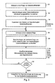
- FIG. 3 Process shown in flowchart form.
- a sequence of data coefficients detected In a first step 50, a sequence of data coefficients detected. Then in a second step 52 each data coefficient of the sequence of data coefficients with a selected sign to one Obtain set of applied data coefficients. The Set of applied data coefficients is then in one Step 54 saved. This is the first iteration step completed.
- a second iteration step another sequence is created of data coefficients as detected by block 56 is pictured.
- the further sequence of data coefficients is then again applied with a selected sign, another set of applied data coefficients to get as represented by a block 58 is.
- block 60 is indicated in Fig. 3, a coefficient-wise addition the further set of data coefficients to the previous one Memory content carried out.
- a step 62 it is then determined whether there are further iterations are desired. If no further iterations are desired, the iteration process is already after the second iteration step completed in a step 64 the memory content as an estimate for the system autocorrelation function of the transmission channel. This Estimate will not be of the best quality yet, however already similarities to the actual system autocorrelation function.
- step 62 A better estimate will be obtained if it is determined in step 62 that there are still more iterations are desired. If this is the case, then jumped back to block 56 for another sequence capture which then again with a selected sign is applied, whereupon again a coefficient Adding takes place etc. In this way and Ways can be any number of iteration steps be carried out to an arbitrarily accurate estimate for the system autocorrelation function of the transmission channel to obtain.
- inventive method especially for continuous monitoring of a transmission channel is suitable as it is very simple in terms of hardware and can therefore be implemented quickly.
- the memory content is always after the system autocorrelation function after a certain delay of the transmission channel with a good approximation.
- the actual coefficients are not shown the system autocorrelation function in memory, but multiplied by the factor C.
- the system autocorrelation function By one quantitative estimate for the system autocorrelation function to get the added up coefficients divided by the scaling factor C and further by the number of iteration steps performed in order to the actual coefficients of the system autocorrelation function to obtain.
- the same an FFT processor downstream of the memory in the If the frequency range is transformed the result is immediate the channel's power transfer function, which in turn, after a root value formation, the amount transfer function immediately of the channel, which in particular of great importance for adaptive channel equalization is.
- one in the recipient existing adaptive equalizer continuously controlled can be used to with no known input sequences the channel during the transmission of user data adaptively equalize. The channel doesn't change too much fast, so that optimal channel utilization with less Bit error rate reached.
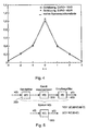
- FIG. 4 is a simulation example.
- the one in Fig. 4 shown simulation is a mobile radio channel with four Coefficients (propagation paths).
- Eb / N0 10 dB
- Eb / N0 40 dB accepted.
- the length of the simulated sequence was 100 Symbols. It should be noted that in the case of FIG not shown the memory content of the memory 16 was taken immediately, but that the scaling has been calculated out, and that also a division by the number of iteration steps has been carried out.
- the Number of data coefficients in a recorded sequence of Data coefficients i.e. the number of processed in parallel Branches chosen equal to 4.
- a trial run can be carried out, which consists of a larger number of data coefficients in a sequence of To collect data coefficients, then after a certain Number of iteration steps to determine whether in the Memory 16 there are added data coefficients, which are equal to 0, or which are smaller than a certain one Are threshold. If the simulation example shown in Fig.
- the subject of the present invention thus includes a Process with which a computationally efficient estimate of the System auto-correlated can be done.
- the essential The advantage of the method is that there is no need for multiplication and division operations, resulting in a very efficient Hardware implementation leads.
Landscapes
- Engineering & Computer Science (AREA)
- Power Engineering (AREA)
- Computer Networks & Wireless Communication (AREA)
- Signal Processing (AREA)
- Cable Transmission Systems, Equalization Of Radio And Reduction Of Echo (AREA)
Abstract
Description
- Fig. 1
- ein Blockschaltbild einer Vorrichtung zum Schätzen eines Übertragungskanals;
- Fig. 2
- ein Beispiel für eine detailliertere Darstellung der erfindungsgemäßen Vorrichtung von Fig. 1;
- Fig. 3
- ein Flußdiagramm, das das erfindungsgemäße Verfahren veranschaulicht;
- Fig. 4
- ein Simulationsbeispiel; und
- Fig. 5
- eine allgemeine Darstellung zur Erläuterung eines Übertragungskanals, in den ein Eingangssignal eingegeben wird, und aus dem ein Ausgangssignal ausgegeben wird.




Claims (15)
- Vorrichtung zum Schätzen einer Systemautokorrelationsfunktion eines Übertragungskanals (10), mit folgenden Merkmalen:einer Erfassungseinrichtung (12) zum Erfassen einer Folge von über den Übertragungskanal übertragenen Datenkoeffizienten am Ausgang des Übertragungskanals (10), wobei jeder Datenkoeffizient ein Vorzeichen hat;einer Beaufschlagungseinrichtung (14) zum Beaufschlagen jedes Datenkoeffizienten der Folge von Datenkoeffizienten mit einem Vorzeichen, das aus den Vorzeichen der Datenkoeffizienten ausgewählt ist, um einen Satz von beaufschlagten Datenkoeffizienten zu erhalten;einer Einrichtung (16) zum Speichern des Satzes von beaufschlagten Datenkoeffizienten;einer Einrichtung zum Erfassen und Verarbeiten einer weiteren Folge von Datenkoeffizienten durch Beaufschlagen jedes Datenkoeffizienten der weiteren Folge von Datenkoeffizienten mit einem Vorzeichen, das aus den Vorzeichen der Datenkoeffizienten der weiteren Folge von Datenkoeffizienten ausgewählt ist, um einen weiteren Satz von beaufschlagten Datenkoeffizienten zu erhalten; undeiner Additionseinrichtung (24) zum koeffizientenweisen Addieren des weiteren Satzes von beaufschlagten Datenkoeffizienten zu dem Satz von beaufschlagten Datenkoeffizienten, um einen Satz von aufaddierten Datenkoeffizienten zu erhalten, wobei der Satz von aufaddierten Datenkoeffizienten eine Schätzung für die Systemautokorrelationsfunktion des Übertragungskanals (10) darstellt.
- Vorrichtung nach Anspruch 1, die ferner folgendes Merkmal aufweist:eine Steuerungseinrichtung (20)zum Steuern der Speichereinrichtung (16), daß sie den Satz von aufaddierten Datenkoeffizienten speichert,zum Steuern der Einrichtung zum Erfassen und Verarbeiten, um aus noch einer weiteren Folge von Datenkoeffizienten einen noch weiteren Satz von beaufschlagten Datenkoeffizienten zu erhalten; undzum Steuern der Additionseinrichtung (24) zum Addieren des noch weiteren Satzes von beaufschlagten Datenkoeffizienten zu dem Satz von aufaddierten Datenkoeffizienten, um einen verbesserten Schätzwert für die Systemautokorrelationsfunktion des Übertragungskanals (10) zu erhalten.
- Vorrichtung nach Anspruch 2,
bei der die Steuerungseinrichtung (20) angeordnet ist, um eine vorbestimmte Anzahl von Iterationen (N) unter Verwendung einer vorbestimmten Anzahl von Folgen von Datenkoeffizienten durchzuführen, um als Ergebnis der letzten Iteration einen weiter verbesserten Schätzwert nach einer N-ten Iteration zu erhalten. - Vorrichtung nach einem der vorhergehenden Ansprüche,
bei der die Beaufschlagungseinrichtung (14) ausgebildet ist, um beim Beaufschlagen der Datenkoeffizienten der Folge von Datenkoeffizienten und beim Beaufschlagen der Datenkoeffizienten der weiteren Folge von Datenkoeffizienten das Vorzeichen des gleichen Koeffizienten in der jeweiligen Folge von Datenkoeffizienten zu verwenden. - Vorrichtung nach einem der vorhergehenden Ansprüche,
bei der die Beaufschlagungseinrichtung (14) ausgebildet ist, um beim Beaufschlagen immer ein Vorzeichen des ersten Koeffizienten in der jeweiligen Folge zu verwenden. - Vorrichtung nach einem der vorhergehenden Ansprüche,
bei der die Datenkoeffizienten komplex sind und einen Realteil und einen Imaginärteil aufweisen, und bei dem die Beaufschlagungseinrichtung ausgebildet ist, um beim Beaufschlagen immer das Vorzeichen des Realteils eines Datenkoeffizienten zu verwenden. - Vorrichtung nach einem der vorhergehenden Ansprüche, die ferner folgendes Merkmal aufweist:eine Rechnereinrichtung zum Teilen jedes aufaddierten Datenkoeffizienten durch eine Anzahl (N) der Iterationsschritte, um skalierte aufaddierte Datenkoeffizienten zu erhalten.
- Vorrichtung nach einem der vorhergehenden Ansprüche, bei der die Einrichtung (20) zum Erfassen und Verarbeiten einer weiteren Folge von Datenkoeffizienten als Steuereinrichtung zum Steuern der Erfassungseinrichtung (12) und der Beaufschlagungseinrichtung (14) ausgeführt ist, um aus einer weiteren Folge von Datenkoeffizienten einen weiteren Satz von beaufschlagten Datenkoeffizienten zu erhalten.
- Vorrichtung nach Anspruch 8,
bei der die Rechnereinrichtung ausgebildet ist, um die Systemautokorrelationsfunktion in den Frequenzbereich zu transformieren, um eine Schätzung für die spektrale Leistungsdichte des Übertragungskanals (10) zu erhalten. - Vorrichtung nach Anspruch 9,
bei der die Rechnereinrichtung ferner ausgebildet ist, um die Wurzel aus der Schätzung für die spektrale Leistungsdichte des Kanals zu berechnen, um eine Schätzung für den Betragsfrequenzgang des Kanals zu erhalten. - Vorrichtung nach einem der vorhergehenden Ansprüche, die ferner folgendes Merkmal aufweist:eine Einrichtung zum Ermitteln des Grads des Übertragungskanals zum Untersuchen der Schätzung für die Systemautokorrelationsfunktion des Übertragungskanals, wobei der Grad des Übertragungskanals die Anzahl von Koeffizienten der Systemautokorrelationsfunktion entspricht, die größer als ein vorbestimmter Schwellenwert sind.
- Vorrichtung nach Anspruch 11, bei der die Erfassungseinrichtung (12) ausgebildet ist, um nach einer Anzahl von Iterationen die Anzahl von Datenkoeffizienten in einer Folge von Datenkoeffizienten so zu wählen, daß die Anzahl gerade gleich dem Grad des Kanals ist.
- Verfahren zum Schätzen einer Systemautokorrelationsfunktion eines Übertragungskanals, mit folgenden Schritten:in einer ersten Iterationsstufe:in einer zweiten Iterationsstufe:Erfassen (50) einer Folge von über den Übertragungskanal übertragenen Datenkoeffizienten an einem Ausgang des Übertragungskanals (10), wobei jeder Datenkoeffizient ein Vorzeichen hat;Beaufschlagen (52) jedes Datenkoeffizienten der Folge von Datenkoeffizienten mit einem Vorzeichen, das aus den Vorzeichen der Datenkoeffizienten ausgewählt ist, um einen Satz von beaufschlagten Datenkoeffizienten zu erhalten; undSpeichern (54) des Satzes von beaufschlagten Datenkoeffizienten;Erfassen (56) einer weiteren Folge von Datenkoeffizienten am Ausgang des Übertragungskanals;Beaufschlagen (58) jedes Datenkoeffizienten der weiteren Folge von Datenkoeffizienten mit einem Vorzeichen, das aus den Vorzeichen der Datenkoeffizienten ausgewählt ist, um einen weiteren Satz von beaufschlagten Datenkoeffizienten zu erhalten;koeffizientenweises Addieren (60) des weiteren Satzes von beaufschlagten Datenkoeffizienten zu dem einen Satz von beaufschlagten Datenkoeffizienten, um einen Satz von aufaddierten Datenkoeffizienten zu erhalten, wobei der Satz von aufaddierten Datenkoeffizienten eine Schätzung für die Systemautokorrelationsfunktion des Übertragungskanals (10) darstellt.
- Verfahren nach Anspruch 13, das folgende weitere Schritte aufweist:in einer dritten Iterationsstufe:Speichern des Satzes von aufaddierten Datenkoeffizienten;Erzeugen noch einer weiteren Folge von beaufschlagten Datenkoeffizienten durch Wiederholen der Schritte des Erfassens und Beaufschlagens; undkoeffizientenweises Aufaddieren des erhaltenen Satzes von beaufschlagten Datenkoeffizienten zu dem gespeicherten Satz von aufaddierten Datenkoeffizienten, um einen weiteren Satz von aufaddierten Datenkoeffizienten zu erhalten, wobei der weitere Satz von aufaddierten Datenkoeffizienten eine verbesserte Schätzung für die Systemautokorrelationsfunktion des Übertragungskanals darstellt.
- Empfänger mit folgenden Merkmalen:einer Vorrichtung zum Schätzen einer Systemautokorrelationsfunktion eines Übertragungskanals nach einem der Ansprüche 1 bis 12, um eine Schätzung für die Systemautokorrelationsfunktion des Kanals zu liefern; undeiner Einrichtung zum Entzerren von Empfangssignalen unter Verwendung der Schätzung für die Systemautokorrelationsfunktion des Kanals.
Applications Claiming Priority (2)
| Application Number | Priority Date | Filing Date | Title |
|---|---|---|---|
| DE10056824 | 2000-11-16 | ||
| DE2000156824 DE10056824C2 (de) | 2000-11-16 | 2000-11-16 | Vorrichtung und Verfahren zum Schätzen einer Systemautokorrelationsfunktion eines Übertragungskanals und Empfänger |
Publications (2)
| Publication Number | Publication Date |
|---|---|
| EP1207658A2 true EP1207658A2 (de) | 2002-05-22 |
| EP1207658A3 EP1207658A3 (de) | 2006-01-04 |
Family
ID=7663528
Family Applications (1)
| Application Number | Title | Priority Date | Filing Date |
|---|---|---|---|
| EP01127073A Withdrawn EP1207658A3 (de) | 2000-11-16 | 2001-11-14 | Blinde Kanalschätzung |
Country Status (2)
| Country | Link |
|---|---|
| EP (1) | EP1207658A3 (de) |
| DE (1) | DE10056824C2 (de) |
Family Cites Families (1)
| Publication number | Priority date | Publication date | Assignee | Title |
|---|---|---|---|---|
| DE19523327C2 (de) * | 1995-06-27 | 2000-08-24 | Siemens Ag | Verfahren zur verbesserten Schätzung der Impulsantwort eines Übertragungskanals |
-
2000
- 2000-11-16 DE DE2000156824 patent/DE10056824C2/de not_active Expired - Fee Related
-
2001
- 2001-11-14 EP EP01127073A patent/EP1207658A3/de not_active Withdrawn
Non-Patent Citations (3)
| Title |
|---|
| AFKHAMIE K H ET AL: "Blind identification of FIR systems driven by Markov-like input signals" IEEE TRANSACTIONS ON SIGNAL PROCESSING IEEE USA, Bd. 48, Nr. 6, Juni 2000 (2000-06), Seiten 1726-1736, XP011058976 ISSN: 1053-587X * |
| DOUGLAS O'SHAUGHNESSY: "Speech Communication" 1987, ADDISON.WESLEY PUBLISHING COMPANY , XP002350988 ISBN: 0-201-16520-1 Chapter 6.3 "Time-Domain Parameters", page 211-219 * |
| TONG L ET AL: "BLIND IDENTIFICATION AND EQUALIZATION BASED ON SECOND-ORDER STATISTICS: A TIME DOMAIN APPROACH" IEEE TRANSACTIONS ON INFORMATION THEORY, IEEE SERVICE CENTER, PISCATAWAY, NJ, US, Bd. 40, Nr. 2, 1. März 1994 (1994-03-01), Seiten 340-349, XP000457425 ISSN: 0018-9448 * |
Also Published As
| Publication number | Publication date |
|---|---|
| EP1207658A3 (de) | 2006-01-04 |
| DE10056824A1 (de) | 2002-06-06 |
| DE10056824C2 (de) | 2003-01-02 |
Similar Documents
| Publication | Publication Date | Title |
|---|---|---|
| DE69025997T2 (de) | Diversity-Empfängeranordnung für die Verwendung bei der digitalen Funkübertragung mit Mitteln zur Zweigauswahl durch Abschätzung der Eigenschaften des Übertragungsweges | |
| EP0490427B1 (de) | Empfänger mit mindestens zwei Empfangszweigen | |
| EP0778687A2 (de) | Bestimmung der Zweigmetriken in einem Viterbi-Entzerrer | |
| DE102013217181A1 (de) | Verfahren und System zum Durchführen einer Spektralanalyse eines nicht stationären Signals in Echtzeit | |
| DE69121825T2 (de) | Verfahren und Gerät zur Messung der Eigenschaften eines Übertragungskanals durch Sendung eines Testsignals verwendet für die Berechnung der Kanalimpulsantwort | |
| DE2849997A1 (de) | Digitaler empfaenger fuer mehrfrequenzsignale | |
| DE2755308A1 (de) | Automatischer frequenzbereich-entzerrer mit kleinstem mittleren fehlerquadrat als korrekturkriterium | |
| DE19538996C2 (de) | Vorrichtung und Verfahren zum Schätzen von Filterkoeffizienten | |
| DE69634466T2 (de) | Mehrbenutzerempfang für CDMA | |
| DE2611906A1 (de) | Verfahren und schaltungsanordnungen zur blockquantisierung eines elektrischen signals | |
| DE69729373T2 (de) | Verfahren zur berechnung der impulsantwort und empfänger | |
| DE19749151A1 (de) | Adaptiver Entzerrer mit kreisförmig angeordneter Filtereingangsschaltung | |
| DE2125230B2 (de) | Verfahren und Schaltungsanordnung zur modifizierenden Verarbeitung digitaler Informationssignalfolgen | |
| DE69020889T2 (de) | Verfahren zur Bestimmung der Koeffizienten eines FIR-Filters bei Entzerrern. | |
| WO2004051865A2 (de) | Verfahren zur analyse der kanalimpulsantwort eines übertragungskanals | |
| DE60319557T2 (de) | Verfahren zur Verminderung der Anzahl der Bits pro Softbit | |
| EP1297669B1 (de) | Viterbi-entzerrung mittels vorausberechneter metrikinkremente | |
| DE2906156C2 (de) | Digitale Filteranordnung | |
| DE10056824C2 (de) | Vorrichtung und Verfahren zum Schätzen einer Systemautokorrelationsfunktion eines Übertragungskanals und Empfänger | |
| DE2704641A1 (de) | Digitalfilter | |
| DE19523327C2 (de) | Verfahren zur verbesserten Schätzung der Impulsantwort eines Übertragungskanals | |
| EP1316182B1 (de) | Verbesserte kanalentzerrung für mobilfunkempfänger | |
| DE4022381C2 (de) | Verwendung langer Digitalfilter bei Vorkommnis von Abrundungsfehlern | |
| EP0293620A1 (de) | Signalübertragungsverfahren | |
| DE19702321A1 (de) | Verfahren zum adaptiven Filtern einer Eingangsfolge aus Abtastwerten |
Legal Events
| Date | Code | Title | Description |
|---|---|---|---|
| PUAI | Public reference made under article 153(3) epc to a published international application that has entered the european phase |
Free format text: ORIGINAL CODE: 0009012 |
|
| AX | Request for extension of the european patent |
Free format text: AL;LT;LV;MK;RO;SI |
|
| RAP1 | Party data changed (applicant data changed or rights of an application transferred) |
Owner name: FRAUNHOFER-GESELLSCHAFT ZUR FOERDERUNG DERANGEWAND |
|
| PUAL | Search report despatched |
Free format text: ORIGINAL CODE: 0009013 |
|
| AK | Designated contracting states |
Kind code of ref document: A3 Designated state(s): AT BE CH CY DE DK ES FI FR GB GR IE IT LI LU MC NL PT SE TR |
|
| AX | Request for extension of the european patent |
Extension state: AL LT LV MK RO SI |
|
| 17P | Request for examination filed |
Effective date: 20060209 |
|
| AKX | Designation fees paid |
Designated state(s): AT BE CH CY DE DK ES FI FR GB GR IE IT LI LU MC NL PT SE TR |
|
| RAP1 | Party data changed (applicant data changed or rights of an application transferred) |
Owner name: FRAUNHOFER-GESELLSCHAFT ZUR FOERDERUNG DER ANGEWAN |
|
| 17Q | First examination report despatched |
Effective date: 20070523 |
|
| STAA | Information on the status of an ep patent application or granted ep patent |
Free format text: STATUS: THE APPLICATION IS DEEMED TO BE WITHDRAWN |
|
| 18D | Application deemed to be withdrawn |
Effective date: 20071003 |