EP1207014A1 - Procédé et installation de grenaillage par ultrasons des alvéoles annulaires d'attache des aubes sur un rotor - Google Patents
Procédé et installation de grenaillage par ultrasons des alvéoles annulaires d'attache des aubes sur un rotor Download PDFInfo
- Publication number
- EP1207014A1 EP1207014A1 EP01402918A EP01402918A EP1207014A1 EP 1207014 A1 EP1207014 A1 EP 1207014A1 EP 01402918 A EP01402918 A EP 01402918A EP 01402918 A EP01402918 A EP 01402918A EP 1207014 A1 EP1207014 A1 EP 1207014A1
- Authority
- EP
- European Patent Office
- Prior art keywords
- cell
- sonotrode
- balls
- sheath
- rotor
- Prior art date
- Legal status (The legal status is an assumption and is not a legal conclusion. Google has not performed a legal analysis and makes no representation as to the accuracy of the status listed.)
- Granted
Links
- 238000000034 method Methods 0.000 title claims abstract description 25
- 230000006835 compression Effects 0.000 claims abstract description 7
- 238000007906 compression Methods 0.000 claims abstract description 7
- 230000010355 oscillation Effects 0.000 claims abstract description 7
- 238000002604 ultrasonography Methods 0.000 claims abstract description 6
- 238000013459 approach Methods 0.000 claims abstract description 3
- 238000004381 surface treatment Methods 0.000 claims abstract description 3
- 238000009434 installation Methods 0.000 claims description 24
- 238000005422 blasting Methods 0.000 claims description 23
- 238000006073 displacement reaction Methods 0.000 claims description 9
- 238000005480 shot peening Methods 0.000 claims description 6
- 238000007789 sealing Methods 0.000 claims description 5
- 238000004519 manufacturing process Methods 0.000 claims description 3
- 239000003595 mist Substances 0.000 claims description 3
- 238000003780 insertion Methods 0.000 claims description 2
- 230000037431 insertion Effects 0.000 claims description 2
- 238000011282 treatment Methods 0.000 abstract description 12
- 238000010304 firing Methods 0.000 abstract 1
- DOSMHBDKKKMIEF-UHFFFAOYSA-N 2-[3-(diethylamino)-6-diethylazaniumylidenexanthen-9-yl]-5-[3-[3-[4-(1-methylindol-3-yl)-2,5-dioxopyrrol-3-yl]indol-1-yl]propylsulfamoyl]benzenesulfonate Chemical compound C1=CC(=[N+](CC)CC)C=C2OC3=CC(N(CC)CC)=CC=C3C(C=3C(=CC(=CC=3)S(=O)(=O)NCCCN3C4=CC=CC=C4C(C=4C(NC(=O)C=4C=4C5=CC=CC=C5N(C)C=4)=O)=C3)S([O-])(=O)=O)=C21 DOSMHBDKKKMIEF-UHFFFAOYSA-N 0.000 description 13
- 239000011324 bead Substances 0.000 description 9
- 230000015556 catabolic process Effects 0.000 description 3
- 238000006731 degradation reaction Methods 0.000 description 3
- 230000000712 assembly Effects 0.000 description 2
- 238000000429 assembly Methods 0.000 description 2
- 230000000295 complement effect Effects 0.000 description 2
- 238000009826 distribution Methods 0.000 description 2
- 230000000694 effects Effects 0.000 description 2
- 230000036316 preload Effects 0.000 description 2
- 229910000831 Steel Inorganic materials 0.000 description 1
- 239000000919 ceramic Substances 0.000 description 1
- 239000011325 microbead Substances 0.000 description 1
- 238000012545 processing Methods 0.000 description 1
- 210000003456 pulmonary alveoli Anatomy 0.000 description 1
- 239000010453 quartz Substances 0.000 description 1
- 238000005096 rolling process Methods 0.000 description 1
- VYPSYNLAJGMNEJ-UHFFFAOYSA-N silicon dioxide Inorganic materials O=[Si]=O VYPSYNLAJGMNEJ-UHFFFAOYSA-N 0.000 description 1
- 239000010959 steel Substances 0.000 description 1
- 230000001360 synchronised effect Effects 0.000 description 1
- 238000012549 training Methods 0.000 description 1
Images


Classifications
-
- B—PERFORMING OPERATIONS; TRANSPORTING
- B24—GRINDING; POLISHING
- B24B—MACHINES, DEVICES, OR PROCESSES FOR GRINDING OR POLISHING; DRESSING OR CONDITIONING OF ABRADING SURFACES; FEEDING OF GRINDING, POLISHING, OR LAPPING AGENTS
- B24B39/00—Burnishing machines or devices, i.e. requiring pressure members for compacting the surface zone; Accessories therefor
-
- B—PERFORMING OPERATIONS; TRANSPORTING
- B24—GRINDING; POLISHING
- B24B—MACHINES, DEVICES, OR PROCESSES FOR GRINDING OR POLISHING; DRESSING OR CONDITIONING OF ABRADING SURFACES; FEEDING OF GRINDING, POLISHING, OR LAPPING AGENTS
- B24B1/00—Processes of grinding or polishing; Use of auxiliary equipment in connection with such processes
- B24B1/04—Processes of grinding or polishing; Use of auxiliary equipment in connection with such processes subjecting the grinding or polishing tools, the abrading or polishing medium or work to vibration, e.g. grinding with ultrasonic frequency
-
- B—PERFORMING OPERATIONS; TRANSPORTING
- B24—GRINDING; POLISHING
- B24B—MACHINES, DEVICES, OR PROCESSES FOR GRINDING OR POLISHING; DRESSING OR CONDITIONING OF ABRADING SURFACES; FEEDING OF GRINDING, POLISHING, OR LAPPING AGENTS
- B24B39/00—Burnishing machines or devices, i.e. requiring pressure members for compacting the surface zone; Accessories therefor
- B24B39/02—Burnishing machines or devices, i.e. requiring pressure members for compacting the surface zone; Accessories therefor designed for working internal surfaces of revolution
- B24B39/026—Impact burnishing
-
- C—CHEMISTRY; METALLURGY
- C21—METALLURGY OF IRON
- C21D—MODIFYING THE PHYSICAL STRUCTURE OF FERROUS METALS; GENERAL DEVICES FOR HEAT TREATMENT OF FERROUS OR NON-FERROUS METALS OR ALLOYS; MAKING METAL MALLEABLE, e.g. BY DECARBURISATION OR TEMPERING
- C21D7/00—Modifying the physical properties of iron or steel by deformation
- C21D7/02—Modifying the physical properties of iron or steel by deformation by cold working
- C21D7/04—Modifying the physical properties of iron or steel by deformation by cold working of the surface
- C21D7/06—Modifying the physical properties of iron or steel by deformation by cold working of the surface by shot-peening or the like
-
- F—MECHANICAL ENGINEERING; LIGHTING; HEATING; WEAPONS; BLASTING
- F01—MACHINES OR ENGINES IN GENERAL; ENGINE PLANTS IN GENERAL; STEAM ENGINES
- F01D—NON-POSITIVE DISPLACEMENT MACHINES OR ENGINES, e.g. STEAM TURBINES
- F01D5/00—Blades; Blade-carrying members; Heating, heat-insulating, cooling or antivibration means on the blades or the members
- F01D5/12—Blades
- F01D5/28—Selecting particular materials; Particular measures relating thereto; Measures against erosion or corrosion
- F01D5/286—Particular treatment of blades, e.g. to increase durability or resistance against corrosion or erosion
-
- Y—GENERAL TAGGING OF NEW TECHNOLOGICAL DEVELOPMENTS; GENERAL TAGGING OF CROSS-SECTIONAL TECHNOLOGIES SPANNING OVER SEVERAL SECTIONS OF THE IPC; TECHNICAL SUBJECTS COVERED BY FORMER USPC CROSS-REFERENCE ART COLLECTIONS [XRACs] AND DIGESTS
- Y10—TECHNICAL SUBJECTS COVERED BY FORMER USPC
- Y10T—TECHNICAL SUBJECTS COVERED BY FORMER US CLASSIFICATION
- Y10T29/00—Metal working
- Y10T29/47—Burnishing
- Y10T29/479—Burnishing by shot peening or blasting
Definitions
- the invention relates to a method of surface treatment and setting in compression preload by shot peening of the wall of at least one annular cell substantially in the form of a dovetail, formed at the periphery of a rotor rim, said annular cell opening out the outside by an annular lateral mouth and having at least two cell ends which open into at least one respectively opening for the introduction of blades.
- nozzles can only project microbeads whose diameter is less than 1mm, and typically between 0.3mm and 0.5mm.
- the distribution of the balls, both in position and in speed, is done according to a Gaussian.
- the shot blasting carried out is low so as not to generate a too high roughness in the vicinity of the treated area, which results in limited surface hardening.
- the diameter of the projected balls being small, the stronger the shot blasting, the more the degradation of the state of surface is important.
- the method makes it possible to obtain a homogeneous distribution of the positions beads constituting a mist of beads.
- the fog balls of balls moving in random directions they hit the cavity walls from various angles, which improves the surface condition compared to the balls projected by a nozzle in a preferred direction.
- the displacement is substantially vertically the sonotrode, so that the vibrating surface is at the level of the lateral mouth of the socket.
- the volume in which the fog of balls is distributed being less than the volume obtained when the vibrating surface remains outside the mouth, the process requires a shot blasting treatment time shorter.
- At least three successive shot blasting operations are carried out of the wall, reversing the direction of rotation of the rotor rim each time approach one end of the cell.
- the entire wall of the annular cell is not subject to same time to the impact of balls, which entails risks of deformation of the cavity, in particular, of the socket containing the foot dawn, given the importance of the rim diameter in relation to its thickness. Treating the wall with three successive treatments allows to considerably compensate for the deformations of the rim.
- a deflector is placed in the enclosure.
- the deflector can be of substantially triangular geometry with sides parallel to the portions of divergent walls so as to reduce the blasting effect of the area between said deflector and the bottom of the cavity.
- the rotor part after having shot a first cell, we do turn the rotor part around its axis of rotation, so as to bring the closure means in the opening for introducing blades, the displacement is substantially vertically the sonotrode and the sheath towards the position low, the acoustic assembly is moved substantially horizontally comprising the sheath and the horn towards the opening for introducing a second annular cell which is brought opposite the sonotrode, and we again positions the sonotrode supporting the dose of beads and the sheath in their high shot blasting position for blasting said second annular cell.
- the dose of beads is easily retrieved in order to be either reused for a subsequent treatment, or be replaced.
- a dose of balls is used whose diameter is greater than 0.8mm.
- the balls used in the process according to the invention have a diameter larger than the diameter of the balls likely to be projected by a nozzle, so the shot blasting can be stronger while having a less significant surface degradation.
- the invention also relates to an installation for setting up implement the process.
- the installation may include a plurality of acoustic assemblies each comprising a sonotrode and a sheath, arranged around the rim rotor, said acoustic assemblies being able to move in a axial direction of the rotor rim.
- the installation comprises a third lower clearance the diameter of the balls formed between said vibrating surface arranged in said mouth and said mouth.
- the installation advantageously comprises a fourth lower set the diameter of the balls formed between one end of the sheath and the mouthpiece, which when the vibrating surface does not block the mouthpiece ensures the tightness of the enclosure.
- the various elements of the installation are arranged so that no ball can block said elements likely to move.
- the sonotrode and the sheath comprising the closure means have a geometry adapted to the shape of the cavity to be treated.
- the vibrating surface is of complementary shape to the mouthpiece and the means shutters are formed so as to properly seal the enclosure.
- the second displacement means are likely to move the shutter means and the sonotrode together.
- the first means of movement and the second means of displacement are advantageously able to be controlled simultaneously.
- the sheath and the sonotrode are placed in an intermediate position in which the space generated by the means for closing said sheath and the vibrating surface of said sonotrode constitutes a reservoir for the dose of beads. Then said sheath and said sonotrode supporting the dose of beads are moved together using of the same displacement. Finally, the sonotrode and / or the sealing means can be moved individually, depending on the geometry of the cavity to be treated until the vibrating surface respectively closes the mouth of the cavity and that the sealing means close off the cavity openings.
- the installation includes support means to support the rotor rim to be treated and drive means said support means for regularly rotating the cell annular.
- the installation advantageously includes means for expelling the dose of balls from the vibrating surface to a reservoir.
- the installation includes means for moving substantially horizontally the sonotrode and the sheath.
- a plurality of annular cells arranged indifferently on a rotor rim and having the same sections, can thus be treated with a same installation that is moved so as to position the sonotrode and the sheath opposite the cell in question.
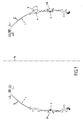
- FIG. 1 shows a rotor rim 1 comprising three cells annulars 2, formed at the periphery of the rotor rim 1 and distributed over different diameters of said rotor rim 1.
- These annular cells 2 are substantially dovetail-shaped and have a 2A mouthpiece substantially annular in shape.
- said cell 2 has a blade opening opening 5 visible in FIG. 3.
- Each blade root 4 is successively mounted by sliding in the insertion opening 5.
- One or more fixing device blades (not shown) allows the blades to be blocked 6.
- Figure 2 shows that the support between the walls of the cell 2 and the blade root 4 results in two contact lines 2B.
- the object of the invention is to propose a method and an installation to put in compression preload the wall 2C of each cell 2 and in particular the areas of the two contact lines 2B, so as to increase the wear resistance of these 2B contact lines caused by the friction between the blade root 4 and the wall of the cell 2 and so increase the fatigue strength of the rotor rim 1.
- Figure 3 shows an example of installation used for setting up process work and in which only one acoustic unit is used, said acoustic assembly positioned below the rotor rim 1 being likely to move vertically and horizontally.
- the rotor rim 1 is held by a mandrel 7 which can drive said rotor rim 1 rotating around its axis of rotation 1A, disposed at the horizontal.
- a sonotrode 8 the vibrating surface 8A of which is placed in a intermediate position in a sleeve 16, is movably mounted under the rim rotor 1.
- a dose of balls is placed above the vibrating surface 8a.
- the acoustic assembly comprising the sonotrode 8 and the sheath 16 is moved horizontally until the vibrating surface 8A of the sonotrode 8 is opposite cell 2 to be treated.
- the sonotrode 8 and the sheath 16 are moved vertically towards their high shot blasting position and the rotor rim is rotated to bring the vibrating surface 8A in the vicinity of a first end cell, 5A for example, so that shutter cheeks 14A and 14B formed on the sheath 16 are placed in the cell 2 so as to form a closed mobile enclosure 12.
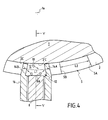
- said movable enclosure 12 is delimited by the wall portion 2'C, the vibrating surface 8A which closes the mouth portion 2A, the closing cheeks 14A and 14B and the sheath 16.
- the distance L1 between the two shutter cheeks 14A and 14B is substantially equal to the circumferential extent L2 of the opening introduction 5.
- Balls 10 with a diameter between 0.8mm and 5mm, preferably equal to 1mm, are projected by the vibrating surface 8A, oriented upwards, of the sonotrode 8 in the enclosure 12.
- FIG. 5 shows that the vibrating surface 8A is excited by a vibration generator 18, for example quartz, in order to create a fog of balls 10 in the enclosure 12.
- a deflector 15 which is carried by the shutter cheeks 14A and 14B can be placed in the fog of balls 10 in order to mitigate the blasting effect of the bottom of the cell and increase the shot blasting of the internal sides of the mouthpiece 21.
- Said deflector 15 is triangular with sides substantially parallel to the 2'C wall portions and at the bottom of the cell.
- the clearance e1 formed between the sonotrode 8 and the sheath 16 is less the diameter of the balls 10, so that no ball 10 can pass between the vibrating surface 8A and said sheath 16.
- the shutter cheeks 14A and 14B in dovetail shape have axial sections substantially complementary to those of cell 2, so that in the high shot peening position, the clearance e2 formed between each end cap 14A, 14B, and the portion of wall 2'C to be blasted is smaller than the diameter of the balls 10. Thus, no ball 10 can escape outside the enclosure 12.
- a first slide 20 makes it possible to carry out the displacements sonotrode 8 vertical by sliding said sonotrode 8 in the sheath 16.
- Control means allow control said first slide 20 and said second slide 22.
- Means for example rails, used to move the assembly acoustic comprising the sonotrode 8 and the sheath 16 horizontally, so as to position it next to a cell to be treated.
- the first slide 20 can be carried either by the second slide 22, as shown in Figure 5, either by the frame 24, in which case the control of the two slides 20 and 22 must be synchronized to mount together the sonotrode 8 and the sheath 16 towards the high position of shot blasting.
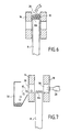
- the sonotrode 8 Before starting the treatment operation of an axial cell 2, the sonotrode 8 is placed in an intermediate position in the sheath 16, position in which the space delimited by the sheath 16 and the surface vibrating 8A, constitutes a container 26 which makes it possible to contain the dose of balls 10 which is deposited on the vibrating surface 8A, as shown in the figure 6.
- the sonotrode 8 and the sheath 16 are moved to the neighborhood of a first cell 2 to be treated and the opening is brought introduction 5 of said first cell 2 opposite the sonotrode 8, in rotating the rotor rim 1 around its axis of rotation 1A using drive means (not shown).
- Means of training include for example a motor.
- the sonotrode 8 and the sheath 16 are moved to their high position shot blasting by simultaneously moving, using the slide 22, the shutter cheeks 14A and 14B and the vibrating surface 8A in the opening 5, then rotate the rotor rim 1 until the two cheeks 14A and 14B are in the end 5A for example. Therefore, we proceeds to the peening of the wall portion 2'C of the first cell 2 in actuating the vibration generator 18 which generates a fog of balls 10 in the sealed mobile enclosure 12 and the rim is rotated regularly of rotor 1 around its axis of rotation 1A so as to blast the entire wall 2C.
- the sonotrode 8 is withdrawn towards its position low, represented figure 7, in which one proceeds to the release of the dose of balls 10.
- the balls 10 are for example blown from the surface 8A using a blower 28 through lights 30 formed in the sheath 16 and recovered in a tank 32. Said balls 10 can then be refreshed or replaced for further processing.
Landscapes
- Engineering & Computer Science (AREA)
- Mechanical Engineering (AREA)
- Chemical & Material Sciences (AREA)
- Materials Engineering (AREA)
- Crystallography & Structural Chemistry (AREA)
- Metallurgy (AREA)
- Organic Chemistry (AREA)
- General Engineering & Computer Science (AREA)
- Finish Polishing, Edge Sharpening, And Grinding By Specific Grinding Devices (AREA)
- Grinding And Polishing Of Tertiary Curved Surfaces And Surfaces With Complex Shapes (AREA)
Abstract
Description
- la figure 1 est une vue frontale d'une jante de rotor,
- la figure 2 est une vue frontale d'une aube de soufflante disposée dans une cavité annulaire formée à la périphérie de la jante de rotor,
- la figure 3 est une vue de l'installation, le fourreau et la sonotrode étant placés en position intermédiaire,
- la figure 4 est une coupe de l'installation selon un plan médian perpendiculaire à l'axe de rotation de la jante de rotor, le fourreau et la sonotrode étant placés en position haute de grenaillage,
- la figure 5 est une coupe de la figure 4 selon la ligne V-V,
- la figure 6 est une coupe du fourreau contenant la sonotrode, dans leur position intermédiaire, et
- la figure 7 est une coupe du fourreau contenant la sonotrode dans sa position basse.
Claims (14)
- Procédé de traitement de surface et de mise en précontrainte de compression par grenaillage de la paroi (2C) d'au moins une alvéole annulaire (2) sensiblement en forme de queue d'aronde, formée à la périphérie d'une jante de rotor (1), ladite alvéole annulaire (2) débouchant à l'extérieur par une embouchure latérale annulaire (2A) et présentant au moins deux extrémités (SA, 5B) d'alvéole qui débouchent dans respectivement au moins une ouverture d'introduction (5) d'aubes,
caractérisé par le fait qu'il comporte les étapes suivantes :a) on place une dose de billes (10) d'un diamètre déterminé sur une surface vibrante (8A) d'une sonotrode (8) préalablement disposée dans une position intermédiaire dans un fourreau (16) entourant ladite surface vibrante (8A), ledit fourreau (16) comportant des moyens d'obturation (14A, 14B) opposés susceptibles de coulisser dans l'alvéole (2),b) on place l'ouverture d'introduction (5) en regard de ladite sonotrode (8),c) on déplace sensiblement verticalement et ensemble ladite sonotrode (8) et ledit fourreau (16) vers ladite ouverture d'introduction (5) d'aubes pour les placer dans une position de grenaillage dans laquelle les moyens d'obturation (14A, 14B) sont en regard des extrémités (SA, 5B) d'alvéole débouchant dans ladite ouverture (5),d) on fait tourner la jante de rotor (1) autour de son axe de rotation (1A) disposé à l'horizontale de manière à amener les moyens d'obturation (14A, 14B) dans une première extrémité (5A) d'alvéole de manière à former une enceinte (12) mobile fermée contenant les billes (10), ete) on procède au grenaillage par ultrasons de l'intégralité de la paroi (2C) en générant un brouillard de billes (10) dans l'enceinte mobile (12) au moyen de la sonotrode (8) excitée par des moyens de production d'oscillations ultrasonores (18) et en faisant tourner régulièrement la jante de rotor (1) autour de son axe de rotation (1A) jusqu'à atteindre la deuxième extrémité d'alvéole. - Procédé selon la revendication 1, caractérisé par le fait que, après avoir déplacé ensemble la sonotrode (8) et le fourreau (16) dans la position de grenaillage, on déplace sensiblement verticalement la sonotrode (8), afin que la surface vibrante (8a) soit au niveau de l'embouchure latérale de l'alvéole (2).
- Procédé selon l'une des revendications 1 ou 2, caractérisé par le fait que l'on effectue au moins trois grenaillages successifs de la paroi (2C), en inversant le sens de rotation de la jante de rotor (1) à chaque approche d'une des extrémités d'alvéole.
- Procédé selon l'une quelconque des revendications 1 à 3, caractérisé par le fait que l'on place un déflecteur (15) dans l'enceinte (12).
- Procédé selon l'une quelconque des revendications 1 à 4, caractérisé par le fait que après avoir grenaillé une première alvéole, on fait tourner la partie de rotor (1) autour de son axe de rotation, de manière à amener les moyens d'obturation dans l'ouverture d'introduction (5) d'aubes, on déplace sensiblement verticalement la sonotrode (8) et le fourreau (16) vers la position basse, on déplace sensiblement horizontalement l'ensemble acoustique comprenant le fourreau (16) et la sonotrode (8) vers l'ouverture d'introduction (5) d'une seconde alvéole annulaire (2) qui est amenée en regard de la sonotrode (8), et on positionne à nouveau la sonotrode (8) supportant la dose de billes (10) et le fourreau (16) dans leur position haute de grenaillage pour grenailler ladite seconde alvéole annulaire (2).
- Procédé selon l'une quelconque des revendications 1 à 5, caractérisé par le fait que l'on utilise une dose de billes (10) dont le diamètre est supérieur à 0,8mm.
- Installation pour mettre en oeuvre le procédé selon l'une quelconque des revendications 1 à 6, caractérisée par le fait qu'elle comporteune sonotrode (8) susceptible de projeter des billes (10) d'un diamètre déterminé dans une enceinte mobile (12) délimitée par une portion de paroi (2'C) de l'alvéole annulaire (2), la surface vibrante (8A) de ladite sonotrode (8) disposée au voisinage de ladite embouchure (2A), et un fourreau (16) entourant la sonotrode (8) et ayant des moyens d'obturation (14A, 14B) susceptibles de former une enceinte mobile (12) étanche avec ladite portion de paroi (2'C) et ladite surface vibrante (8A),des moyens de production d'oscillations ultrasonores (18) susceptibles d'exciter ladite sonotrode (8),des premiers moyens (20) pour déplacer sensiblement verticalement ladite sonotrode (8), et des deuxièmes moyens (22) pour déplacer sensiblement verticalement lesdits moyens d'obturation (14A, 14B),un premier jeu (e1) inférieur au diamètre des billes (10) étant ménagé entre ladite sonotrode (8) et ledit fourreau (16), etun deuxième jeu (e2) inférieur au diamètre des billes (10) étant ménagé entre lesdits moyens d'obturation (14A, 14B) disposés dans ladite alvéole annulaire (2) et l'alvéole annulaire (2).
- Installation selon la revendication 7, caractérisée par le fait qu'elle comporte un troisième jeu (e3) inférieur au diamètre des billes (10) ménagé entre ladite surface vibrante (8A) disposée dans ladite embouchure (2A) et l'embouchure (2A).
- Installation selon l'une des revendications 7 ou 8, caractérisée par le fait qu'elle comporte un quatrième jeu (e4) inférieur au diamètre des billes (10) ménagé entre une extrémité (16A) du fourreau (16) et l'embouchure (2A).
- Installation selon l'une quelconque des revendications 7 à 9, caractérisée par le fait que les deuxièmes moyens de déplacement (22) sont susceptibles de déplacer ensemble les moyens d'obturation (14A, 14B) et la sonotrode (8).
- Installation selon l'une quelconque des revendications 7 à 10, caractérisée par le fait que les premiers moyens de déplacement (20) et les deuxièmes moyens de déplacement (22) sont aptes à être commandés simultanément.
- Installation selon l'une quelconque des revendications 7 à 11, caractérisée par le fait qu'elle comporte des moyens de support pour supporter la jante de rotor (1) à traiter et des moyens d'entraínement desdits moyens de support pour faire tourner régulièrement l'alvéole annulaire (2).
- Installation selon l'une quelconque des revendications 7 à 12, caractérisée par le fait qu'elle comprend des moyens (28) pour chasser la dose de billes (10) de la surface vibrante (8A) vers un réservoir (32).
- Installation selon l'une quelconque des revendications 7 à 13, caractérisée par le fait qu'elle comporte des moyens () pour déplacer sensiblement horizontalement la sonotrode (8) et le fourreau (16).
Applications Claiming Priority (2)
| Application Number | Priority Date | Filing Date | Title |
|---|---|---|---|
| FR0014769A FR2816537B1 (fr) | 2000-11-16 | 2000-11-16 | Procede et installation de grenaillage par ultrasons des alveoles annulaires d'attache d'aubes sur un rotor |
| FR0014769 | 2000-11-16 |
Publications (2)
| Publication Number | Publication Date |
|---|---|
| EP1207014A1 true EP1207014A1 (fr) | 2002-05-22 |
| EP1207014B1 EP1207014B1 (fr) | 2012-01-11 |
Family
ID=8856531
Family Applications (1)
| Application Number | Title | Priority Date | Filing Date |
|---|---|---|---|
| EP01402918A Expired - Lifetime EP1207014B1 (fr) | 2000-11-16 | 2001-11-14 | Procédé et installation de grenaillage par ultrasons des alvéoles annulaires d'attache des aubes sur un rotor |
Country Status (6)
| Country | Link |
|---|---|
| US (1) | US6508093B2 (fr) |
| EP (1) | EP1207014B1 (fr) |
| JP (1) | JP3879822B2 (fr) |
| CA (1) | CA2363276C (fr) |
| FR (1) | FR2816537B1 (fr) |
| SG (1) | SG101515A1 (fr) |
Cited By (4)
| Publication number | Priority date | Publication date | Assignee | Title |
|---|---|---|---|---|
| FR2907360A1 (fr) * | 2006-10-20 | 2008-04-25 | Sonats Soc Des Nouvelles Appli | Procedes et installations de grenailles. |
| WO2009067978A1 (fr) * | 2007-11-26 | 2009-06-04 | Eads Deutschland Gmbh | Procédé et dispositif pour le durcissement superficiel d'un élément composite métallique |
| EP2255926A1 (fr) * | 2004-07-30 | 2010-12-01 | Snecma | Procédé et dispositif de grenaillage par ultrasons |
| FR3061055A1 (fr) * | 2016-12-26 | 2018-06-29 | Safran Aircraft Engines | Dispositif pour le traitement d'une piece metallique, procede et ensemble de projectiles associes |
Families Citing this family (27)
| Publication number | Priority date | Publication date | Assignee | Title |
|---|---|---|---|---|
| US7028378B2 (en) * | 2000-10-12 | 2006-04-18 | Sonats-Societe Des Nouvelles Applications Des Techniques De Surfaces | Method of shot blasting and a machine for implementing such a method |
| US6526657B2 (en) * | 2001-05-07 | 2003-03-04 | General Electric Company | Methods for automated peening of tenons connecting turbine buckets and cover plates |
| US6993948B2 (en) * | 2003-06-13 | 2006-02-07 | General Electric Company | Methods for altering residual stresses using mechanically induced liquid cavitation |
| US7399371B2 (en) * | 2004-04-16 | 2008-07-15 | Nippon Steel Corporation | Treatment method for improving fatigue life and long-life metal material treated by using same treatment |
| DE102004029546A1 (de) * | 2004-06-19 | 2006-01-05 | Mtu Aero Engines Gmbh | Verfahren und Vorrichtung zum Oberflächenstrahlen von Gasturbinenschaufeln im Bereich ihrer Schaufelfüße |
| US20060021410A1 (en) * | 2004-07-30 | 2006-02-02 | Sonats-Societe Des Nouvelles Applications Des Techniques De Surfaces | Shot, devices, and installations for ultrasonic peening, and parts treated thereby |
| DE102004037954A1 (de) * | 2004-08-05 | 2006-03-16 | Mtu Aero Engines Gmbh | Vorrichtung zum Oberflächenstrahlen von Bauteilen |
| DE102004059592B4 (de) * | 2004-12-10 | 2014-09-04 | MTU Aero Engines AG | Verfahren zum Oberflächenstrahlen von Hohlräumen, insbesondere von Hohlräumen an Gasturbinen |
| WO2006124616A2 (fr) | 2005-05-12 | 2006-11-23 | General Electric Company | Traitement par ecrouissage aux ultrasons de composants assembles |
| JP4831807B2 (ja) * | 2005-06-14 | 2011-12-07 | 三菱重工業株式会社 | 超音波ショットピーニング装置及び超音波ショットピーニング方法 |
| WO2007055864A2 (fr) * | 2005-10-12 | 2007-05-18 | Surface Technology Holdings, Ltd | Machinerie turbo rotative optimisee a aubes formees d'un seul tenant et ses procede et appareil de realisation |
| JP5184747B2 (ja) * | 2005-12-13 | 2013-04-17 | 株式会社東芝 | 原子炉内構造物の超音波ショットピーニング施工装置および同施工方法 |
| DE102006016949A1 (de) * | 2006-04-11 | 2007-10-25 | Mtu Aero Engines Gmbh | Verfahren zum Herstellen eines Bauteils |
| US7665338B2 (en) * | 2006-10-20 | 2010-02-23 | Sonats-Societe Des Nouvelles Applications Des Techniques De Surfaces | Shot peening methods and units |
| DE102006058675A1 (de) * | 2006-12-13 | 2008-06-19 | Mtu Aero Engines Gmbh | Vorrichtung und Verfahren zum Oberflächenstrahlen eines Bauteils einer Gasturbine |
| DE502007002038D1 (de) * | 2007-04-12 | 2009-12-31 | Siemens Ag | Anlagen- und Vorrichtungskonzept für eine Shotpeeninganlage zum Verfestigen von Gasturbinen Laufschaufelfüssen |
| US20090095043A1 (en) * | 2007-10-11 | 2009-04-16 | Bunting Billie W | Conformable tooling for localized shot peening |
| US20090094829A1 (en) * | 2007-10-15 | 2009-04-16 | United Technologies Corporation | Method for ultrasonic peening of gas turbine engine components without engine disassembly |
| US8418332B2 (en) * | 2008-03-14 | 2013-04-16 | Varel International Ind., L.P. | Method of texturing a bearing surface of a roller cone rock bit |
| US8347683B2 (en) * | 2008-03-14 | 2013-01-08 | Varel International Ind., L.P. | Texturing of the seal surface for a roller cone rock bit |
| US8689907B2 (en) | 2010-07-28 | 2014-04-08 | Varel International Ind., L.P. | Patterned texturing of the seal surface for a roller cone rock bit |
| GB2492831A (en) * | 2011-07-14 | 2013-01-16 | Hkpb Scient Ltd | Workpiece surface modification during ultrasonic peening |
| JP5912916B2 (ja) * | 2012-06-27 | 2016-04-27 | 日立Geニュークリア・エナジー株式会社 | ショットピーニング方法 |
| US10493594B2 (en) * | 2016-04-12 | 2019-12-03 | General Electric Company | Apparatus and method for peening of machine components |
| CN114107633B (zh) * | 2021-11-22 | 2023-02-03 | 武汉理工大学 | 一种回转工件超声冲击强化装置及方法 |
| CN116713381B (zh) * | 2023-06-27 | 2024-06-07 | 中国航空制造技术研究院 | 一种带筋壁板的喷丸成形预弯工装及方法 |
| CN116749088B (zh) * | 2023-08-24 | 2023-11-03 | 新乡市豫能防爆科技有限公司 | 一种电机外壳加工装置 |
Citations (4)
| Publication number | Priority date | Publication date | Assignee | Title |
|---|---|---|---|---|
| US4426867A (en) * | 1981-09-10 | 1984-01-24 | United Technologies Corporation | Method of peening airfoils and thin edged workpieces |
| FR2689431A1 (fr) | 1992-04-06 | 1993-10-08 | Teknoson | Procédé et dispositif notamment de durcissement par ultrasons de pièces métalliques. |
| FR2714629A1 (fr) * | 1993-12-30 | 1995-07-07 | Teknoson Sa | Procédé et dispositif d'ébavurage de pièces mécaniques. |
| EP1101568A1 (fr) * | 1999-11-18 | 2001-05-23 | Snecma Moteurs | Procédé et machine de grenaillage par ultrasons de pièces sur une roue |
Family Cites Families (17)
| Publication number | Priority date | Publication date | Assignee | Title |
|---|---|---|---|---|
| US2460657A (en) * | 1944-12-22 | 1949-02-01 | Lancaster Processes Inc | Method and apparatus for peening the inside of tubes and other hollow bodies |
| US3482423A (en) * | 1968-02-26 | 1969-12-09 | Metal Improvement Co | Blade peening masking apparatus |
| US3675452A (en) * | 1970-03-18 | 1972-07-11 | Jury Anatolievich Osmolovsky | Device for surface hardening of parts |
| US3668913A (en) * | 1970-10-05 | 1972-06-13 | Metal Improvement Co | Apparatus for shot-peening turbine blades |
| US4419875A (en) * | 1981-09-10 | 1983-12-13 | Progressive Blasting Systems, Inc. | Article manipulator mechanism for accelerated shot treating apparatus |
| FR2713974B1 (fr) * | 1993-12-22 | 1996-01-19 | Snecma | Dispositif de grenaillage de surfaces non accessibles par une canalisation droite. |
| FR2715884B1 (fr) * | 1994-02-04 | 1996-04-12 | Gec Alsthom Electromec | Procédé et dispositif pour le traitement de surface et la mise en précontrainte de la paroi intérieure d'une cavité. |
| US5620307A (en) * | 1995-03-06 | 1997-04-15 | General Electric Company | Laser shock peened gas turbine engine blade tip |
| US5735044A (en) * | 1995-12-12 | 1998-04-07 | General Electric Company | Laser shock peening for gas turbine engine weld repair |
| US5671628A (en) * | 1995-12-18 | 1997-09-30 | General Electric Company | Laser shock peened dies |
| FR2743742B1 (fr) * | 1996-01-24 | 1998-04-03 | Seb Sa | Procede de traitement d'une surface metallique et de fabrication d'un article culinaire |
| US5950470A (en) * | 1998-09-09 | 1999-09-14 | United Technologies Corporation | Method and apparatus for peening the internal surface of a non-ferromagnetic hollow part |
| US5948293A (en) * | 1998-12-03 | 1999-09-07 | General Electric Company | Laser shock peening quality assurance by volumetric analysis of laser shock peened dimple |
| FR2791293B1 (fr) * | 1999-03-23 | 2001-05-18 | Sonats Soc Des Nouvelles Appli | Dispositifs de traitement de surface par impacts |
| US6170308B1 (en) * | 1999-07-20 | 2001-01-09 | United Technologies Corporation | Method for peening the internal surface of a hollow part |
| FR2801322B1 (fr) | 1999-11-18 | 2002-02-08 | Snecma | Procede de grenaillage par ultrasons de surfaces annulaires de grandes dimensions sur des pieces minces |
| US6340500B1 (en) * | 2000-05-11 | 2002-01-22 | General Electric Company | Thermal barrier coating system with improved aluminide bond coat and method therefor |
-
2000
- 2000-11-16 FR FR0014769A patent/FR2816537B1/fr not_active Expired - Lifetime
-
2001
- 2001-11-13 CA CA002363276A patent/CA2363276C/fr not_active Expired - Lifetime
- 2001-11-14 EP EP01402918A patent/EP1207014B1/fr not_active Expired - Lifetime
- 2001-11-15 JP JP2001350519A patent/JP3879822B2/ja not_active Expired - Lifetime
- 2001-11-16 SG SG200107172A patent/SG101515A1/en unknown
- 2001-11-16 US US09/987,857 patent/US6508093B2/en not_active Expired - Lifetime
Patent Citations (4)
| Publication number | Priority date | Publication date | Assignee | Title |
|---|---|---|---|---|
| US4426867A (en) * | 1981-09-10 | 1984-01-24 | United Technologies Corporation | Method of peening airfoils and thin edged workpieces |
| FR2689431A1 (fr) | 1992-04-06 | 1993-10-08 | Teknoson | Procédé et dispositif notamment de durcissement par ultrasons de pièces métalliques. |
| FR2714629A1 (fr) * | 1993-12-30 | 1995-07-07 | Teknoson Sa | Procédé et dispositif d'ébavurage de pièces mécaniques. |
| EP1101568A1 (fr) * | 1999-11-18 | 2001-05-23 | Snecma Moteurs | Procédé et machine de grenaillage par ultrasons de pièces sur une roue |
Cited By (7)
| Publication number | Priority date | Publication date | Assignee | Title |
|---|---|---|---|---|
| EP2255926A1 (fr) * | 2004-07-30 | 2010-12-01 | Snecma | Procédé et dispositif de grenaillage par ultrasons |
| FR2907360A1 (fr) * | 2006-10-20 | 2008-04-25 | Sonats Soc Des Nouvelles Appli | Procedes et installations de grenailles. |
| EP1914040A3 (fr) * | 2006-10-20 | 2008-06-18 | SONATS - Société des Nouvelles Applications des Techniques de Surfaces | Procédés et installations de grenaillage |
| WO2008047048A3 (fr) * | 2006-10-20 | 2008-11-13 | Sonats Soc Des Nouvelles Appli | Procedes et installations de grenaillage |
| WO2009067978A1 (fr) * | 2007-11-26 | 2009-06-04 | Eads Deutschland Gmbh | Procédé et dispositif pour le durcissement superficiel d'un élément composite métallique |
| FR3061055A1 (fr) * | 2016-12-26 | 2018-06-29 | Safran Aircraft Engines | Dispositif pour le traitement d'une piece metallique, procede et ensemble de projectiles associes |
| WO2018122523A1 (fr) * | 2016-12-26 | 2018-07-05 | Safran Aircraft Engines | Dispositif et procédé pour le traitement d'une piece metallique |
Also Published As
| Publication number | Publication date |
|---|---|
| FR2816537B1 (fr) | 2003-01-17 |
| FR2816537A1 (fr) | 2002-05-17 |
| US6508093B2 (en) | 2003-01-21 |
| CA2363276A1 (fr) | 2002-05-16 |
| JP3879822B2 (ja) | 2007-02-14 |
| EP1207014B1 (fr) | 2012-01-11 |
| SG101515A1 (en) | 2004-01-30 |
| CA2363276C (fr) | 2008-05-27 |
| JP2002166364A (ja) | 2002-06-11 |
| US20020069687A1 (en) | 2002-06-13 |
Similar Documents
| Publication | Publication Date | Title |
|---|---|---|
| CA2363276C (fr) | Procede et installation de grenaillage par ultrasons des alveoles annulaires d'attache d'aubes sur un rotor | |
| CA2363313C (fr) | Procede et dispositif de grenaillage par ultrasons des alveoles "axiales" d'attache des aubes sur un rotor | |
| EP1101568B1 (fr) | Procédé et machine de grenaillage par ultrasons de pièces sur une roue | |
| EP1203637B1 (fr) | Grenaillage transversal par ultrasons des aubes sur un rotor | |
| EP1208942B1 (fr) | Grenaillage des sommets des aubes refroidies | |
| EP1207013B1 (fr) | Procédé pour augmenter la durée de vie des attaches d'aubes sur un rotor | |
| CA2325897C (fr) | Procede de grenaillage par ultrasons de surfaces annulaires de grandes dimensions sur des pieces minces | |
| FR2873942A1 (fr) | Procede d'usinage d'ensembles carter de villebrequin/bloc- cylindres, ayant des pistes de glissement de cylindre traitees par projection | |
| FR2889669A1 (fr) | Piece metallique traitee par mise en compression de sous couches. procede pour obtenir une telle piece. | |
| FR2714629A1 (fr) | Procédé et dispositif d'ébavurage de pièces mécaniques. | |
| FR2873946A1 (fr) | Procede de preparation d'un alesage de cylindre moule, pour effectuer un revetement par voie thermique | |
| FR2873943A1 (fr) | Procede d'usinage avec enlevement de copeaux de pistes de glissement de cylindre soumises a une projection thermique | |
| FR2874027A1 (fr) | Procede de fabrication d'une surface de glissement de cylindres munie d'un revetement par voie thermique, avec un chanfrein d'extremite | |
| FR2874386A1 (fr) | Procede de fabrication d'une surface de glissement de cylindres munie d'un revetement par voie thermique, avec un chanfrein d'introduction | |
| WO2008029039A2 (fr) | Dispositif de traitement pour le grenaillage de la surface interieure d'une piece tubulaire | |
| FR2551996A1 (fr) | Procede et dispositif pour l'abaissement des tensions residuelles de fabrication sur la paroi interne d'un tube dudgeonne | |
| FR2815280A1 (fr) | Machine et procede de grenaillage | |
| FR2873948A1 (fr) | Procede de projection d'un fluide sur des surfaces de glissement de cylindres devant ulterieurement recevoir un revetement par voie thermique | |
| WO2002030619A1 (fr) | Procede de grenaillage et machine pour la mise en oeuvre d'un tel procede | |
| FR3142111A1 (fr) | Système d’ajustage et de précontrainte de la surface d’une pièce | |
| WO1998010892A1 (fr) | Dispositif de traitement de pieces par grenaillage, plus particulierement au moyen de billes d'acier mises en mouvement par un champ ultrasonore | |
| FR3165617A1 (fr) | Support d’essai de grenaillage | |
| EP0404674A1 (fr) | Procédé et dispositif d'amélioration de la résistance à la fatigue des ressorts hélicoidaux de compression et ressorts obtenus par ce procédé | |
| FR2800999A1 (fr) | Dispositif de denoyautage par voie mecanique de pieces creuses realisees a partir d'un procede de fonderie |
Legal Events
| Date | Code | Title | Description |
|---|---|---|---|
| PUAI | Public reference made under article 153(3) epc to a published international application that has entered the european phase |
Free format text: ORIGINAL CODE: 0009012 |
|
| 17P | Request for examination filed |
Effective date: 20011123 |
|
| AX | Request for extension of the european patent |
Free format text: AL;LT;LV;MK;RO;SI |
|
| AKX | Designation fees paid |
Designated state(s): DE FR GB IE IT NL |
|
| RAP1 | Party data changed (applicant data changed or rights of an application transferred) |
Owner name: SNECMA SERVICES Owner name: SNECMA |
|
| 17Q | First examination report despatched |
Effective date: 20090219 |
|
| RAP1 | Party data changed (applicant data changed or rights of an application transferred) |
Owner name: SNECMA |
|
| GRAP | Despatch of communication of intention to grant a patent |
Free format text: ORIGINAL CODE: EPIDOSNIGR1 |
|
| RIN1 | Information on inventor provided before grant (corrected) |
Inventor name: CHAREYRE, FRANCIS LUCIEN GUY Inventor name: SIMON, GUILLAUME FRANCOIS ROGER Inventor name: NTSAMA-ETOUNDI, MARIE-CHRISTINE MARCELLE Inventor name: KERNEIS, STEPHANE MICHEL Inventor name: HOFFMANN, HAKIM Inventor name: BERTHELET, BENOIT JEAN HENRI Inventor name: FRADIN, WILLY LIONEL |
|
| GRAS | Grant fee paid |
Free format text: ORIGINAL CODE: EPIDOSNIGR3 |
|
| RIN1 | Information on inventor provided before grant (corrected) |
Inventor name: SIMON, GUILLAUME FRANCOIS ROGER Inventor name: NTSAMA-ETOUNDI, MARIE-CHRISTINE MARCELLE Inventor name: HOFFMANN, HAKIM Inventor name: FRADIN, WILLY LIONEL Inventor name: CHAREYRE, FRANCIS LUCIEN GUY Inventor name: BERTHELET, BENOIT JEAN HENRI Inventor name: KERNEIS, STEPHANE MICHEL |
|
| GRAA | (expected) grant |
Free format text: ORIGINAL CODE: 0009210 |
|
| AK | Designated contracting states |
Kind code of ref document: B1 Designated state(s): DE FR GB IE IT NL |
|
| REG | Reference to a national code |
Ref country code: GB Ref legal event code: FG4D Free format text: NOT ENGLISH |
|
| REG | Reference to a national code |
Ref country code: IE Ref legal event code: FG4D |
|
| REG | Reference to a national code |
Ref country code: DE Ref legal event code: R096 Ref document number: 60145934 Country of ref document: DE Effective date: 20120308 |
|
| REG | Reference to a national code |
Ref country code: NL Ref legal event code: VDEP Effective date: 20120111 |
|
| PG25 | Lapsed in a contracting state [announced via postgrant information from national office to epo] |
Ref country code: NL Free format text: LAPSE BECAUSE OF FAILURE TO SUBMIT A TRANSLATION OF THE DESCRIPTION OR TO PAY THE FEE WITHIN THE PRESCRIBED TIME-LIMIT Effective date: 20120111 |
|
| REG | Reference to a national code |
Ref country code: IE Ref legal event code: FD4D |
|
| PG25 | Lapsed in a contracting state [announced via postgrant information from national office to epo] |
Ref country code: IE Free format text: LAPSE BECAUSE OF FAILURE TO SUBMIT A TRANSLATION OF THE DESCRIPTION OR TO PAY THE FEE WITHIN THE PRESCRIBED TIME-LIMIT Effective date: 20120111 |
|
| PLBE | No opposition filed within time limit |
Free format text: ORIGINAL CODE: 0009261 |
|
| STAA | Information on the status of an ep patent application or granted ep patent |
Free format text: STATUS: NO OPPOSITION FILED WITHIN TIME LIMIT |
|
| 26N | No opposition filed |
Effective date: 20121012 |
|
| REG | Reference to a national code |
Ref country code: DE Ref legal event code: R097 Ref document number: 60145934 Country of ref document: DE Effective date: 20121012 |
|
| REG | Reference to a national code |
Ref country code: FR Ref legal event code: PLFP Year of fee payment: 15 |
|
| REG | Reference to a national code |
Ref country code: FR Ref legal event code: PLFP Year of fee payment: 16 |
|
| REG | Reference to a national code |
Ref country code: FR Ref legal event code: PLFP Year of fee payment: 17 |
|
| REG | Reference to a national code |
Ref country code: FR Ref legal event code: CD Owner name: SAFRAN AIRCRAFT ENGINES, FR Effective date: 20170717 |
|
| REG | Reference to a national code |
Ref country code: FR Ref legal event code: PLFP Year of fee payment: 18 |
|
| PGFP | Annual fee paid to national office [announced via postgrant information from national office to epo] |
Ref country code: DE Payment date: 20201020 Year of fee payment: 20 Ref country code: IT Payment date: 20201021 Year of fee payment: 20 Ref country code: FR Payment date: 20201021 Year of fee payment: 20 Ref country code: GB Payment date: 20201021 Year of fee payment: 20 |
|
| REG | Reference to a national code |
Ref country code: DE Ref legal event code: R071 Ref document number: 60145934 Country of ref document: DE |
|
| REG | Reference to a national code |
Ref country code: GB Ref legal event code: PE20 Expiry date: 20211113 |
|
| PG25 | Lapsed in a contracting state [announced via postgrant information from national office to epo] |
Ref country code: GB Free format text: LAPSE BECAUSE OF EXPIRATION OF PROTECTION Effective date: 20211113 |