EP1206786B1 - Drucktaste - Google Patents
Drucktaste Download PDFInfo
- Publication number
- EP1206786B1 EP1206786B1 EP00956097A EP00956097A EP1206786B1 EP 1206786 B1 EP1206786 B1 EP 1206786B1 EP 00956097 A EP00956097 A EP 00956097A EP 00956097 A EP00956097 A EP 00956097A EP 1206786 B1 EP1206786 B1 EP 1206786B1
- Authority
- EP
- European Patent Office
- Prior art keywords
- plunger
- key
- key according
- guide
- pushbutton
- Prior art date
- Legal status (The legal status is an assumption and is not a legal conclusion. Google has not performed a legal analysis and makes no representation as to the accuracy of the status listed.)
- Expired - Lifetime
Links
Images



Classifications
-
- H—ELECTRICITY
- H01—ELECTRIC ELEMENTS
- H01H—ELECTRIC SWITCHES; RELAYS; SELECTORS; EMERGENCY PROTECTIVE DEVICES
- H01H13/00—Switches having rectilinearly-movable operating part or parts adapted for pushing or pulling in one direction only, e.g. push-button switch
- H01H13/70—Switches having rectilinearly-movable operating part or parts adapted for pushing or pulling in one direction only, e.g. push-button switch having a plurality of operating members associated with different sets of contacts, e.g. keyboard
-
- H—ELECTRICITY
- H01—ELECTRIC ELEMENTS
- H01H—ELECTRIC SWITCHES; RELAYS; SELECTORS; EMERGENCY PROTECTIVE DEVICES
- H01H9/00—Details of switching devices, not covered by groups H01H1/00 - H01H7/00
- H01H2009/0077—Details of switching devices, not covered by groups H01H1/00 - H01H7/00 using recyclable materials, e.g. for easier recycling or minimising the packing material
-
- H—ELECTRICITY
- H01—ELECTRIC ELEMENTS
- H01H—ELECTRIC SWITCHES; RELAYS; SELECTORS; EMERGENCY PROTECTIVE DEVICES
- H01H2221/00—Actuators
- H01H2221/024—Transmission element
- H01H2221/026—Guiding or lubricating nylon
-
- H—ELECTRICITY
- H01—ELECTRIC ELEMENTS
- H01H—ELECTRIC SWITCHES; RELAYS; SELECTORS; EMERGENCY PROTECTIVE DEVICES
- H01H2221/00—Actuators
- H01H2221/058—Actuators to avoid tilting or skewing of contact area or actuator
-
- H—ELECTRICITY
- H01—ELECTRIC ELEMENTS
- H01H—ELECTRIC SWITCHES; RELAYS; SELECTORS; EMERGENCY PROTECTIVE DEVICES
- H01H2221/00—Actuators
- H01H2221/06—Actuators to avoid sticking in on position
-
- H—ELECTRICITY
- H01—ELECTRIC ELEMENTS
- H01H—ELECTRIC SWITCHES; RELAYS; SELECTORS; EMERGENCY PROTECTIVE DEVICES
- H01H2233/00—Key modules
- H01H2233/03—Key modules mounted on support plate or frame
- H01H2233/034—Snap coupling
-
- H—ELECTRICITY
- H01—ELECTRIC ELEMENTS
- H01H—ELECTRIC SWITCHES; RELAYS; SELECTORS; EMERGENCY PROTECTIVE DEVICES
- H01H2237/00—Mechanism between key and laykey
- H01H2237/006—Guided plunger or ball
Definitions
- the invention relates to a push button according to the preamble of claim 1.
- Pushbuttons also known as keyboard pushbuttons, are the actuating element of data input devices, such as of keyboards, for error-free text, command and Data entry. These buttons must include one Ensure sensitive force-displacement curve, which in modern Keyboards mainly by pressing the key the resetting silicone spring element generated is a plunger firmly connected to the key cap counteracts when buttons are pressed. Is it due to a eccentric actuation of the button to a tilting moment, so Friction occurs in the key guide, which leads to clamping of the plunger can lead.
- a single key is known from EP-0 122 128.
- the one there Keycap has a cylindrical plunger on the two axial guide webs are formed, each at the end of the plunger have a radially projecting hook approach.
- To the Holding the key cap is a plunger in a housing receiving shaft-like guide opening provided for Fix the guide bars and their hook attachments accordingly Has longitudinal grooves.
- the plunger itself is through one Gap split lengthways, with each tappet part a guide bar assigned. With the help of the gap, which is a resilient compression of the two tappet parts allowed, meet the Hook lugs have the function of snap hooks that adhere to in the ramp bodies located in the longitudinal grooves and hook Prevent the key cap from falling out of the housing.
- the inner wall of the guide opening is also used because the Hook approaches only a lateral guidance of the guide bars in allow the longitudinal grooves and therefore the keycap light could tip to the front of a guide bar.
- a better and smoother key cap guide is with the single key known from EP-0 301 385 (closest prior art) reached a cylindrical one under her keycap Has plunger, on the outside of two diametrically opposite, axial guide webs are formed. Moreover the hollow tappet has two diametrical ends opposite tabs on their free ends with one protruding radially outwards Snap hooks are provided.
- the single button is in one housing attached, which has a shaft-like guide opening, in which the one end against a spring element acting and provided with the guide bars and snap hooks Ram is axially displaceable.
- the pestle comes with its Guide webs guided in longitudinal grooves, which in appropriately assigned Way on the inside of the shaft-like guide opening are provided.
- the captive bracket of the The button in the housing is made using the snap hooks for this purpose a retaining groove provided with a ramp body assigned to the inside of the shaft-like guide opening is.
- the object of the invention is to guide a push button to be designed in such a way that, on the one hand, the key jams with a simple one-piece structure is reliably prevented and that on the other hand with the exception of the very elongated space bar
- a keyboard can also be built with multiple keys no more parallel guide bracket to switch off the tilting moment need when actuated.
- the invention By separating the snap hooks at their free ends supporting tongues from the plunger, according to a training the invention enables these snap hook tongues in the axial direction to shorten compared to the length of the plunger.
- two are essentially diagonally opposite, one snap hook each tongues at their free end with the edge of the keycap firmly connected, then in the appropriate and assigned Way at a distance from the shaft-like guide opening two snap-in openings with undercut for receiving the Snap hooks are provided.
- the geometry of the ram with its elongated and sliding cylinders connected via stiffening ribs and the shortened snap hook tongues enable an industrial Dip lubrication in a liquid grease bath or in a pasty fat smoothed on the surface.
- a uniform plastic for the one-piece push button without special sliding properties e.g. polystyrene (PS) can be used. This minimizes the variety of materials, which is especially the case with a later separation during recycling is important, and reduces the manufacturing costs quite considerably.
- PS polystyrene
- the push button according to the invention can be easily as without Multiple key provided with parallel guide bracket be, with the exception of the essentially centrally arranged, the sliding cylinder tappet having parallel to it one or more Auxiliary guides are fixed in the axial direction are shorter than the plunger. These guides have essentially the same cross-sectional shape like the plunger with its over the stiffening ribs connected sliding cylinders and are assigned in the housing arranged guide openings which the same design as the shaft-like guide openings for the tappets provided with the sliding cylinders.
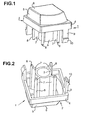
- FIG. 1 to 3 is a single key for a single key dimensionally stable plastic, e.g. Polystyrene, existing key cap 1 shown, which consists of a cover part 2 and a this plunger 3 extending underneath in the axial direction composed.
- the cover part 2 is like a keyboard push button usual, from a square key cover 4, on top of which is an approximately truncated pyramid-shaped button head 5 is placed, the top surface 6 shaped as a recessed grip is.
- Key cover 4 On the opposite side of the key 5 Key cover 4 is that of the key cover 4 perpendicular to cylindrical plunger 3 protruding below firmly attached.
- FIG. 2 shows the plunger 3 as a straight hollow cylinder circular cross section.
- stiffening ribs 7 with their Sliding cylinders 8 are arranged on the plunger 3 so that two imaginary each by two diametrically opposite Stiffening ribs 7 levels also through the corner edges the square key cover 4.
- Tongues 9 At the edge of the key cover 4 are two approximately diagonally opposite one another Tongues 9 attached, each at their free End have a snap hook 10 projecting outwards.
- the tongues 9 extend parallel to the pushbutton longitudinal axis and act as resilient snap arms. Across from the length of the plunger 3 are the tongues 9 with the snap hooks 10 shorter at their ends.
- the four sliding cylinders 8, each with a stiffening rib 7 are firmly connected to the plunger 3, are down trained longer than the plunger 3 itself. How out FIG. 3 shows, the depth of the stiffening ribs 7 is so dimensioned that the sliding cylinder 8 outside one from below acting against the plunger 3, designed as a silicone spring 11 Spring element come to rest.
- FIG. 4 shows, allows the geometry of the plunger 3 with its extended sliding cylinders 8 and the shortened, each with a snap hook 10 provided tongues 9 a Dip lubrication of pushbuttons in a lubricant bath 12.
- the lubricant can be liquid or surface smooth pasty fat.
- the immersion depth T corresponds to the vertical distance between the extreme end the snap hook 10 and the extreme end of the four are the same long sliding cylinder 8.
- FIG. 5 and 6 are for two differently shaped multi-buttons made of a dimensionally stable plastic, e.g. polystyrene, existing key caps 13 and 14 shown, the from a cover part 15 or 16, one of these in Axially extending plunger 17 and 18 and one Auxiliary guide 19 or 20 is composed.
- the cover part 15 is made in the embodiment of FIG. 5 from a rectangular Key cover 21 and in the embodiment of FIG. 6 from an angled key cover 22, on the top one laterally beveled key head 23 or 24 is placed, the Cover surface 25 or 26 as a recessed grip (in FIGS. 5 and 6 not visible) is formed.
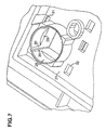
- FIG. 7 a single key is used in FIG. 7 (obliquely from below) and in FIG. 8 housing (shown obliquely from above) 27 with a shaft-like cylindrical guide opening 28, in which an upwardly delimited free space 29 for Inclusion of a silicone spring (not shown in FIG. 7 and 8) is provided.
- the shaft-like one Guide opening 28 On the inside is the shaft-like one Guide opening 28 with four axial longitudinal guides 30 provided that are diametrically opposed in pairs and whose diametrical planes form a right angle to each other.
- the longitudinal guides 30 are the sliding cylinders 8 (shown in FIGS.
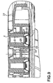
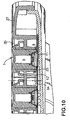
- FIG. 9 and 10 each show the button guide in a diagonal section when installing the push buttons for a keyboard.
- FIG. 9 is the starting position of the push buttons shown.
- the with their snap hooks 10 in the snap openings of the housing 27 suspended key cap 1 is with their slide cylinders 8 firmly attached to the tappet 3 in the longitudinal guides 30 of the shaft-like guide opening 28 introduced in the housing 27 from above. It gets up from below a silicone mat 33 attached and against a base plate 34 silicone spring 11 supported in the housing 27 against the plunger 3 on. Due to the cross-sectional design of the key cap guide 1, the sliding cylinder 8 outside the silicone spring 11 lie, the sliding cylinder 8 compared to Form plunger 3 extended so that a length L extended axial guidance is achieved.
- FIG. 9 is the end position of the keyboard push buttons shown.
- the key cap 1 is in its end position pressed.
- a free space 35 is available.
- the Sliding cylinder 8 of the plunger 3 of the key cap 1 meet outside the silicone spring 11 on the silicone mat 33. Due to the elongated compared to the plunger 3 Sliding cylinder 8 becomes an axial length L extended Leadership reached.
Landscapes
- Push-Button Switches (AREA)
- Eye Examination Apparatus (AREA)
- Massaging Devices (AREA)
- Perforating, Stamping-Out Or Severing By Means Other Than Cutting (AREA)
Description
Claims (15)
- Drucktaste, die im Gehäuse einer Tastatur oder einer ähnlichen Eingabeeinrichtung mittels rückfedernd ausgebildeter Schnapphaken (10) unverlierbar gehalten ist und die mit einer Tastenkappe (1) und einem darunter in Axialrichtung angeordneten Stößel (17) versehen ist, der zusammen mit mehreren an seiner Außenseite fest angebrachten axialen Führungseinrichtungen in einer im Gehäuse vorgesehenen schachtartigen Führungsöffnung (28) axial verschiebbar ist, die an ihrer Innenseite den Führungseinrichtungen des Stößels (17) formmäßig angepaßte Längsführungen aufweist und in der unten ein gegen den Stößel (17) wirkendes Federelement (11) angeordnet ist, dadurch gekennzeichnet, daß die an der Außenseite des Stößels (3) angebrachten Führungseinrichtungen jeweils über eine Versteifungsrippe (7) mit dem Stößel verbunden sind.
- Drucktaste nach Anspruch 1, dadurch gekennzeichnet, daß die an der Außenseite des Stößels (3) angebrachten Führungseinrichtungen Gleitzylinder (8) sind.
- Drucktaste nach Anspruch 2, dadurch gekennzeichnet, daß die Gleitzylinder (8) nach unten hin länger als der Stößel ausgebildet sind.
- Drucktaste nach Anspruch 2 oder 3, dadurch gekennzeichnet, daß die Bemessung der Versteifungsrippen in der Drucktasten-Querschnittebene so bemessen ist, daß die Gleitzylinder außerhalb des von unten gegen den Stößel wirkenden Federelements (11) zu liegen kommen.
- Drucktaste nach einem der Ansprüche 2-4, dadurch gekennzeichnet , daß die nach außen abstehend ausgebildeten Schnapphaken (10) an den freien Enden von mit dem Rand der Tastenkappe (1) fest verbundenen, sich zur Drucktastenlängsachse parallel erstreckenden Zungen (9) angeordnet sind und in im Gehäuse (27) passend vorgesehene Einschnappöffnungen (31, 32) mit Hinterschnitt eingreifen.
- Drucktaste nach einem der Ansprüche 2 bis 5, dadurch gekennzeichnet, daß sich die an der Innenseite der schachtartigen Führungsöffnung (28) zur Führung der Gleitzylinder des Stößels vorgesehenen und diesen formmäßig angepaßten Längsführungen (30) über die gesamte Höhe der schachtartigen Führungsöffnung erstrecken, also auch die Höhe des Federelements einschließen.
- Drucktaste nach Anspruch 5 oder 6, dadurch gekennzeichnet, daß die Zungen (9) einschließlich der an ihren freien Enden vorgesehenen Schnapphaken (10) in Axialrichtung gegenüber der Länge des Stößels (3) verkürzt ausgebildet sind.
- Drucktaste nach einem der Ansprüche 1-7, dadurch gekennzeichnet , daß pro Stößel zumindest drei vorteilhafterweise vier Führungseinrichtungen vorgesehen sind.
- Drucktaste nach Anspruch 2, dadurch gekennzeichnet, daß die jeweils über eine Versteifungsrippe (7) mit dem Stößel (3) fest verbundenen Gleitzylinder (8) in der radialen Querschnittebene des Stößels gleichmäßige Winkelabstände zueinander aufweisen.
- Drucktaste nach einem der Ansprüche 1 bis 9, dadurch gekennzeichnet, daß die schachtartige Führungsöffnung (28) vier axiale Längsführungen (30) aufweist, die sich paarweise diametral gegenüberstehen und deren diametrale Ebenen zueinander einen rechten Winkel einschließen, und daß in dazu passend zugeordneter Weise vier jeweils über eine Versteifungsrippe (7) mit dem Stößel (3) verbundene Gleitzylinder (8) vorgesehen sind, die zueinander in einer radialen Querschnittebene des Stößels einen Winkelabstand von 90° aufweisen.
- Drucktaste nach einem der vorhergehenden Ansprüche, dadurch gekennzeichnet, daß mit dem Rand der Tastenkappe (1) zwei sich im wesentlichen diagonal gegenüberliegende, jeweils einen Schnapphaken (10) an ihrem freien Ende tragende Zungen (9) fest verbunden sind und daß in dazu passender Weise mit Abstand zur schachtartigen Führungsöffnung (28) zwei Einschnappöffnungen (31, 32) mit Hinterschnitt zur Aufnahme der Schnapphaken vorgesehen sind.
- Drucktaste nach einem der Ansprüche 1 bis 11, gekennzeichnet durch eine Tauchschmierung in einem Flüssigfettbad (12) oder in einem an der Oberfläche glattgestrichenem pastösen Fett.
- Drucktaste nach einem der vorhergehenden Ansprüche, dadurch gekennzeichnet, daß sowohl für die Führung im Tastengehäuse (27) als auch für die einteilige Tastenkappe (1) ein einheitlicher Kunststoff ohne besondere Gleiteigenschaften eingesetzt wird.
- Drucktaste nach einem der vorhergehenden Ansprüche, dadurch gekennzeichnet, daß das Federelement (11) eine ringartige Silikonfeder ist, die in der schachtartigen Führungsöffnung (28) des Gehäuses (27) mit ihrem oben befindlichen Rand gegen den Stößel (3) ansteht und gegen diesen wirkend gerichtet ist.
- Drucktaste nach einem der Ansprüche 2 bis 14, gekennzeichnet durch eine Ausbildung als ohne Parallelführungsbügel versehene Mehrfachtaste, an deren Tastenkappe (13; 14) unten zusätzlich außer dem im wesentlichen zentral angeordneten, die Gleitzylinder aufweisenden Stößel (17; 18) parallel daneben noch eine oder mehrere Hilfsführungen (19; 20) fest angeordnet sind, die in Axialrichtung kürzer als der Stößel ausgebildet sind und im wesentlichen die gleiche Querschnittsform wie der Stößel mit seinen über die Versteifungsrippen verbundenen Gleitzylindern aufweisen und die in im Gehäuse zugeordnet angeordneten Führungsöffnungen geführt sind, welche die gleiche Gestaltung wie die schachtartige Führungsöffnung für die mit den Gleitzylindern versehenen Stößel haben.
Applications Claiming Priority (3)
| Application Number | Priority Date | Filing Date | Title |
|---|---|---|---|
| DE19940386A DE19940386C2 (de) | 1999-08-25 | 1999-08-25 | Drucktaste |
| DE19940386 | 1999-08-25 | ||
| PCT/DE2000/002450 WO2001015188A1 (de) | 1999-08-25 | 2000-07-26 | Drucktaste |
Publications (2)
| Publication Number | Publication Date |
|---|---|
| EP1206786A1 EP1206786A1 (de) | 2002-05-22 |
| EP1206786B1 true EP1206786B1 (de) | 2003-10-01 |
Family
ID=7919612
Family Applications (1)
| Application Number | Title | Priority Date | Filing Date |
|---|---|---|---|
| EP00956097A Expired - Lifetime EP1206786B1 (de) | 1999-08-25 | 2000-07-26 | Drucktaste |
Country Status (6)
| Country | Link |
|---|---|
| EP (1) | EP1206786B1 (de) |
| CN (1) | CN1169174C (de) |
| AT (1) | ATE251333T1 (de) |
| DE (2) | DE19940386C2 (de) |
| TW (1) | TW466518B (de) |
| WO (1) | WO2001015188A1 (de) |
Families Citing this family (8)
| Publication number | Priority date | Publication date | Assignee | Title |
|---|---|---|---|---|
| JP2003178642A (ja) | 2001-12-11 | 2003-06-27 | Polymatech Co Ltd | キーパッド及びその架橋硬化性樹脂層の分離方法 |
| DE102006012649B4 (de) * | 2006-03-20 | 2008-10-16 | Cherry Gmbh | Drucktaste mit verbesserter Tastenknopfführung |
| JP4850808B2 (ja) * | 2007-10-24 | 2012-01-11 | 日本開閉器工業株式会社 | 表示装置付き押ボタンスイッチ |
| TWI399775B (zh) * | 2008-10-31 | 2013-06-21 | Hon Hai Prec Ind Co Ltd | 推鍵裝置 |
| DE102013223843A1 (de) * | 2013-11-21 | 2015-06-03 | Zf Friedrichshafen Ag | Tastenknopf, Tastenschalter, Tastenrahmen und Leiterplatte für eine Dateneingabevorrichtung, Dateneingabevorrichtung und Verfahren zur Reduzierung eines Schaltweges eines Tastenschalters einer Dateneingabevorrichtung |
| US10809809B2 (en) | 2016-06-14 | 2020-10-20 | Hewlett-Packard Development Company, L.P. | Recessed keycaps |
| DE102017106406A1 (de) * | 2017-03-24 | 2018-09-27 | Cherry Gmbh | Tastenmodul |
| CN113451065A (zh) * | 2020-03-27 | 2021-09-28 | 致伸科技股份有限公司 | 按键结构 |
Family Cites Families (4)
| Publication number | Priority date | Publication date | Assignee | Title |
|---|---|---|---|---|
| JPS59186214A (ja) * | 1983-04-08 | 1984-10-23 | 富士通株式会社 | 押釦スイツチ |
| JPS59195632U (ja) * | 1983-06-15 | 1984-12-26 | 日通工株式会社 | 押ボタンスイツチ |
| DE3886119D1 (de) * | 1987-07-30 | 1994-01-20 | Siemens Nixdorf Inf Syst | Einzeltaste. |
| US5283408A (en) * | 1992-08-04 | 1994-02-01 | Silitek Corporation | Structure of key switch |
-
1999
- 1999-08-25 DE DE19940386A patent/DE19940386C2/de not_active Expired - Fee Related
-
2000
- 2000-07-26 CN CNB008120625A patent/CN1169174C/zh not_active Expired - Fee Related
- 2000-07-26 WO PCT/DE2000/002450 patent/WO2001015188A1/de not_active Ceased
- 2000-07-26 EP EP00956097A patent/EP1206786B1/de not_active Expired - Lifetime
- 2000-07-26 AT AT00956097T patent/ATE251333T1/de not_active IP Right Cessation
- 2000-07-26 DE DE50003934T patent/DE50003934D1/de not_active Expired - Lifetime
- 2000-09-02 TW TW089117057A patent/TW466518B/zh not_active IP Right Cessation
Also Published As
| Publication number | Publication date |
|---|---|
| DE19940386A1 (de) | 2001-04-05 |
| TW466518B (en) | 2001-12-01 |
| EP1206786A1 (de) | 2002-05-22 |
| DE19940386C2 (de) | 2002-08-14 |
| WO2001015188A1 (de) | 2001-03-01 |
| CN1371523A (zh) | 2002-09-25 |
| ATE251333T1 (de) | 2003-10-15 |
| DE50003934D1 (de) | 2003-11-06 |
| CN1169174C (zh) | 2004-09-29 |
Similar Documents
| Publication | Publication Date | Title |
|---|---|---|
| DE3131030C2 (de) | Schalterbetätigungsvorrichtung | |
| EP1868466A1 (de) | Armlehne, insbesondere für einen bürostuhl | |
| EP0100936A2 (de) | Tastenschalter | |
| DE3424771A1 (de) | Tastenfeld | |
| DE19940386C2 (de) | Drucktaste | |
| DE2142887A1 (de) | In einer Schalttafel montierbarer Schalter | |
| DE29821995U1 (de) | Verbesserte Struktur eines Hefters | |
| EP0490023B1 (de) | Drucktasteneinrichtung | |
| EP0321649A2 (de) | Feststellvorrichtung für eine mit einem Türschliesser versehene Tür | |
| DE3120555C2 (de) | Ausziehführungsgarnitur, insbesondere für Fachbretter | |
| DE102010029642B3 (de) | Schalter mit selbstjustierender Schaltstößelführung | |
| EP1206734B1 (de) | Tastaturgehäuse für ein tastenfeld einer drucktasten-tastatur | |
| DE2920836C2 (de) | ||
| EP0678885B1 (de) | Elektrischer Tastschalter | |
| WO2007107532A1 (de) | Drucktaste mit verbesserter tastenknopfführung | |
| DE3600910A1 (de) | Vorrichtung fuer den tapetenausgleich von montierten installationsgeraeten | |
| DE10316934A1 (de) | Tastenblock zum Einsetzen in eine Bedienfläche eines Haushaltsgerätes | |
| EP0813465A1 (de) | Teleskopabdeckung | |
| DE102005026894B4 (de) | Tastenanordnung für eine längliche Taste und Verwendung einer Tastenanordnung | |
| EP4021246B1 (de) | Vorrichtung zur fixierung eines schubkastens | |
| EP0770518B1 (de) | Einstellbare Kopfstützen-Führungsvorrichtung | |
| EP2050359B1 (de) | Möbelgriff | |
| DE2550026C3 (de) | Schalter | |
| DE2913913C2 (de) | Schnappschalter | |
| EP2489795B1 (de) | Betätigungsplatte für Spülauslösung |
Legal Events
| Date | Code | Title | Description |
|---|---|---|---|
| PUAI | Public reference made under article 153(3) epc to a published international application that has entered the european phase |
Free format text: ORIGINAL CODE: 0009012 |
|
| 17P | Request for examination filed |
Effective date: 20011227 |
|
| GRAH | Despatch of communication of intention to grant a patent |
Free format text: ORIGINAL CODE: EPIDOS IGRA |
|
| GRAH | Despatch of communication of intention to grant a patent |
Free format text: ORIGINAL CODE: EPIDOS IGRA |
|
| GRAA | (expected) grant |
Free format text: ORIGINAL CODE: 0009210 |
|
| AK | Designated contracting states |
Kind code of ref document: B1 Designated state(s): AT BE CH CY DE DK ES FI FR GB GR IE IT LI LU MC NL PT SE |
|
| PG25 | Lapsed in a contracting state [announced via postgrant information from national office to epo] |
Ref country code: FI Free format text: LAPSE BECAUSE OF FAILURE TO SUBMIT A TRANSLATION OF THE DESCRIPTION OR TO PAY THE FEE WITHIN THE PRESCRIBED TIME-LIMIT Effective date: 20031001 Ref country code: NL Free format text: LAPSE BECAUSE OF FAILURE TO SUBMIT A TRANSLATION OF THE DESCRIPTION OR TO PAY THE FEE WITHIN THE PRESCRIBED TIME-LIMIT Effective date: 20031001 Ref country code: CY Free format text: LAPSE BECAUSE OF FAILURE TO SUBMIT A TRANSLATION OF THE DESCRIPTION OR TO PAY THE FEE WITHIN THE PRESCRIBED TIME-LIMIT Effective date: 20031001 Ref country code: IT Free format text: LAPSE BECAUSE OF FAILURE TO SUBMIT A TRANSLATION OF THE DESCRIPTION OR TO PAY THE FEE WITHIN THE PRE;WARNING: LAPSES OF ITALIAN PATENTS WITH EFFECTIVE DATE BEFORE 2007 MAY HAVE OCCURRED AT ANY TIME BEFORE 2007. THE CORRECT EFFECTIVE DATE MAY BE DIFFERENT FROM THE ONE RECORDED.SCRIBED TIME-LIMIT Effective date: 20031001 |
|
| REG | Reference to a national code |
Ref country code: GB Ref legal event code: FG4D Free format text: NOT ENGLISH |
|
| REG | Reference to a national code |
Ref country code: CH Ref legal event code: EP Ref country code: CH Ref legal event code: NV Representative=s name: E. BLUM & CO. PATENTANWAELTE |
|
| REG | Reference to a national code |
Ref country code: IE Ref legal event code: FG4D Free format text: GERMAN |
|
| REF | Corresponds to: |
Ref document number: 50003934 Country of ref document: DE Date of ref document: 20031106 Kind code of ref document: P |
|
| GBT | Gb: translation of ep patent filed (gb section 77(6)(a)/1977) | ||
| PG25 | Lapsed in a contracting state [announced via postgrant information from national office to epo] |
Ref country code: DK Free format text: LAPSE BECAUSE OF FAILURE TO SUBMIT A TRANSLATION OF THE DESCRIPTION OR TO PAY THE FEE WITHIN THE PRESCRIBED TIME-LIMIT Effective date: 20040101 Ref country code: GR Free format text: LAPSE BECAUSE OF FAILURE TO SUBMIT A TRANSLATION OF THE DESCRIPTION OR TO PAY THE FEE WITHIN THE PRESCRIBED TIME-LIMIT Effective date: 20040101 Ref country code: SE Free format text: LAPSE BECAUSE OF FAILURE TO SUBMIT A TRANSLATION OF THE DESCRIPTION OR TO PAY THE FEE WITHIN THE PRESCRIBED TIME-LIMIT Effective date: 20040101 |
|
| PG25 | Lapsed in a contracting state [announced via postgrant information from national office to epo] |
Ref country code: ES Free format text: LAPSE BECAUSE OF FAILURE TO SUBMIT A TRANSLATION OF THE DESCRIPTION OR TO PAY THE FEE WITHIN THE PRESCRIBED TIME-LIMIT Effective date: 20040112 |
|
| NLV1 | Nl: lapsed or annulled due to failure to fulfill the requirements of art. 29p and 29m of the patents act | ||
| RAP2 | Party data changed (patent owner data changed or rights of a patent transferred) |
Owner name: FUJITSU SIEMENS COMPUTERS GMBH |
|
| ET | Fr: translation filed | ||
| PG25 | Lapsed in a contracting state [announced via postgrant information from national office to epo] |
Ref country code: LU Free format text: LAPSE BECAUSE OF NON-PAYMENT OF DUE FEES Effective date: 20040726 |
|
| PG25 | Lapsed in a contracting state [announced via postgrant information from national office to epo] |
Ref country code: MC Free format text: LAPSE BECAUSE OF NON-PAYMENT OF DUE FEES Effective date: 20040731 |
|
| PLBE | No opposition filed within time limit |
Free format text: ORIGINAL CODE: 0009261 |
|
| STAA | Information on the status of an ep patent application or granted ep patent |
Free format text: STATUS: NO OPPOSITION FILED WITHIN TIME LIMIT |
|
| 26N | No opposition filed |
Effective date: 20040702 |
|
| REG | Reference to a national code |
Ref country code: CH Ref legal event code: PFA Owner name: FUJITSU SIEMENS COMPUTERS GMBH Free format text: FUJITSU SIEMENS COMPUTERS GMBH#OTTO-HAHN-RING 6#81739 MUENCHEN (DE) -TRANSFER TO- FUJITSU SIEMENS COMPUTERS GMBH#OTTO-HAHN-RING 6#81739 MUENCHEN (DE) |
|
| PG25 | Lapsed in a contracting state [announced via postgrant information from national office to epo] |
Ref country code: PT Free format text: LAPSE BECAUSE OF NON-PAYMENT OF DUE FEES Effective date: 20040301 |
|
| PGFP | Annual fee paid to national office [announced via postgrant information from national office to epo] |
Ref country code: IE Payment date: 20100726 Year of fee payment: 11 Ref country code: CH Payment date: 20100726 Year of fee payment: 11 |
|
| PGFP | Annual fee paid to national office [announced via postgrant information from national office to epo] |
Ref country code: AT Payment date: 20100702 Year of fee payment: 11 |
|
| PGFP | Annual fee paid to national office [announced via postgrant information from national office to epo] |
Ref country code: BE Payment date: 20100728 Year of fee payment: 11 |
|
| REG | Reference to a national code |
Ref country code: DE Ref legal event code: R084 Ref document number: 50003934 Country of ref document: DE |
|
| REG | Reference to a national code |
Ref country code: GB Ref legal event code: 746 Effective date: 20110527 |
|
| BERE | Be: lapsed |
Owner name: *FUJITSU SIEMENS COMPUTERS G.M.B.H. Effective date: 20110731 |
|
| REG | Reference to a national code |
Ref country code: DE Ref legal event code: R082 Ref document number: 50003934 Country of ref document: DE Representative=s name: EPPING HERMANN FISCHER, PATENTANWALTSGESELLSCH, DE Effective date: 20111229 Ref country code: DE Ref legal event code: R081 Ref document number: 50003934 Country of ref document: DE Owner name: FUJITSU TECHNOLOGY SOLUTIONS INTELLECTUAL PROP, DE Free format text: FORMER OWNER: FUJITSU SIEMENS COMPUTERS GMBH, 80807 MUENCHEN, DE Effective date: 20111229 Ref country code: DE Ref legal event code: R082 Ref document number: 50003934 Country of ref document: DE Representative=s name: EPPING HERMANN FISCHER PATENTANWALTSGESELLSCHA, DE Effective date: 20111229 |
|
| REG | Reference to a national code |
Ref country code: CH Ref legal event code: PL |
|
| REG | Reference to a national code |
Ref country code: AT Ref legal event code: MM01 Ref document number: 251333 Country of ref document: AT Kind code of ref document: T Effective date: 20110726 |
|
| REG | Reference to a national code |
Ref country code: IE Ref legal event code: MM4A |
|
| PG25 | Lapsed in a contracting state [announced via postgrant information from national office to epo] |
Ref country code: BE Free format text: LAPSE BECAUSE OF NON-PAYMENT OF DUE FEES Effective date: 20110731 Ref country code: CH Free format text: LAPSE BECAUSE OF NON-PAYMENT OF DUE FEES Effective date: 20110731 Ref country code: LI Free format text: LAPSE BECAUSE OF NON-PAYMENT OF DUE FEES Effective date: 20110731 |
|
| PG25 | Lapsed in a contracting state [announced via postgrant information from national office to epo] |
Ref country code: IE Free format text: LAPSE BECAUSE OF NON-PAYMENT OF DUE FEES Effective date: 20110726 |
|
| PG25 | Lapsed in a contracting state [announced via postgrant information from national office to epo] |
Ref country code: AT Free format text: LAPSE BECAUSE OF NON-PAYMENT OF DUE FEES Effective date: 20110726 |
|
| REG | Reference to a national code |
Ref country code: FR Ref legal event code: PLFP Year of fee payment: 17 |
|
| REG | Reference to a national code |
Ref country code: FR Ref legal event code: PLFP Year of fee payment: 18 |
|
| REG | Reference to a national code |
Ref country code: FR Ref legal event code: PLFP Year of fee payment: 19 |
|
| PGFP | Annual fee paid to national office [announced via postgrant information from national office to epo] |
Ref country code: DE Payment date: 20180727 Year of fee payment: 19 Ref country code: FR Payment date: 20180723 Year of fee payment: 19 |
|
| PGFP | Annual fee paid to national office [announced via postgrant information from national office to epo] |
Ref country code: GB Payment date: 20180725 Year of fee payment: 19 |
|
| REG | Reference to a national code |
Ref country code: DE Ref legal event code: R082 Ref document number: 50003934 Country of ref document: DE Representative=s name: EPPING HERMANN FISCHER PATENTANWALTSGESELLSCHA, DE Ref country code: DE Ref legal event code: R081 Ref document number: 50003934 Country of ref document: DE Owner name: FUJITSU CLIENT COMPUTING LIMITED, KAWASAKI-SHI, JP Free format text: FORMER OWNER: FUJITSU TECHNOLOGY SOLUTIONS INTELLECTUAL PROPERTY GMBH, 80807 MUENCHEN, DE |
|
| REG | Reference to a national code |
Ref country code: GB Ref legal event code: 732E Free format text: REGISTERED BETWEEN 20190725 AND 20190731 |
|
| REG | Reference to a national code |
Ref country code: GB Ref legal event code: 732E Free format text: REGISTERED BETWEEN 20190801 AND 20190807 |
|
| REG | Reference to a national code |
Ref country code: DE Ref legal event code: R119 Ref document number: 50003934 Country of ref document: DE |
|
| GBPC | Gb: european patent ceased through non-payment of renewal fee |
Effective date: 20190726 |
|
| PG25 | Lapsed in a contracting state [announced via postgrant information from national office to epo] |
Ref country code: DE Free format text: LAPSE BECAUSE OF NON-PAYMENT OF DUE FEES Effective date: 20200201 Ref country code: GB Free format text: LAPSE BECAUSE OF NON-PAYMENT OF DUE FEES Effective date: 20190726 |
|
| PG25 | Lapsed in a contracting state [announced via postgrant information from national office to epo] |
Ref country code: FR Free format text: LAPSE BECAUSE OF NON-PAYMENT OF DUE FEES Effective date: 20190731 |